
Manufacturer's Specifications
FM Tuner Section
Usable Sensitivity: Mono, 10.3 dBf; stereo, 19.17 dBf.
50-dB Quieting Sensitivity: Mono, 16.07 dBf; stereo, 40 dBf.
Signal-Seeker Sensitivity: 25.19 dBf.
S/N: Mono, 85 dB; stereo, 80 dB.
THD at 50-dB Quieting: Mono, 0.3%; stereo, 0.4%.
THD at 65 dBf in Wide Mode: Mono, 0.05% at 100 Hz and 1 kHz, 0.1% at 6 kHz; stereo, 0.1% at 100 Hz, 1 kHz, and 6 kHz.
Frequency Response: 20 Hz to 15 kHz, ± 0.5 dB.
Stereo Separation: Wide mode, 50 dB at 100 Hz and 1 kHz, 45 dB at 10 kHz.
Capture Ratio: Wide mode, 1.3 dB; narrow mode, 3.0 dB.
Selectivity: Wide mode, 40 dB; narrow mode, 80 dB.
Image Rejection: 120 dB.
I.f. Rejection: 120 dB.
AM Suppression: 60 dB.
Subcarrier Rejection: 80 dB at 19 kHz, 90 dB at 38 kHz.
Stereo Threshold: 19.17 dBf.
AM Tuner Section:
Usable Sensitivity: With supplied loop antenna, 400 µV/m; with external antenna, 200 µV.
Signal-Seeker Sensitivity: 500µV/m.
S/N Ratio: 55 dB.
Image Rejection: 40 dB.
I.f. Rejection: 65 dB.
Selectivity: 50 dB, ±10 kHz.
THD: 0.3%.
Frequency Response: 2.5 kHz, +0,-3 dB.
Amplifier Section
Power Output: 150 watts/channel into 8 or 4 ohms, from 20 Hz to 20 kHz.
Rated THD: 0.007% into 8 ohms, 0.015% into 4 ohms.
SMPTE IM: 0.007% into 8 ohms, 0.015% into 4 ohms.
Damping Factor: 50.
Dynamic Headroom: 2.0 dB.
Slew Factor: 3.
Frequency Response: Phono (RIAA), 20 Hz to 20 kHz, ± 1.0 dB; high level, 20 Hz to 20 kHz, ± 0.5
dB Input Sensitivity, re: 1 Watt Output: MM phono, 0.204 mV; MC phono, 20.4 µV; high level, 12 mV.
S/N: MM phono, 82 dB; MC phono, 70 dB; high level, 100 dB.
Phono Overload: MM phono, 160 mV; MC phono, 16 mV.
Bass and Treble Control Range: ±10 dB.
Subsonic Filter: -3 dB at 15 Hz, 12 dB/octave.
Loudness Contour: +8 dB at 100 Hz and +4 dB at 10 kHz, for volume-control setting of -30 dB.
D/A Converter Section:
Sampling Frequencies: 32 kHz, 44.1 kHz, and 48 kHz.
D/A Conversion: Full 18-bit linear, dual D/A converters.
Coaxial Input Level: 500 mV peak to peak.
Filters: Digital filter, eight-times over-sampling; analog low-pass filter, third-order linear-phase.
Frequency Response: 20 Hz to 20 kHz, ±0.3 dB.
S/N: 115 dB. Dynamic Range: 97 dB. THD at 1 kHz: 0.004%.
Channel Separation: 90 dB.
General Specifications:
Power Requirements: 120 V a.c., 50/60 Hz, 400 watts.
Dimensions: 18 7/8 in. W x 6 in. H x 17 in. D (48 cm x 15.2 cm x 43.2 cm).
Weight: 46.2 lbs. (21 kg).
Price: $1,200.
Company Address: 21350 Lassen St., Chatsworth, Cal. 91311.
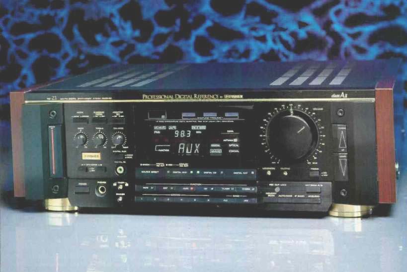
Just by examining its comprehensive list of specifications, you have to conclude that the Model RS-Z1 is not the run-of-the-mill, "me-too" kind of component you get from some giant Japanese companies which, in their own domestic market, don't sell receivers at all. I must confess that when the editors of Audio asked me to test and review a Fisher receiver, I had mixed feelings about the project. For one thing, I am an alumnus of the "original" Fisher Radio Corporation's Engineering Department, having worked there for a half-dozen years when its founder, Avery Fisher, was in charge. As many loyal readers know, Mr. Fisher sold the company in the late 1960s to the Emerson Electric Co. of St. Louis, which, after a short time, sold it to Sanyo Corp. While many Sanyo products certainly rank high in quality and sophistication, the early years of the Sanyo-Fisher relationship saw a shift in emphasis from high-end, state-of-the-art audio components to everything from rack systems (at every price level) to video components. Nothing wrong with that, of course, except that it didn't really preserve the original Fisher image in the minds of old-time audiophiles (including me). Well, it is now obvious that when they want to, Sanyo can design and make products under the Fisher name and trademark that are truly top-grade. The Fisher RS-Z1, introduced recently as part of what the company calls its Professional Digital Reference series, is a well-designed receiver that not only delivers high power levels with low distortion but is equipped with an excellent AM/FM tuner section and is designed to accommodate digital input signals at any of the three standard sampling frequencies that are currently in use worldwide.
The RS-Z1 AM/FM stereo receiver is the "flagship" of Fisher's Professional Digital Reference Series, which consists of seven audio and video products. The receiver incorporates Class A-2 amplifier circuitry that combines the low distortion of Class-A amplifier design with the higher efficiency of a Class-AB configuration. The power rating is 150 watts per channel into 8 ohms, from 20 Hz to 20 kHz, with no more than 0.007% THD. My sample didn't quite meet every single amplifier distortion spec and tuner spec in its owner's manual (it came very close to those that it missed), but I have absolutely no quarrel with the measured performance of this receiver. Furthermore, Fisher is to be commended for listing just about every performance specification that is currently required for conformance with the IHF/IEEE FM Tuner Measurement Standard and with the EIA Amplifier Measurement Standard. That's more than I can say about some of the other "major" manufacturers who, for reasons known only to themselves, omit certain fairly important specifications from their manuals and brochures more often than not.
The most notable aspect of the RS-Z1 is that it has digital inputs and outputs for use with CD players, DAT recorders, and (possibly) digital satellite broadcast receivers in the future. Only two of those digital connections are the coaxial electronic type; the others are all optical fiber. Optical interfacing is said to reduce or eliminate the possibility of r.f. interference and other forms of signal degradation. In its digital circuitry, the RS-Z1 employs two linear, 18-bit D/A converters plus eight-times oversampling. The receiver is supplied with a Model RRS-Z1 remote control.

Control Layout
The front panel of the RS-Z1 is three-dimensional in appearance, owing to the sloped metal pieces at either end. A large vertical "Stand By" switch on the left end-piece operates in conjunction with the main power switch below, on a sloping section of the main panel. On the right end-piece are the buttons for tuning up and down, which operate either in the station-seeking or the manual tuning mode.
The slightly sloped lower section of the panel contributes further to the three-dimensional look and also makes for better visibility of controls found on its surface. Besides the power switch, these include a 'phone jack, a timer switch (for 30or 60-minute turn-off), a display dimmer switch, analog input selector buttons, six numbered station preset buttons, and FM and AM band-selector buttons. There are six memories per band, but because the "FM" button cycles through three FM "bands," a total of 18 FM stations can be memorized, as opposed to six AM stations. Further to the right, still on the sloped lower portion of the panel, are an "Antenna A/B" selector, a "Memory Scan" button, an auto/ manual tuning button, an i.f. bandwidth selector (wide or narrow), and a high-blend selector for reduced separation and noise when listening to weak stereo FM signals. A "Rec Out Lock" button locks the tape outputs to the currently selected source, so you can continue recording from that source even after switching to another source for listening.
This is a rather unusual way of selecting the record out, but it works just as well as having two selector switches and takes up a lot less front-panel space.
The main, central portion of the front panel has a massive, accurately calibrated master volume control at the extreme right. With power applied, an indicator light above the volume control illuminates. Below the rotary volume control are a phono MM/MC selector button, an audio muting button, and a loudness switch. The left end of this main control area houses rotary bass, treble, and balance controls, separate A and B speaker-selector buttons, a mono/stereo switch, a subsonic filter switch, and an "Adaptor EQ" switch, which controls the jacks on the rear panel for the external processor loop. An unusual feature is the coaxial digital input on the front panel, with a switch selecting between it and the rear-panel "Digital AUX" jacks.
A large display area at the center of the front panel shows both the signal source and the frequency of the currently tuned station in large characters. Smaller indicators on the display show whether the source is analog or digital (and whether a digital source is coaxial or optical), the sampling frequency of the digital input signal, and whether high blend, loudness, muting, and wide i.f. settings are in use. Other tuner information displayed includes the current band and preset number, which antenna is in use, signal strength (shown graphically), and center tuning. The display also shows if the sleep timer has been engaged and, if so, whether for 30 or 60 minutes.
Below the display are a "Source Direct" button, which bypasses the tone controls and filter, and three buttons for selecting the digital inputs. Green and red lights on the "Digital AUX" and "Digital CD" buttons show when the digital and analog record-out terminals are active. However, because the "Digital DAT" input doesn't feed the digital record-out jack, its button only has a red light.
The rear panel houses two 75-ohm coaxial antenna connectors for FM, plus a pair of AM antenna terminals to which either a supplied loop or any other external antenna can be connected. A 300-ohm/75-ohm transformer is supplied in case your FM antenna has a 300-ohm twin-lead transmission line. Phono and high-level analog inputs and a ground terminal are adjacent to the antenna terminals, while further inboard are two sets of tape record-out/monitor jacks and the "Adaptor EQ" jacks, normally interconnected by jumpers in the absence of any external signal processor. Large, color-coded speaker terminals are further to the right, and below them are three convenience a.c. outlets (two switched, one unswitched). Finally, at the extreme right, are a coaxial digital input, an optical digital input labeled for a CD player, and two more optical connectors labeled for the record-out and playback connections of a DAT recorder.
The supplied RRS-Z1 remote control not only has buttons for most of the functions of the receiver but can also be used to operate other components in Fisher's Professional Digital Reference series.
Tuner Section Measurements
Figure 1 shows frequency response of the FM tuner section, measured at the speaker terminals, with the tone controls bypassed. Response was flat to within +0.4, 1 dB from 30 Hz to 15 kHz. (The dashed curve, representing right-channel output, was displaced for the sake of clarity; output levels were the same for both channels.) The quieting characteristics of the FM tuner section are shown in Fig. 2. Fifty-dB quieting required a signal input of only 14.5 dBf in mono (as against 16.07 dBf stated by Fisher) and 37.5 dBf in stereo (against 40 dBf claimed by the manufacturer). Best signal-to-noise ratio for strong signals was 80 dB in mono and 76.5 dB in stereo. Both figures fall a bit short of the numbers claimed by Fisher but are certainly better than average for the FM tuner sections found in most receivers. Notice that below 20 dBf, the output is muted when the tuner is set to the stereo mode. This, then, constitutes the true stereo threshold, and it is almost precisely where Fisher claims it to be.

Fig. 1-Frequency response, FM tuner section. Right-channel response (dashed
curve) has been displaced downward slightly for clarity.

Fig. 2-FM quieting characteristics.

Fig. 3-THD + N vs. signal level.

Fig. 4-THD + N vs. frequency.

Fig. 5-FM frequency response and stereo separation.

Fig. 6--Spectrum analysis showing crosstalk products for a 5-kHz signal.
Figure 3 shows how distortion plus noise varied with increasing signal input. Using the wide i.f. mode, usable mono sensitivity (the amount of signal required to reduce THD + N to 3%) measured 11.8 dBf. In mono, THD + N at strong signal levels was 0.06%, while in stereo, THD + N measured 0.24% at 65 dBf. Switching to the narrow i.f. mode, THD + N increased, as you would expect. In mono, it was now about 0.1%, while in stereo it increased to 0.9% at 65 dBf. These results clearly illustrate why it is best to use the wide i.f. mode whenever no interference from adjacent or alternate-channel signals is present. (In the plots of Fig. 3, a 1-kHz modulating signal was used.) In Fig. 4, I plotted THD + N versus frequency for strong signals in mono and stereo, first using the wide i.f. mode and then the narrow mode. Of great interest was the fact that distortion varied only slightly with frequency. In fact, the THD + N figures for stereo at 6 kHz were actually lower in both i.f. modes than they were at 1 kHz.
I made three separate measurements of FM stereo separation (Fig. 5). First, I plotted separation versus frequency in the wide i.f. mode. This separation is represented by the almost horizontal dashed curve and the uppermost solid curve. Under these conditions, separation was 46.5 dB at 1 kHz, 47.5 dB at 100 Hz, and 42.6 dB at 10 kHz. Switching to the narrow i.f. mode actually resulted in a slightly higher separation figure at 1' kHz (48 dB) but lower figures at 100 Hz and 10 kHz (45.5 dB and 29 dB, respectively). Finally, reverting to the wide i.f. mode, I activated the high-blend circuit, which further reduced separation at 1 kHz to about 16.5 dB and to virtually nothing at 10 kHz. Frequency response for the modulated channel was also affected somewhat when the high-blend circuit was employed, as you can see from the lowest solid-line curve, which rolls off slightly at the treble end of the plot.
An examination of crosstalk for a 5-kHz modulating signal (Fig. 6) revealed excellent suppression of 19-kHz and 38 kHz subcarrier components; both were down more than 80 dB below 100% modulation levels in the unmodulated channel. Even some of the best tuners I have measured recently don't manage to suppress these unwanted components that far.
Capture ratio was measured only in the wide i.f. mode and was exactly 1.3 dB, as claimed. Selectivity was 42 dB in the wide mode and 80 dB in the narrow mode. Image, i.f., and spurious-response rejection were all in excess of 100 dB, the highest I can measure with my test equipment. The RS-Z1's AM suppression was 58 dB. Figure 7 shows the frequency response of the AM tuner section. The treble -6 dB point occurred just above 4 kHz (better than most AM sections I've tested, and better than the 2.5 kHz claimed by Fisher). However, the bass rolled off rather quickly below 100 Hz, and I can't imagine why Fisher designed the AM section that way. Since the company published rather complete AM specifications, I took the trouble to check a few of them before going on to the amplifier section. Maximum signal-to-noise ratio was 55 dB, as claimed. THD measured 0.35%, a bit more than the 0.3% claimed by Fisher. Selectivity measured 45 dB. I suspect that the sensitivity figures given by Fisher contain a misprint.
The specification for external AM antenna sensitivity was probably meant to read 20 µV rather than 200 µV, since I measured it at about 22 µV.

Fig. 7-AM frequency response.

Fig. 8-Amplifier section frequency response, using high-level analog input.

Fig. 9-Amplifier section THD + N vs. frequency at rated output of 150 watts
per channel into 8 ohms.

Fig. 10-THD + N vs. power output per channel into loads of 8 ohms (A) and
4 ohms (B), at frequencies of 20 Hz, 1 kHz, and 20 kHz. Note the unusual
similarity of the three curves in each case.

Fig. 11-SMPTE-IM distortion vs. power output.

Fig. 12-Bass and treble control range.
Amplifier Section Measurements
Measured via one of the high-level analog inputs, overall frequency response for the amplifier section of the RS-Z1 was flat to within-0.5 dB from 20 Hz to 20 kHz, as shown in Fig. 8. The-3 dB point for the treble end of the spectrum occurred above 60 kHz. Fisher rates the power output of this amplifier as 150 watts per channel into both 8-ohm and 4-ohm load impedances. In Fig. 9, I plotted THD + N versus frequency while maintaining output of a constant, regulated 150 watts per channel. From 20 Hz to 3 kHz, THD + N was well below 0.01% (0.0045% at 1 kHz). At higher frequencies, THD rose a bit, reaching the altogether acceptable figure of 0.025% at 20 kHz. Although this doesn't quite correspond to the claimed 0.007%, it certainly didn't upset me. Fisher may want to rethink their published specs, however, if this excellent result is typical, since the FTC requires that the rated THD be met at all audio frequencies listed in the power rating.
Figures 10A and 10B are plots of THD + N versus power output for 8-ohm and 4-ohm loads. For 8-ohm loads, clipping did not occur until output levels in both channels reached more than 167 watts per channel. The curves for 1 kHz, 20 Hz, and 20 kHz were almost identical at all levels except near clipping, when the THD + N for a 20-kHz signal rose a bit before final overload. In the case of 4-ohm loads (Fig. 10B), results were also excellent; all three test frequencies resulted in similar plots, and clipping did not occur until about 263 watts per channel were being delivered to the 4-ohm loads! Figure 11 is a plot of SMPTE-IM distortion versus equivalent power output level. Plots were made for both 8-ohm and 4-ohm loads.
Damping factor for the amplifier section, referred to 8 ohms and with a test signal of 50 Hz, measured 70, which is considerably more than the 50 claimed by Fisher. Dynamic headroom was an impressive 2.12 dB, a bit higher than claimed. Signal-to-noise ratio, referred to 1-watt output and with 500 mV of input, measured 78.5 dB for the high-level inputs. I suspect that Fisher's published S/N figure of 100 dB, though referred to as an IHF measurement, is in fact referred to rated output rather than to 1 watt, as prescribed by the measurement standard. If I were to translate the 78.5 dB figure to rated output, I would have to add 21.8 dB to my reading, for a total S/N figure of 100.3 dB. Input sensitivity for the high-level analog inputs was 16.5 mV for 1-watt output.
Range of cut and boost for the bass and treble tone controls is shown in Fig. 12. Maximum boost and cut were almost precisely 10 dB at 100 Hz and at 10 kHz. I did feel that the tone control action extended a bit too far into the midrange region. The action of the loudness contour circuitry is shown in the graph of Fig. 13, for volume control levels from 0 dB (maximum setting) to-40 dB. Next, I measured the performance of the phono section.
The RIAA equalization was quite accurate, deviating from the prescribed playback curve by about +0.7 dB at 30 Hz and-1.0 dB at 20 kHz, as shown in Fig. 14. Phono input sensitivity for 1-watt output measured 0.2 mV for the MM inputs and 20 µV for the MC inputs. Signal-to-noise ratio for the MM inputs, using an input signal of 5 mV and reducing the volume control setting to produce 1-watt output, measured 78 dB; for the MC inputs (using a 500-0 signal and the same 1-watt output), the S/N was 68 dB.

Fig. 13-Loudness characteristics for volume-control settings from 0 (full
up) to-40 dB.

Fig. 14-RIAA equalization error.
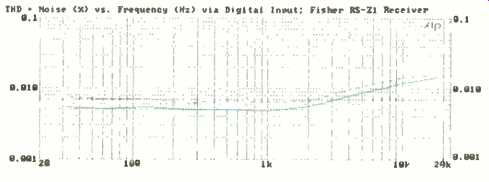
Fig. 15-THD + N vs. frequency, using digital input, at 135 watts output.
Note the similarity to Fig. 9; see text.
The Digital-Input Afterthought
Since Fisher went to all that trouble to provide this receiver with optical and digital inputs, I felt I had to check them out as well, even though most users are not likely to connect very many components to the digital inputs (coaxial or optical) of this receiver just yet. Be prepared for the future--that's my motto! For the few remaining tests I wanted to make, I decided to set the "reference output level" at around 135 watts into 8 ohm loads. I connected the coaxial digital output of one of my reference CD players to the "Digital AUX" circuit's front panel input jack (an unusual convenience that I now fully appreciated). Then, using my CD-1 standard test disc, I performed some of the tests that I usually make when evaluating a CD player-only this time, the entire D/A conversion system and analog amplification circuitry of the Fisher RS-Z1 were included in the measurement loop. It should be understood, therefore, that the THD, linearity, and noise readings that I obtained are not strictly confined to the D/A circuitry of the RS-Z1. When you stop to think of it, that's entirely fair, since this is the way a user would have to listen to the equipment even if he uses the digital inputs--at least until someone comes up with an all-digital signal chain, right up to the loudspeakers. That having been said, examine Fig. 15, which is a plot of THD + N versus frequency. Of course, it is quite similar to Fig. 9, except that THD levels are somewhat lower (especially at the treble end of the plot) simply because the power output level of 135 watts that I was using for reference was a bit below the receiver's rated output.
Referred to that same output level, A-weighted S/N measured 99.6 dB rather than the 115 dB claimed by Fisher.
Obviously, since I had already established that the amplifier’s high-level S/N ratio was around 100 dB, that had to be the limiting factor in this measurement (even though the D/A circuitry of the receiver may well be delivering its claimed S/N ratio of 115 dB). The spectrum analysis of the noise, plotted from 30 Hz to 20 kHz (Fig. 16), shows that the major contributors to the overall S/N of the system in this test were the power-line component of 60 Hz and its third harmonic, 180 Hz.
My big surprise came when I checked linearity through the entire system (my CD player's digital output signals, fed to the digital input of the receiver, translated back to analog by the receiver's D/A circuitry, and amplified to a 135-watt level by the RS-Z1 amplifier section). For the results shown in Fig. 17, I used undithered test signals at levels from 0 to-90 dB. Linearity was as close to perfect as I've seen from any CD player, and substantially better than what I know my two-year-old reference CD player could have done had I extracted the signal from its analog outputs! Here, then, was a good justification for bypassing the D/A circuitry in all but the most linear of CD players. The same thing occurred to me when I plotted the deviation from linearity for low-level dithered signals (Fig. 18). Now, deviation at-100 dB was less than 2 dB for the right channel and less than 4 dB for the left channel.
Finally, using the EIAJ method for measuring dynamic range of the total system, I came up with a reading of 99.1 dB for the left channel and 101.0 dB for the right channel.
One could hardly ask for more than that from any complete combination, let alone a CD player connected to an all-in-one receiver.

Fig. 16--Spectrum analysis of residual noise when playing "no signal" track
of CD-1 test disc through digital input. The solid curve is for the left
channel and the dashed curve is for the right.

Fig. 17--Deviation from perfect linearity using undithered signals; see text.
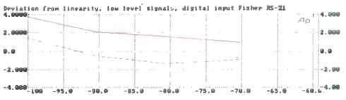
Fig. 18--Deviation from linearity using dithered, low-level signals.
Use and Listening Tests
The Fisher RS-Z1 receiver is easy to hook up and easy to use. All controls and their functions are thoroughly described in the 23-page owner's manual. An excellent and complete hookup diagram shows you how and where to connect components, using either the analog or digital inputs or combinations of both.
The FM tuner section was quite sensitive, and being able to select wide or narrow i.f. mode increased the number of usable signals in my location to 56. Had I needed to remain in the wide mode all the time, some half dozen of these signals would have encountered intolerable amounts of adjacent-channel interference.
My first listening tests involving CDs and DAT recordings were all done with the analog outputs of those devices connected to the analog inputs of the receiver, and results were more than satisfactory. What little hum and noise there was could only be detected audibly when I turned up the volume control enough to yield ear-shattering listening levels during louder passages. As for the sound quality, it was, of course, a function of the analog amplification stages, but I was pleased with what I heard-especially the tight bass, which made the Fisher seem more powerful than its rating of 150 watts per channel would suggest, even on my low efficiency reference speakers. The dynamic headroom helps here, no doubt, along with the ability of the receiver to deliver low-frequency signals at high power levels with no more distortion than it delivers at mid-frequencies.
When it came time to pack up the receiver and return it to the manufacturer, I couldn't help thinking that even the exacting Avery Fisher would be proud of this latest product to bear his name.
-Leonard Feldman
(Audio magazine, Aug. 1990)
Also see:
Fisher 801 Four Channel AM/FM Stereophonic Receiver (Jul. 1972)
Fisher ST-425 Speaker System (Jan. 1975)
Fisher MT-6250 Linear Motion Semi-Automatic Turntable (Jun. 1980)
JVC R-X80 Receiver (Nov. 1983)
= = = =