by Dick Crawford
A ROOM EQUALIZER is to a loudspeaker what makeup is to a woman: it can change the character, the mood, the color. I'm going to discuss some of the characteristics of good room equalizers, and then show a circuit that can be used as a room equalizer, or, if you prefer, as an electronic crossover network, or both.
What exactly is a room equalizer? To my mind it is a sophisticated tone control. I say sophisticated because a room equalizer has many separate frequency bands rather than just bass and treble. This gives it the ability to correct for loudspeaker or room characteristics more exactly. For example, if a room is unusually resonant at a certain frequency, then the resonance can be corrected by the equalizer without seriously affecting other frequencies.
A room equalizer has filters that separate the audio signal into frequency bands, and then attenuators which set the gain in each of these bands. Next the output of each band is combined with all the other bands to reconstitute the audio signal, now equalized. One obvious way to make an electronic crossover would be to combine only the lower frequency bands to create the woofer channel; another group of bands would form the midrange, and the final set of bands would go to the tweeter. Such an arrangement would give the advantages of a room equalizer and an electronic crossover network. More of this later, let's now turn to the criteria of a good room equalizer.
1. Flat frequency response. If the equalizer is set "flat," that is, no equalization, then its frequency response should be just that. This is difficult to achieve in most room equalizer designs because it requires excellent matching of the reactive components in the filter for each band. The normal 10% tolerance on electronic parts is too much for such matching.
2. Sharp cutoff at band edges. The filter should cutoff at 12 decibels per octave or more so that adjusting one band won't significantly affect adjacent bands.
3. Sufficient bands. Obviously the more bands, the greater the flexibility, but too many bands and adjustment becomes difficult. Keep in mind that we are correcting for characteristics that we hope are relatively broadband. I chose octave bandwidths as being a reasonable compromise between complexity and versatility.
4. Calibration. It seems desirable to me that the gain adjustment for each band should be calibrated so that the user knows what equalization he is using.
5. Distortion. The room equalizer should not add appreciable distortion to the signal at any setting of the controls. This applies to hum and noise also.
How do we design a room equalizer to meet these goals? I used a. clever technique suggested to me by Bernard M. Oliver and shown in Fig. 1. Start with a suitable low-pass filter. Then you subtract the output of the low-pass filter from the original input signal. The subtracted signal behaves as if it had gone through a high-pass filter. Simple. But you have to be careful in the design of the low-pass filter in order to get a symmetrical response, that is, one in which both the low-pass and the high-pass attenuations are of similar slope in decibels per octave. Dr. Oliver also figured this out, and Fig. 2 shows some of the theoretically possible characteristics for different transfer functions.
One characteristic of this class of filter (at least as so far developed) is the peaking in the vicinity of crossover. Indeed, these peaks are necessary when dealing with filters of greater than nine decibels per octave slope. This is because of the phase shift in each filter, leading to signals that partially oppose at crossover. Without the peaks there would be a dip in the response at crossover. This is one reason why careful crossover design is necessary with conventional crossover networks to avoid interference dips in the response.
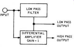
Fig. 1-Supplementary filter.
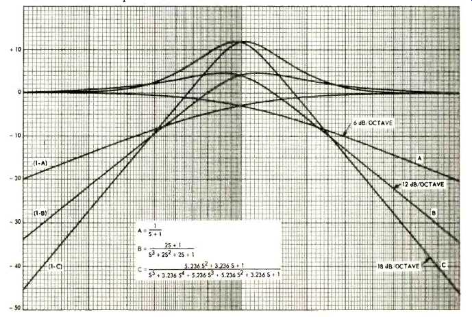
Fig. 2--Responses of supplementary filters
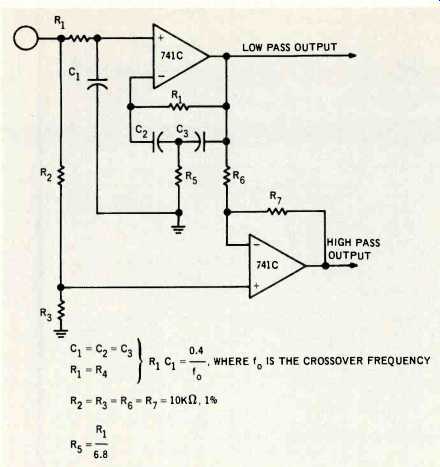
Fig. 3--Circuit diagram of supplementary filter.
As the reader can see from Fig. 2, the difficulty with the higher order filters is that the peak response near crossover grows inordinately. I chose the 12 decibel per octave case. It is possible to synthesize the transfer functions shown in Fig. 2 exactly, and the results are very close to those predicted.
A cheaper and simpler method is to approximate the desired low pass with the circuit of Fig. 3.
Incidentally, there may be some confusion as to where the crossover frequency is located. If we adopt the conventional-3 decibel point, then we have different crossover frequencies for the low and high pass sections of the same filter! I hope the reader won't object if I define the crossover frequency as that point where the response of the high pass section crosses over the response of the low pass section even though the response of both of these is greater there than it is in the midband of either section.
Figure 4 shows how the basic circuit of Fig. 3 is repeated and connected to form a nine-band equalizer. The circuit is shown only for a single channel, but for stereo can be simply repeated. Notice that the bandpass sections are created by taking the difference between two low-pass sections. Likewise the high frequency cutoff of band 8 (4-8 kHz) also creates the low frequency of band 9 (8 kHz). There is no high frequency cutoff for band 9, other than what is the natural limit of the amplifiers used, so band 9 is asymmetrical. If the reader wants a rapid cutoff at 20 kHz and 20 kHz, then he can substitute the circuit of Fig. 5 for the portion of Fig. 4 within the dotted lines. The 20 kHz cutoff allows boosting the bass without suffering from infrasonic interference such as turn table rumble. The 741C operational amplifiers can be Texas Instruments SN72741P, Fairchild U9T7741393, RCA CA3741CT or any other 741C you may happen to like. There are 30 of these operational amplifiers used in this design and at this quantity the price varies from $1.04 to $1.50 depending on the source. I did not show all the power supply wiring in order to simplify Fig. 4, but, as you might imagine, the plus 15 volts is connected to pin 7 and the minus 15 volts to pin 4 of all the 741C's.
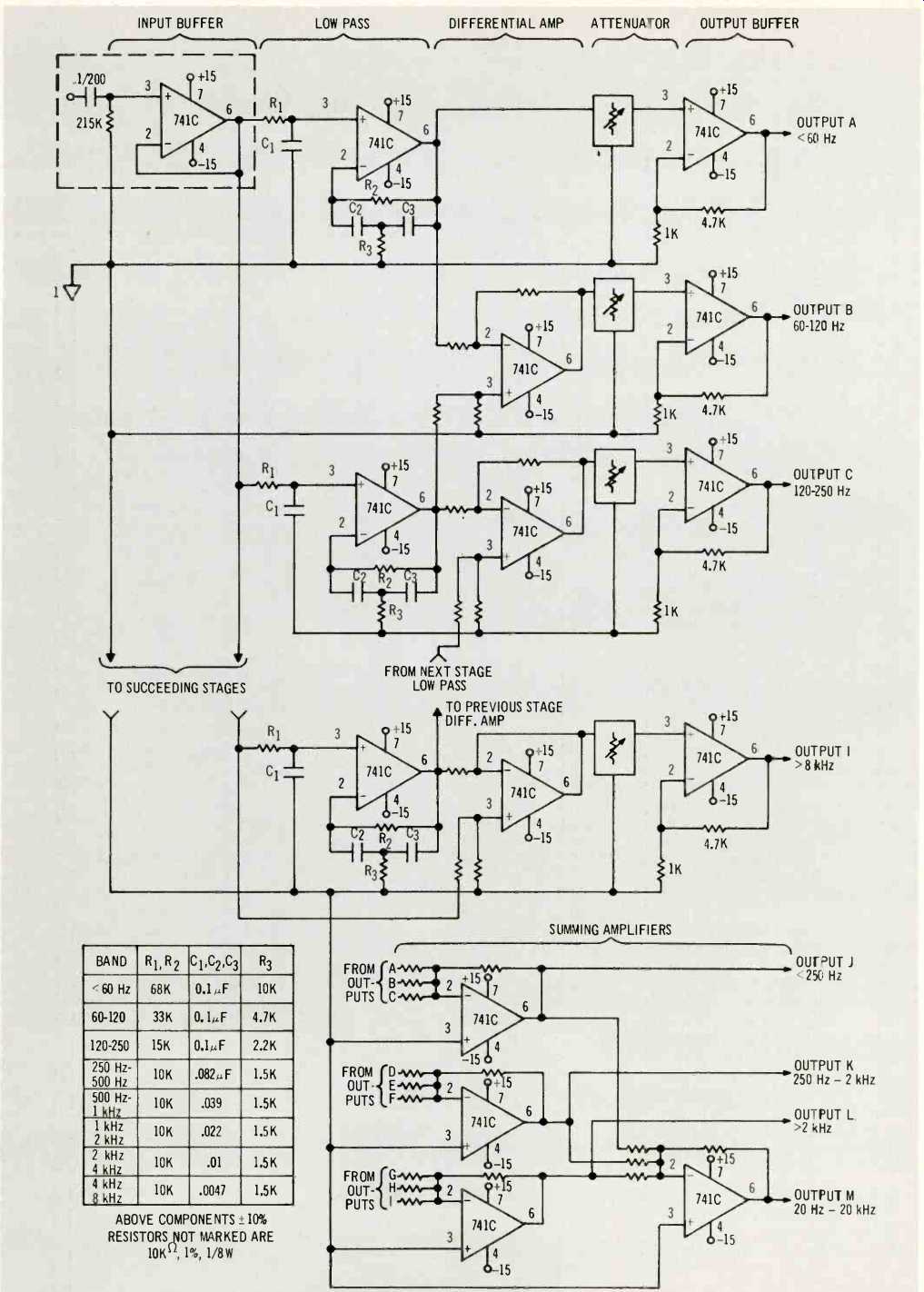
Fig. 4-Circuit diagram of room equalizer.
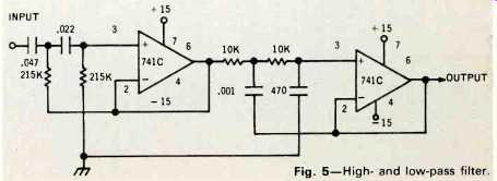
Fig. 5-Highand low-pass filter.
The output of each band is brought to a front panel connector in the unit I built, as this might be useful for some forms of experimentation or analysis.
Notice that each band of the room equalizer has its own attenuator. The schematic of the attenuator is shown in Fig. 6 along with the power supply.
The values shown for the attenuator resistors result in 3 decibel steps, for a possible boost of 15 decibels or a cut of 18 decibels in each band. If you use 1% resistors the attenuator will be within about 0.25 decibels accuracy. 5% resistors will give at worst about 1 decibel accuracy, and 10% resistors about 2 decibels.
The power supply, shown in Fig. 6, is a simple design which can easily supply the 60 milliamperes required for a single channel. Note that for stereo, heat sinks (fan top radiators or the like) should be placed on the two transistors in the power supply.
Returning to Fig. 4, we see that the values for the components used in the low-pass filter sections are shown in a table. One advantage of this design is the convenient and non-critical values of these components. There are many resistors in Fig. 4 that are unmarked, and these, as noted, are all 10 kilohms, 1%. 2% resistors may be used here, but then the selectivity of the filter sections may be degraded in the -30 to -40 decibel region. The outputs of the three lower bands are combined in the summing amplifiers to give an electronic crossover for a woofer. The three middle octaves likewise yield a mid range channel, and the three upper bands when combined provide the signal for the tweeter amplifier. The crossover frequencies may be changed simply by summing different combinations of bands. Or you may prefer to just build an electronic crossover using Fig. 3. Let me point out that the resulting crossover has steep skirts near crossover, where they are needed, and milder skirts some distance from crossover.
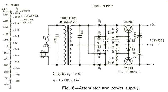
Fig. 6--Attenuator and power supply.
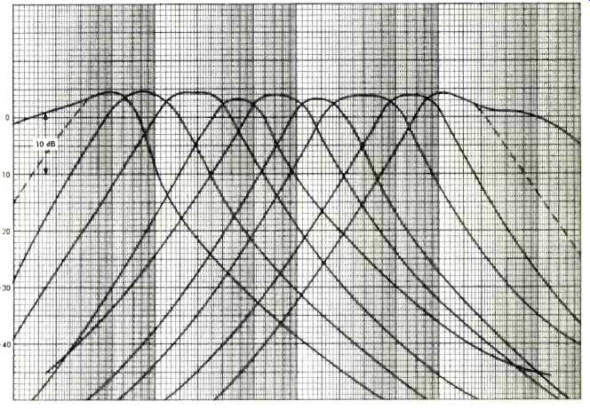
Fig. 7--Band frequency response characteristics.
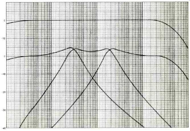
Fig 8--Frequency response when set flat (top) and when used as an electronic
crossover.
The results of the room equalizer are shown in Fig. 7. Notice that the bands don't all have the same percentage bandwidth, nor are the skirt characteristics all identical. This is because of the inevitable variation in component values. The curves are all very good for-20 decibels or so, and that is what matters. When used as a crossover network, Fig. 8 gives the characteristics. Figure 8 also shows the output frequency response curve when all nine bands are set "flat." The result, flat within 0.25 decibel, is gratifying and proof that it all works.
The distortion curves for a 1 kHz sine wave input and flat output are shown in Fig. 9. This also shows the effect upon distortion of boosting the upper three bands by 12 decibels with a 1 volt 1 kHz input. This boosts the distortion as the bands in which the harmonics of the 1 kHz input fall are being emphasized. The distortion is still acceptably low.
With the input open circuited, the noise is 200 microvolts rms. Short circuited it is 150 microvolts rms. The noise is mostly in the form of spikes up to 1.5 millivolts peak. This is referred to as "popcorn noise" and is a characteristic of many operational amplifiers such as the 741C. At any rate, this amount of noise is 74 decibels below a 1 volt signal, so it's rather academic.
If used as a crossover network this design is correct for all loudspeakers mounted on the same plane and as close to each other as possible. This is because the filter has already corrected for the phase shift between loudspeakers. Especially get the midrange close to the woofer.
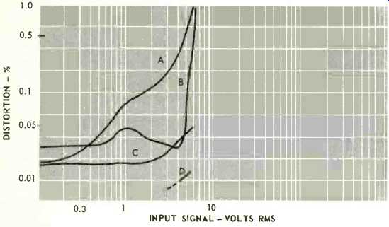
Fig. 9--Distortion components versus level: A, 2nd harmonic with boost; B,
3rd harmonic with boost; C, 2nd harmonic, flat response, and D, 3rd harmonic,
flat response.
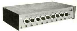
Fig. 10--View of the completed unit.
Figure 10 is a picture of the unit. The input and output are at the lower and upper right. The three outputs next to them are, from top to bottom, for the tweeter, mid-range, and woofer when used as an electronic crossover. The knobs or at least the skirts, are homemade. Such knobs are, of course, commercially available. Bond paper is glued to washers, marked with the proper numbers, and then glued to the rear of regular knobs. Below each knob is the output from each channel.
Are the results worth the effort? I think so. One thing about such a room equalizer is that it can make almost any speaker system sound like any other. This doesn't mean that it can make a poor loudspeaker into a good one, because it doesn't do anything to improve the transient response of a speaker system. (Or reduce distortion, coloration, etc. -Ed.) But if you like a bit of presence, dial in some more 2-4 and/or 4-8 kHz signal. If you're a bass buff, put in some bass below 60 kHz. Once you determine the equalization you want, you can design the proper circuit and build it into the system. Or, if you like knobs you can leave the equalizer in the system.
(Audio magazine, Sept. 1972)
Also see:
Equalization of Sound Reinforcement Systems (Nov. 1972)
Psychology of Sound Reproduction (June 1972)
= = = =