One of the more commonly used concepts in sound reinforcement, recording, and reproduction and one which often causes a great deal of confusion is the microphone sensitivity rating. This article will examine the various methods used beginning with the first principles, in order to provide a clearer understanding of what the rating systems are all about.
From our familiar experience, one of the most common manifestations of sound is the human voice. When speech sounds leave the mouth at a normal speaking level, the frequency components around 100 hertz cause a to-and-fro displacement of the air molecules which amounts to about 1/1,000 inch. This displacement diminishes with distance from the speaker, and at a distance of about 10 feet, it is reduced by about 60 times and the molecule displacement is 1/60,000 inch. The displacement can be reduced again by a factor of 200 before it becomes undetectable by the human ear. At this threshold level, when sound is just barely discernible, the displacement is about 1/10,000,000 of an inch.

The voice frequency components around 1 kHz cause displacements which are about 1/10 of the above, while frequencies around 2 to 4 kHz cause displacements in the order of 1/10 the diameter of an air molecule! While these figures are indeed interesting, displacement amplitude is not used directly in sound work. Instead, another relationship of air with sound is used.
What Mikes Measure
A microphone is an electroacoustic transducer used to convert acoustic energy into electrical energy. Microphones convert the periodic variations in air pressure into proportional variations of current or voltage. Let us therefore consider some facts concerning air pressure variations before we get into the microphone sensitivity ratings, and make some basic definitions as well.
Sound waves cause variations in the physical properties of air. These properties are air pressure, particle velocity, pressure gradient (rate of pressure change), density, temperature, intensity (flow of energy), and static pressure build-up at a reflecting surface. In order to gain a knowledge of the strength or magnitude of a sound wave, we have to measure one or more of these physical properties. The most fundamental property from a physicist's point of view is intensity, and this is defined as the flow of energy per unit time in a specified direction through a unit area perpendicular to the direction of flow. This is a very difficult measurement to make. The easiest property to measure is pressure, which is particularly fortunate because microphone output voltage is directly proportional to sound pressure. Being able to express a sound wave in terms of pressure units facilitates the relationship between sound waves and microphone output.
Sound wave pressure is expressed in units of force per unit area. The unit of force is the dyne. One dyne is a force of such magnitude as will cause a mass of one gram to acquire an acceleration of one centimeter per second per second. The unit of area is the square centimeter, which is a square one centimeter on each side. Because pressure is defined as force per unit area, it is expressed in dynes per square centimeter, and it is written dynes/cm^2. Sometimes you encounter the term microbar, which will cause no confusion if it is kept in mind that this term simply means one dyne per square centimeter.
We are now in a better position to talk about sound pressure in a more exact way, but it might be well to pause for a moment and consider the sound pressures found in our everyday experience and surroundings. Normal atmospheric pressure at sea level is about 1,000,000 dynes per square centimeter. Upon this steady or static pressure are superimposed the sound wave's molecular displacements.
At the threshold of hearing, where sound is just perceptible to the ear, the sound air pressure due to molecular displacement is 0.0002 dynes per square centimeter. The highest tolerable sound pressure, that is where sound becomes painful, is typically 640 dynes per square centimeter. This is called the threshold of pain. The sound pressure resulting from a normal speaking male voice at a distance of 12 inches from the mouth is about 10 dynes per square centimeter, while the pressure right at the same speaker mouth is about 100 dynes per square centimeter.

Rating a microphone or finding microphone sensitivity means expressing the output voltage or output power from the microphone as a function of a certain acoustic excitation or pressure. This procedure results in an unambiguous and reproducible method, with results that allow comparison between different microphones from a given manufacturer or between microphones from different manufacturers.
Intensity and Pressure
It now is necessary to determine how sound pressure varies with distance from the sound source. Sound intensity has been defined as the rate of flow of energy per unit area.
The unit of sound intensity is 1 erg per second per square centimeter and is written erg/sec/cm^2. The intensity represents the power in the wave so that intensity can also be expressed in watts per unit area which is the square centimeter. In other words, intensity is power transmitted per unit area. From a consideration of the energy properties in a sound wave, the intensity is given by:
lo = P^2/Ra watts per square centimeter (1)
where lo = intensity in watts/cm^2,
P = sound pressure in dynes/cm^2, and
Ra = acoustical resistance and is given by Ra = pc,
where p = density of air in grams/cm^3, and
c = velocity of propagation of sound in air in centimeters per second.
At normal atmospheric pressure of 1,000,000 dynes/cm^2 and at a normal temperature of 20°C, p = 0.0012 grams/cm^3 and c = 34,400 cm/sec. Their product is 42 and equation (1) becomes:
lo = p^2/ 42 watts/cm^2 (2)
Sound intensity decreases inversely as the square of the distance according to the relationship Io = Pa/ 4r^2 (3)
where Pa = rate of production of sound energy at the source (acoustic power).
r = distance from the source.
lo is seen to be power per surface area of a sphere because the wavefront expands spherically as it moves away from the source. Since the total energy in the wave must remain constant, the energy per unit area must decrease as the wavefront expands.
Equating (1) and (3)
Pa/4r^2 = P^2/Ra so that Ra Pa = P^2 4 r2,
from which P = 1 Pa Ra/4r (4)
We now see that intensity is inversely proportional to the square of the distance r from the source (equation 3) and that pressure is inversely proportional to r (equation 4). The decay of sound pressure and intensity with distance r from the source is shown in Fig. 1. It is interesting to note that the decrease of sound pressure is much more rapid when the distance is small, and that outside a range of about four feet, the rate of decrease is much less. Since the output from a microphone is proportional to the pressure, it is seen that the electrical output will vary in a like manner. At normal microphone speaking distances, the output varies greatly with small changes in distance, yet the microphone will pick up background sounds at a surprisingly even level at what appears to be widely varying distances from the source.
The concept of acoustic power is occasionally encountered in the literature, so we should note some typical power levels found about us. The rms speech power emitted by a speaker at normal conversational level is about 10 microwatts acoustic power. When a person speaks as loudly as possible, the power rises to about 200 microwatts, and when shouting, to about 1,000 microwatts. When whispering, the speech power is only about 0.001 microwatt. The power corresponding to the threshold of hearing (where the sound pressure is 0.0002 dynes/cm^2) is 10^-16 watts per square centimeter.
Relative Levels
So far, we have been talking in terms of absolute values of sound pressure and intensity. In sound work, intensity and pressure levels are usually given with respect to some reference or standard level, and the ratio of the actual value to the reference value is given in decibels.
Acoustic intensity level is the average rate of sound energy transmission through a unit area referred to an arbitrary intensity usually specified to be 10^-6 watt/cm^2, with the result is expressed in decibels. The expression for the intensity level is similar to the expression for the power ratio in decibels with which we are all familiar, thus
I, = 10 log I/lo decibels (5)
I, = intensity level,
I = sound intensity, and
lo = reference intensity (as in equation 1) and is 10^-16 watts/cm^2 as an arbitrary value.

Fig. 1--Intensity and pressure vs. distance.
Sound pressure level is the effective sound pressure at a point in the medium, referred to an arbitrary reference pressure usually taken to be 0.0002 dynes/cm', and expressed in decibels. The expression for pressure level is similar to the expression for voltage ratios and is:
SPL = 20 log Pe/Po decibels (6)
where SPL = sound pressure level,
Pe = effective sound pressure in dynes/cm^2, and
Po = reference sound pressure and is 0.0002 dynes/cm^2.
Note that the reference levels in (5) and (6) are those levels occurring at the threshold of hearing and that 0.0002 dynes/cm^2 is equal to a power of 10^-16 watts/cm^2.
By what we have seen so far, we note that any sound pressure can be stated as so many decibels above the defined threshold of hearing reference level. This relationship forms the basis for such statements as "the threshold of pain is 140 dB," "the rustle of leaves is 10 dB," "ordinary conversation at three feet is 65 dB," etc. Table I shows some of these typical values.
The following brief example will show how the table is constructed. We know that the sound pressure level for ordinary conversational speech is about 10 dynes/cm^2 at a distance of one foot from the mouth. Referring to Fig. 1, at a distance of three feet the pressure has decreased from a relative value of 5 at the one-foot distance to about a value of 2 at the three-foot distance. The value at three feet is therefore 2/5 times the value at one foot. The value at one foot is 10 dynes/cm^2, so that the value at three feet is 2/5(10) = 4 dynes/cm^2. From equation (6), SPL = 20 log 4/0.0002 = 66 decibels. This is the value given in Table I for conversation at three feet.
Deriving Sensitivity Ratings
There are basically two methods by which microphone sensitivity is rated, in terms of voltage or in terms of power.
Within these two main categories are several different methods in common use. These are listed below.
1. Open-circuit voltage output relative to a reference voltage level for a sound pressure of 1 dyne/cm^2. The result is expressed in dBV where the V means that 0 dB is taken at a 1 volt level.
2. Open-circuit voltage output relative to a reference voltage level for a sound pressure of 10 dynes/cm' expressed in dBV.
3. Voltage output relative to a reference voltage level for a sound pressure of 1 dyne/cm^2 when the microphone is connected to a 40,000-ohm terminating resistor. The result is expressed in dBV.
4. Output power relative to a reference power level for a sound pressure of 1 dyne/cm' expressed in dBm where the m means that 0 dB is 1 milliwatt.
5. Output power relative to a reference power level for a sound pressure of 10 dynes/cm^2 expressed in dBm.
6. Output power relative to a reference power level for a sound pressure of 0.0002 dynes/cm^2 expressed in dBm. The result is called Gm and is the EIA microphone sensitivity rating.
Unfortunately, there is little mutual agreement among the microphone manufacturers as to which rating system is preferable, and manufacturers have employed one or more rating systems for their products. Often, the manufacturers utilize the voltage output rating for high impedance microphones and the power rating for low impedance microphones. Among the voltage output ratings, method 1 is the more popular, and among the power output ratings, method 5 is the more popular. Method 6 is also used by many manufacturers.
Voltage Method
When the microphone response is given in terms of output voltage, the open-circuit (unloaded or unterminated) voltage is given relative to a reference of 1 volt for a 1 dyne/ cm^2 sound pressure and is the more commonly used system for rating high impedance microphones, as explained above. The result is expressed in decibels and is given by n = 20 log E/P (7)
where n = response in decibels,
E = open-circuit voltage in volts,
P = sound pressure relative to 1 dyne/cm^2, and
P = Pe/Po (8)
where P = sound pressure relative to 1 dyne/cm^2,
Pe = actual sound pressure in dynes/cm^2, and
Po = reference sound pressure and is 1 dyne/cm^2.
As an illustration of the rating method, consider a microphone that delivers a voltage output of 0.1 millivolt for a sound pressure of 1 dyne/cm^2. Then:
n = 20 log [0.1 x 10^-3]/1 = -80 dBm.
Now suppose that the sound pressure is increased to 10 dynes/cm'. Since the voltage response is linearly proportional to the pressure, we should expect the voltage to be 10 times as much or 1 millivolt. Under these conditions
n = 20 log [0.1 X 10^-3 ] /1/1= 80 dBm.
One of the beauties of the rating system is that it is independent of the test pressure level and is a property of the microphone itself. Of course, when testing or rating the microphone, the standard pressure is applied. The example clearly illustrates the value of the system when different microphones are compared.

Table I--Sound vs. relative levels above defined threshold of hearing.
When a microphone sensitivity is given as -80 dBm in a catalog, the actual output voltage can be found by calculating it from (9).
dBm = 20 log Eref/Eout
80 = 20 log [1/Eout] from which Eout = 0.0001 volt.
Remember that this is an open-circuit (unloaded or unterminated) voltage. When the microphone is connected to a terminating or load resistor, usually the input resistor of a preamplifier, this voltage will be less. In the case where this input resistor is the same as the microphone resistance, the voltage will divide equally across each resistor, as shown in Fig. 2. The voltage across the load resistor will be half the microphone open-circuit output voltage, which amounts to a 6-dB voltage loss. In practice, most high impedance microphones are not terminated with a resistance equal to the internal or nominal resistance. Usually the terminating resistance iÄ much higher in value. Under these conditions, the loss of available microphone open-circuit output voltage will be less than 6 dB.
The voltage loss due to terminating a microphone with a finite resistor is called the voltage loss due to the coupling factor, which is found from the following relationship:
Coupling factor = 20 log Ri/R+Ri (10)
where Ri = terminating or amplifier input resistor and
R = microphone resistance given by manufacturer.
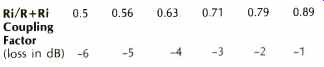
Table II--Voltage loss in dB for various ratios of input impedance and mike
impedance.
Typical values of the Coupling Factor are given in Table II. A microphone will occasionally be rated using method number 2. In the example illustrating the use of method number 1, the microphone was seen to deliver 0.1 millivolt output for a 1 dyne/cm^2 applied sound pressure (or 1 mV output for 10 dynes/cm^2) and reference level of 1 dyne per cm^2. If the reference is 10 dynes/cm^2 as for method number 2, using (7) and (8) with Po = 10 dynes/cm^2 will yield a sensitivity rating of -60 dBm. This is shown as follows:

Therefore, to convert from method 1 to method 2, merely add 20 dB. Conversely, to convert from method 2 to method 1, subtract 20 dB from the given rating sensitivity. These conversions are useful when comparing microphones from different manufacturers who use different ratings.
Power Method
When the microphone response is given in terms of power, the power output is given relative to a reference of 1 milliwatt and relative to a sound pressure level of 10 dynes 6 per cm^2. This method always assumes that the microphone is connected to a matched load. This is the most commonly used method for rating low impedance microphones and the result is expressed in decibels.
Consider a microphone connected to a matched load resistor. When the load resistor R1 in Table II is equal in value to the microphone resistance, half the open-circuit voltage output appears across the resistor. Under these conditions, the voltage across Ri is 1E. The power in the load resistor is found from W=E^2/R. In our example
W = (1/2E)^2/R = E^2/4Ri watts (11)
In order to express the power in decibels, we take the log of the power ratio according to the well-known relationship dB = 10 log W/Wo (12)
where W = power in the load as found from (11) and Wo = reference power level and is 0.001 watt.

Table III--Nominal microphone impedances vs. rating impedances.
Taking the reference power level as 0.001 watt (1 milliwatt) is in accordance with the definition for microphone sensitivity by the power method. Also, according to the definition, E must be taken relative to the reference sound pressure level of 10 dynes/cm^2. The relation of E to sound pressure P is E/P,
where E = microphone open-circuit voltage output and P = Pe/Po as in (8).
where Pe = actual sound pressure in dynes/cm^2 and Po = reference sound pressure and is 10 dynes/cm^2.
Substituting these foregoing relationships into (12) where (E/Pe 2 W Poi and 4 Ri Wo = 0.001 results in dB (E10 ) 2 = 10 log Pe l 4 Ri
0.001
Which simplifies to dB = 20 log Fe
10 log Ri + 44 (13)
from which the sensitivity rating is found directly. This method is also called the open circuit power or effective output level.

Fig. 2--Voltage loss when microphone impedance is equal to terminating impedance
(usually the input resistor of a preamp or mixer).
In (13), Ri is the microphone nominal impedance as given by the manufacturer in the catalog description. When evaluating (13) to find the microphone rating, the manufacturer applies test pressure Pe, measures the voltage output E, and inserts the rating impedance into the formula to calculate the answer. The rating impedance for use in this determination is not the catalog nominal impedance but the impedance as found from Table III.
Equation (13) is based on a reference pressure level of 10 dynes/cm^2. If the reference pressure level is taken as the threshold of hearing where it is 0.0002 dynes/cm^2, then the expression for the microphone sensitivity rating becomes dB = 20 log 10 log Ri 50 (14)
And is called the Gm microphone system rating.
The difference between (14) and (13) is 20 log Pe
10 log Ri + 44 (20 log Fe
10 log Ri 50)
= 94 db.
Therefore to convert from Gm to method number 5, add 94 dB. To convert from method 5 to Gm, subtract 94 dB.
System Gain
When a microphone, rated in terms of voltage, is connected to an amplifier which is rated in decibels of voltage gain, the output of the combination can be easily found from System Gain = microphone rating in dBV + coupling factor + amplifier gain in dBVg, where dBVg is the amplifier voltage gain in decibels.
For example, consider a microphone with a dBV rating of -58 dB connected to an amplifier input with an input resistance equal to the microphone impedance and a voltage gain of +80, which is typical. The coupling factor is-6 dB, and the system gain is then:
S.G. =-58-6 +80 = +16 dBV
where 1 volt is taken as 0 dB (that's what the V in dBV means) so that +16 dBV is equal to 6.3 volts.
It should be noted that the calculated output applies only when the rated sound pressure (for example, 1 dyne/cm^2 using method number 1) is applied to the microphone. At other sound pressures, the voltage is proportional to the sound pressure, as we have seen. Thus, if the microphone is used with a normal conversational voice at the nominal 12 in. distance, the applied pressure will be 10 dynes/cm^2 and the voltage will increase by a factor of ten. Precautions should be taken, however, to see that the amplifier does not overload.
When a microphone, rated in terms of power, is connected to an amplifier whose gain is expressed in decibels of power gain, the output of the combination can be found from
System Gain = microphone rating in dBm + amplifier gain in dB.
For example, consider a microphone power rating of -60 dBm connected to an amplifier with a power gain of+40 dB.
Then S.G. = -60 +40 = -20 dBm where -20 dBm = 0.00001 watt.
If the output load resistance is 600 ohms, the voltage across the load will be 0.077 volts.
The Gm sensitivity rating is used most frequently when the sound system rating includes the acoustic output from a loudspeaker at the output of the system. Otherwise the Gm rating is converted to method number 5 by adding 94 dB as has been explained.
Actually, the easiest way to figure system gain when confronted with microphones rated in dBV and amplifiers rated in dB of power gain is to convert the amplifier power gain into the equivalent voltage gain.
It is, of course, possible to convert a given microphone voltage rating to the equivalent power rating from
20 log E/P 10 log Ri + 44
which is the power rating response where 20 log E/P is the voltage response, as in equation (7). For example, if we have a microphone with a dBV rating of-70 dB and Ri is 150 ohms, then:
dB =-70-10 log 150 + 44 =-47.76 dBm.
If the foregoing principles are kept in mind, converting from one rating system to another will be facilitated and valid comparisons can be made between the microphones produced by the different microphone manufacturers.
(Audio magazine by Alfred Lorona)
Also see:
Miking With The 3-Point System (Dec. 1975)
Miking the PRO Way (Nov. 1977)
Time Delay for Ambience by Len Feldman (Dec. 1976)
= = = =