
Manufacturer's Specifications:
System Type: Three-way, vented box system.
Drivers: Two 6-in. cone woofers, 3 1/2 in. cone midrange, and 1-in. soft dome tweeter.
Frequency Response: 60 Hz to 18 kHz, ±3 dB, on axis.
Sensitivity: 91 dB, ±0.5 dB, at 1 meter, with 2.83 V rms applied.
Crossover Frequencies: 600 Hz and 6 kHz, both 24 dB/octave, phase-compensated within 30°. Impedance: 4 ohms nominal, 2 ohms minimum.
Nominal Power Rating: 80 watts below 600 Hz, 50 watts from 600 Hz to 6 kHz, 30 watts above 6 kHz.
Recommended Amplifier Power: Minimum of 100 watts per channel.
Dimensions: 22 in. W x 10 3/4 in. H x 13 in. D (55.9 cm x 27.3 cm x 33 cm).
Weight: 50 lbs. (22.7 kg) each.
Price: $2,400 per pair in oiled walnut (BBSM-6F) or black utility (BBSM-6); optional BWI-0410 bi-wire cables, $446 per pair.
Company Address: 2696 Lavery Ct., Newbury Park, Calif., 91320, USA.
Westlake Audio is best known in the professional sound market, where they are a major supplier of monitors for recording studios. Westlake Audio's extensive monitor line consists of 15 systems ranging from the small, $1,600/pair BBSM-4F two-way direct-radiator design up to the massive, five-way SM-1F that can be purchased complete with electronic crossovers and pedestal for $50,000 per pair! I evaluated the third system in Westlake's monitor line, the BBSM-6F direct-radiator system, which represents their first entry into the consumer market. According to the specification sheet, the BBSM-6F has been designed for "wide bandwidth, low IM distortion, good power handling, pinpoint stereo imaging, and a coherent wavefront" The most distinguishing feature of the BBSM-6F is its use of dual woofers in a horizontal, side-by-side, configuration. This configuration is common to all of Westlake's monitors and is primarily driven by the desire of most studios to have a monitor that has ample low-frequency acoustic output but is mounted in a box that is wider than it is tall, to fit their space requirements.
The BBSM-6F has a tweeter centrally mounted, above the midrange, and is flanked by the two woofers and their associated vented-box ports. Its totally symmetrical design eliminates the need for dedicated right and left systems.
The front-panel driver placement of the BBSM-6F facilitates the speakers' use as so-called "near-field" or "close-field" monitors in the studio. Recording engineers typically will place small monitors (believe it or not, these systems are quite small compared to typical behemoth studio monitors) on the top rear of the recording console, which places them within only 2 to 3 feet of the listener. Westlake Audio claims that you can even listen to the BBSM-6Fs as close as 18 inches away without sacrificing any of the system's imaging qualities.
The enclosure is fairly large and quite heavy, considering the size of the woofers. Most of the crossover is mounted on the detachable rear panel of the BBSM-6F, with the remaining portion behind one of the woofers. Connection is made through a large barrier terminal strip on the rear of the system. The high- and low-frequency portions of the crossover are separately connected to the terminal strip, to facilitate bi-wiring. Westlake Audio sells a fairly extensive line of single and bi-wire cable assemblies for use with their systems. The review samples were supplied with a set of 10 foot bi-wire cables using 4-AWG conductors! Removing the system's drivers revealed a tight-fitting, well-constructed enclosure using all 3/4-inch-thick medium density fiberboard. Diagonal braces are used inside both ends of the enclosure to strengthen the side walls. The midrange is housed in a separate enclosure attached to the rear panel of the main enclosure by a brace to minimize vibration. All inside surfaces of the enclosure are covered with thick fiberglass; the midrange enclosure was completely stuffed. Curiously, the magnetic pot structures of all the drivers were completely covered with a rubber-like adhesive or damping material similar to a silicone compound used for caulking bathtubs.
Removing the cabinet's rear panel (which is attached by 21 screws!) exposed the main part of the crossover, which is constructed point-to-point on the rear panel and takes up most of the panel's area of 9 x 20 inches. This complex crossover consists of 30 parts: 10 inductors, 11 capacitors, and nine resistors. All inductors are air-core. Most capacitors are high-quality, ±5% Solen brand parts, the largest of which is a 200-µF unit 2 1/4 inches in diameter and 4 1/4 inches long! The high-frequency portion of the crossover is wired on a hardboard panel separately mounted behind the right woofer. The crossover of the BBSM-6F is one of the largest and most complex I've seen, second only to the extremely large network of the Thiel CS5 (reviewed February 1991). All connections to the drivers consisted of stranded, 12 and 14-gauge hookup wire that was soldered to the driver terminals rather than attached by clips. However, in a number of places in the crossover, the workmanship left some thing to be desired. Many solder connections were not mechanically secure and were held only with solder. When I removed the rear panel, one set of leads connecting the hot terminals of the woofers to a terminal strip on the crossover board became unattached due to a cold-solder joint.
The crossover consists of a sixth-order, low-pass filter (three capacitors and three inductors) driving the woofers and a fourth-order, high-pass filter driving the midrange.
The 6-kHz crossover was formed by a sixth-order low-pass for the midrange and an eighth-order high-pass for the tweeter (four series capacitors and four shunt inductors to ground)! The manufacturer did not state the crossover design philosophy except to mention that high-order roll-offs were used for all transitions.

Fig. 1--One-meter, on-axis, anechoic frequency response, for an input of
2 watts into 4 ohms (2.83 V).
Measurements
Figure 1 shows the anechoic, on-axis, equivalent 1-meter frequency response, smoothed with a 10th-octave filter, for 2.83 V rms input (2 watts into the rated 4 ohms). The curve was taken at 2 meters and referenced to a distance of 1 meter; the microphone was normal to the enclosure's front surface, midway between the midrange and tweeter (which happens to correspond to the actual center of the box's front panel). Also shown is the effect of the grille on the response. The grille added significant deviations in the response above 1 kHz of about +2, -3 dB, with a boost in the range from 1 to 3 kHz and a depression between 3 and 7 kHz. Interestingly, I noted that Westlake Audio's instructions recommend that the grille be removed for calibrated accuracy and not to "disturb dispersion and frequency response." I agree! All other tests were made with the grille removed.

Fig. 2--On-axis phase response and group delay, corrected for tweeter arrival
time.

Fig. 3--One-meter, on-axis energy/time curve, measured with the grille off.
Without the grille, the curve in Fig. 1 fits within a commendably flat window of about ± 1.75 dB from 60 Hz to 18 kHz, which is significantly better than the manufacturer's rating! Note, however, that with the grille on, the curve more or less equals the manufacturer’s rating. The curve exhibits some roughness above 1 kHz, with a falling response above 15 kHz. Averaging the axial response, over the range from 250 Hz to 4 kHz, yielded a sensitivity of 90.6 dB, essentially equaling Westlake Audio's 91-dB rating. The two systems were quite closely matched, within ±0.5 dB from 100 Hz to 20 kHz.
Figure 2 shows the axial phase and group-delay measurements of the system, corrected for the tweeter's arrival.
The phase response exhibits a moderate total phase rotation of about 290° between 1 and 20 kHz. A comparison of the average group delay of the midrange (2 to 6 kHz) to the tweeter's range (10 to 20 kHz) indicates that the midrange driver lags the tweeter by about 0.15 mS. Although this time offset is fairly short, it is nearly one wavelength at the relatively high, 6-kHz crossover.
The energy/time response of the BBSM-6F is shown in Fig. 3. Because the linear sweep from 200 Hz to 10 kHz is roughly centered over the 6-kHz crossover, the main peak at 3 mS contains roughly equal contributions from the midrange and tweeter. The 90-dB main arrival at 3 mS is quite compact and only exhibits broadening at levels below 70 dB SPL, with a couple of lower level returns between 3.8 and 4.2 mS. A perfect energy/time response curve would appear as a single sharp spike centered at 3 mS, with a width of about 1 mS at the base (50-dB line) and tapering to a rounded point at the top.
A high-level, low-frequency sine-wave sweep revealed no significant cabinet side-wall resonances. A comparison of the woofer's excursion with the port open and covered by hand demonstrated that the port reduced the woofer's excursion a good 60% at the 42-Hz Helmholtz box-resonance frequency. The woofers did exhibit significant dynamic offset in the range from 70 to 160 Hz (also between 25 and 36 Hz) above 8 V rms, where the cones displaced outward. In addition, at 34 Hz with levels above 10 V rms, the low frequency drivers would go into a strange half-frequency subharmonic oscillation mode, where the cone would visually vibrate at about 17 Hz. Presumably this nonlinearity was also related to the same problems that generate dynamic offset. Port noises were minimal at high drive levels. However, at high input levels at and near the 42-Hz box tuning, port, air velocity was very high. At 42 Hz, an input of 17 V rms generated port air blasts that would blow out a match 5 feet away. (Yes, I really tried this.) The woofers' linear excursion capability was a good 0.3 inch peak to peak, with an excursion limit of about 0.7 inch peak to peak, quite good for 6-inch woofers. The woofers overloaded gracefully at high levels, with no objectionable noises. The effective piston diameter of the 6-inch woofer (actual outside frame diameter was 6 3/4 inches) was about 5 inches (measured from the middle of the surround on one side to the middle of the surround on the other). The air moving capability of the two 6-inch drivers corresponds roughly to that of a single 8or 9-inch driver of the same excursion.
Figure 4 is a "3-D" plot of the BBSM-6F's responses on and off the horizontal axis. For a system with perfect off-axis response, all the off-axis curves would have exactly the same shape as the on-axis curve (the bold curve at the rear of the diagram), including any aberrations seen in the on axis curve. The curves seen here are fairly well behaved and indicate good, wide horizontal high-frequency coverage. The off-axis ridge between 1 and 3 kHz indicates some broadening of the polar response, presumably related to box dimensions.
The vertical response curves are shown in Fig. 5, with the on-axis response shown as a bold curve halfway between the front and rear of the plot. The white space in the middle of the graph indicates increased directivity in the upper crossover region, from 4 to 8 kHz. Only the on-axis and ±5° curves are relatively flat through this region; the high crossover frequency of 6 kHz is the main contributor to this problem. Not shown clearly in the graph is the system's very symmetrical up/down response behavior through the crossover region, which indicates that the tweeter and midrange are essentially in phase with each other. This means that even though the system is quite directional vertically throughout the crossover region, the directional lobe is aimed straight ahead (minimum lobing error), precisely as it should be.

Fig. 4--Horizontal off-axis frequency responses, taken from the front, around
the side, and to the rear of the speaker.

Fig. 6--Mean horizontal responses, derived from data of Fig. 4.

Fig. 5--Vertical off-axis responses, taken from below, up the front, and
to the top of the speaker.
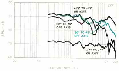
Fig. 7-Mean vertical responses, derived from data of Fig. 5.
Figures 6 and 7 show, respectively, the horizontal and vertical on- and off-axis response curves. The mean axial (+ 15° to 15°) horizontal response curve in Fig. 6 is quite flat and extended except for some high-frequency roll-off above 17 kHz and a slight dip in the region from 8 to 10 kHz.
The 30° to 45° mean response is fairly similar to the axial curve but exhibits a gentle downward trend above 2 kHz and a sharp roll-off above 12 kHz. The 60° to 75° off-axis response is much rougher than the previous two responses, with higher directivity below 1 kHz and a more rapid roll-off above 3 kHz. The similarity of the three curves through the area from 1 to 3 kHz shows the loss of directivity noted earlier in the "3-D' curves of on- and off-axis response.
Figure 7 shows the vertical responses of the BBSM-6F. The mean vertical axial curve (+ 15° to 15°) is rough between 1 and 4 kHz and has a hole at crossover, between 4 and 7 kHz. Examination of the individual curves that comprise the mean axial response (not shown) indicated that up/down behavior was quite symmetrical but that high side-to-side directivity made the responses beyond ±5° exhibit a hole at crossover. The lower curve in Fig. 7, an average of just the-5°, 0°, and +5° responses, is much smoother. This indicates that a listener must be within approximately ±5° of the axis vertically to hear a smooth response. The 30° to 45° response is significantly smoother than the on-axis averaged response but has greater high frequency roll-off. The 60° to 75° mean response exhibits even greater high-frequency roll-off coupled with a hole in the frequency range from 3.5 to 6 kHz.
The BBSM-6F's impedance, from 10 Hz to 20 kHz, is shown in Fig. 8. Immediately evident is the amplifier-punishing impedance low of 1.9 ohms at 140 Hz. Between 100 and 500 Hz, the system's impedance does not rise above 2.2 ohms! Only amplifiers with high current capability should be used with the BBSM-6F. The system's minimum impedance of 1.9 ohms, coupled with its passband maximum of 13 ohms (a ratio of 6.8), make the BBSM-6F very sensitive to cable resistance. To keep cable-drop effects from causing peaks and dips in response greater than 0.1 dB, cable series resistance should be limited to a (very low) maximum of about 0.026 ohm. This means that cable no smaller than 10 AWG should be used for a typical 10-foot run.
Figure 9 shows the complex phase plot of the B3SM-6F's impedance, over the range from 8 Hz to 30 kHz. The smoothly changing spirals indicate an absence of resonance problems. The impedance phase angle (not shown) reached a maximum of +39° at 28.8 kHz, which is above the audible range, and a minimum of 59° at the bass frequency of 72 Hz.
Westlake Audio supplied optional cables designed for bi-wiring (feeding the crossover's high- and low-pass sections with separate cables from the same amp terminals). An excellent recent engineering report by Fred E. Davis ("Effects of Cable, Loudspeaker, and Amplifier Interactions," Journal of the Audio Engineering Society, June 1991) prompted measurements of the two cables by comparing the voltages at the amplifier and speaker ends of the cable during a frequency sweep from 20 Hz to 20 kHz. The Straight Wire cable I ordinarily use has an almost linear attenuation of between 0 and 0.1 dB over the frequency range, with maximum attenuation at the BBSM-6Fs impedance minimums. In contrast, the Westlake Audio cable had a relatively low attenuation of about 0.02 dB up to 7 kHz, a slight boost of about 0.02 dB in the range from 2.5 to 5 kHz, and a roll-off above 7 kHz that reached -0.27 dB at 20 kHz.
This roll-off is due to the high inductance of the large 4 gauge wire used in this cable, and the 0.02-dB boost is due to resonance of this inductance with the capacitive reactance of the speaker system's input impedance.
The 3-meter room curve of the system, including both raw and sixth-octave smoothed responses, is shown in Fig. 10.
The BBSM-6F was located in the right-hand stereo position, aimed at the listening location, and the mike was placed at ear height (36 inches) at the listener's position. The system was swept from 100 Hz to 20 kHz with a sine-wave signal at 2.83 V rms (corresponding to 2 watts into the 4-ohm rated impedance). The parameters of the test sweep were chosen so that the direct sound plus 13 mS of the room's reverberation were included. The curve is fairly flat and extended except for some midrange emphasis between 480 Hz and 1.8 kHz and room-effect response roughness at lower frequencies.

Fig. 8-Impedance; see text.

Fig. 9-Complex impedance, showing reactance and resistance vs. frequency.

Fig. 10-Three-meter room response, showing both raw and smoothed data.

Fig. 11--Harmonic distortion products for the musical tone

Fig. 12--Harmonic distortion products for . the musical tone

Fig. 13--IM distortion on 440 Hz (A4) produced by 41.2 Hz (E1) mixed in one-to-one
proportion.
Distortion with increasing power of musical notes E, (41.2 Hz) and A2 (110 Hz) is shown in Figs. 11 and 12. No graph for A4 (440 Hz) is shown because the distortion products were below the measuring capability of my equipment.
The E1 (41.2-Hz) harmonic distortion data shows that full power second- and third-harmonic distortion reaches a significant 18% to 19%. At 41.2 Hz, 100 watts generates a loud 100.5 dB SPL at 1 meter. In the A2 (110-Hz) harmonic data shown in Fig. 12, tie second harmonic reaches a significant 14.1% at full power, with the third reaching only 1.5%. Interestingly, the third reaches an intermediate maximum of about the same level at a lower power level. At 110 Hz, the Westlake system generates a loud 1-meter level of 108 dB SPL at 100 watts.
The IM on a 440-Hz (A4) tone, created by an equal input level 41.2-Hz (E1) tone, is shown in Fig. 13. At full power, the distortion reaches a moderate 10%. After the sine-wave distortion tests, an examination of the crossover network revealed that the tests had severely overheated a resistor in the bass leg of the network. This resistor, a 0.33-ohm, 5-watt unit (marked R1 on the supplied schematic), is in series with the large 200-µF capacitor mentioned previously. Fortunately, the resistor continued to work and did not require replacement.
The system's short-term peak input and output power capabilities for tone bursts are shown in Fig. 14. The peak input power was calculated by assuming the measured peak voltage was applied across the rated 4-ohm impedance. At frequencies where the BBSM-6F's impedance is much lower than 4 ohms, the actual input power is higher.
The maximum peak electrical power-handling capacity of the BBSM-6F is shown in the lower curve of Fig. 14. Above 200 Hz, the power limit of my Crown Macro Reference amplifier was reached before the speaker's limit was reached. Between 70 and 160 Hz, the input power was limited by the dynamic offset of the woofers, where the cones would visibly move forward during the burst.
The upper curve in Fig. 14 shows the maximum peak sound pressure levels the BBSM-6F can generate. Also shown is the "room gain" of a typical listening room, which adds about 3 dB to the response at 80 Hz and 9 dB at 20 Hz. Above 600 Hz, the peak maximum output rises to a loud 126 dB! With room gain, a single BBSM-6F can generate peaks in excess of 110 dB SPL above 42 Hz, and 120 dB above 180 Hz. Even higher low-frequency peak levels can be expected for two systems operating in a standard stereo configuration.

Fig. 14--Maximum peak input power and maximum peak sound output vs. frequency
at 1 meter on axis.
Use and Listening Tests
Westlake Audio provides excellent use and setup information for the BBSM-6Fs. Their professional roots show in a series of very detailed application notes that cover everything from cabling and bi-wiring to setup information. An application note was even supplied for the proper procedures for driver replacement. The caliber and amount of technical information supplied in these notes exceeds any that I have received from other manufacturers.
In general, Westlake Audio recommends a fairly dead acoustical environment for the BBSM-6Fs. This includes treatment of all reflecting surfaces between the system and listener that might generate potential interfering acoustic signals. They state that the "best sound and imaging will usually occur when the speakers are focused directly at the listener." Detailed alignment instructions are included to ensure that the distances from each speaker to the listener's head are matched to within 1/2 inch. Fortunately, these setup instructions agree quite closely with the way I normally evaluate systems, with the possible exception of the dead environment.
The input connector of the BBSM-6F is a large, heavy-duty, four-terminal barrier strip with the high- and low-frequency portions of the system separately connected. Short, heavy-gauge wires with spade lugs attached are provided to connect these sections in parallel when the system is not bi-wired. Although Westlake Audio provided a well-constructed set of heavy-gauge cables for bi-wired operation, I did not bi-wire the systems for my listening. This was partly due to the results of the cable measurements mentioned previously as well as for convenience.
The review systems were supplied in a very good-looking oiled walnut finish with brown grilles. With grilles on, the systems are quite handsome, accented with a rectangular cutout on the lower right of the grille displaying a silver nameplate with black and red lettering. However, with grilles off, the systems take on a heavy-duty, business-industrial look that doesn't quite fit the domestic environment. I did all my listening with the grilles off, as Westlake recommends.
For listening, I mounted the speakers horizontally on stands (not provided), which placed them so that the center of each box was about 32 inches high. As this height was about 4 inches lower than I desired, I slightly adjusted the stands' feet to tilt the box axis upward, so that it was aimed at my head. The horizontal orientation of the boxes initially looked strange as compared to the normal vertical orientation of other similarly sized speakers.
Initial listening revealed a system that was significantly more sensitive than my reference B & W 801 Matrix Series 2.
The Westlake Audio BBSM-6Fs had good overall balance and excellent imaging; however, they had significantly less bass impact than the reference and a somewhat forward sound. The BBSM-6Fs just about equaled the high-frequency smoothness and extension of my reference but exhibited some midrange tonal differences that were not to my taste.
The BBSM-6F's excellent peak output and dynamic range capability were demonstrated very well on Hiroko Kokubu's Light and Color CD of Brazilian-style music (JVC VICJ61), which I recently brought back from Japan. The dynamic range and high-level cleanliness of the systems were demonstrated by their reproduction of Carl Czerny's four-hand piano works played by Tal and Groethuysen (Sony SK 45936). The Westlake speakers exhibited a smooth upper midrange and treble, which allowed me to follow very nicely the individual flute parts over the harpsichord and piano backing on the Rampal, Kudo, and Ritter CD of music by Telemann, Kuhlau, Bach, Mozart, and Doppler (Sony Classical SK 46482). The systems portrayed a very realistic room sound and reverberation decay on the same CD. Only slight tonal changes were evident on the pink-noise stand-up/sit-down test, with the change mainly occurring only in the stand-up position. The BBSM-6F's low-frequency output on third-octave band-limited pink noise was quite strong at 40 Hz and above. In the 31.5-Hz third-octave and below, the output was greatly diminished and was accompanied by noticeable cone motion and high out-of-phase port activity. In the 40-Hz third-octave, corresponding to the 42-Hz box tuning, high input levels generated port air blasts that could be felt at the listening position! Fortunately, although port air velocities were high, wind noise was not objectionable.
On appropriately recorded program material, the lateral imaging and soundstage presentation of the BBSM-6Fs were excellent. On high-level playback of jazz and rock 'n' roll, the speakers would really boogie! The high peak levels of drum rim shots and the like were rendered quite realistically. Reproduction of spoken male voice did reveal some upper midrange emphasis when compared to my reference systems.
In summary, the BBSM-6Fs deliver a number of important performance attributes in a relatively small package. These include high output capability, accuracy, precise imaging, smoothness, and even coverage. In addition, the Westlake Audio speakers work very well in situations where the listener has to be physically close to the systems, such as in small listening rooms and remote recording situations. On the downside, they require high-quality amplification that can drive low-impedance loads of only 2 to 3 ohms, along with minimum-loss cabling. Although these facts, coupled with the speaker's relatively high cost of $2,400 per pair, complicate a buying decision, the BBSM-6Fs do deserve serious consideration and evaluation by those requiring a relatively compact, high-performance loudspeaker system.
-D. B. Keele, Jr.
(Source: Audio magazine, Dec. 1991)
Also see:
Vandersteen 2Ci Speaker (Jun. 1992)
= = = =