|
|
Introducing a world-first performance breakthrough in tube power amp circuit design.
For 45 years I have been lamenting the impossibility of bias-stabilizing an over-driven audio amp. The grid current of attracted electrons always shifts the operating point to wards current cutoff until serious cross over distortion thoroughly spoils the fidelity. Coupling transformers are the obvious solution, but they limit negative feedback, take up space, and cost big money for two wideband low-distortion units, such as Sowters of England.
Well, not anymore. One day—during weight-training—I realized that in nearly all push-pull amplifiers the negative peak voltage swing on the grid is not actually doing anything useful because that tube is already cut off. Bingo. Connect the grid through an appropriate zener to earth, and the built-up electrons on the coupling capacitor will shoot to earth in spurts on the negative voltage peaks.
Yeah, it works, eliminating the high- drive-induced zero-crossing kink and giving more power to the voice coil, be cause now you can increase the drive beyond AB1 right into AB2! In fact, as my oscilloscope photos show, you can even choose a zener value to make the average grid voltage drift less negative(!) at high power, rather than more negative! Please yourself.

PHOTO 1 The completed tube amp.

PHOTO 2: An underview of the 550mm x 330mm 37kg behemoth showing a newly
installed preamp filter choke below the top left corner.
HOW IT WORKS
Figure 1 shows the basic schematic of the system. The plain diode D prevents the positive-swing grid drive from shorting to earth through the zener. Separate diodes are advised for parallel tubes. The resistor R reduces the transient load discontinuity seen by the driving valve, which can cause ringing around the feedback loop. Try about 1 k-ohm per grid, as with my 330-ohm for four grids.

FIGURE 1. Simple circuit mod.
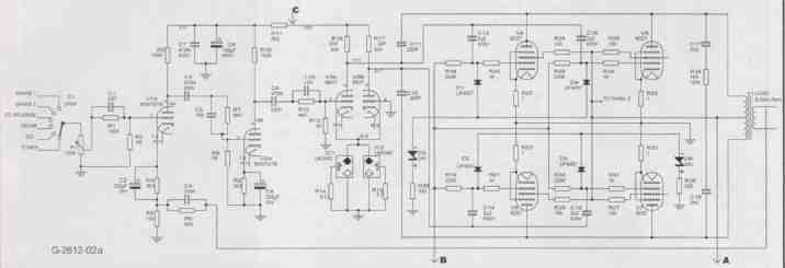
FIGURE 2a
Figure 2 (a, b) is thr full amplifier schematic included in the spirit of full disclosure, in the name of investigative research, where scrutineers want the complete picture.
Photo 3 shows clean soft clipping at over 60W RMS into a 5-ohm load on a nominally 8-ohm output. Previously only 40W had been available before developing a nasty zero-crossing kink, which sounds terrible on music because it happens thousands of times per second, in contrast to transient peaks being clipped infrequently. Photo 4 shows one 6DZ7 cathode current smoothly clipping at over 400mA (!) from a quiescent current of 50mA. Photo 5 shows the actual grid signal reaching overdrive to 4V, and clamping gently below -24V, as hoped, with the fixed-bias supply being -12V.
Switching off the 700Hz overdrive revealed that the average grid potential had dynamically stabilized at about -10V during that overdrive, which means nearly pure class A (-9V) during dynamic conditions! What a dream scenario for maximum sound quality. And plate power dissipation should not be a problem, because dissipation equals power input minus audio power output.
With a lesser zener, say -18V, you could actually drift from class AB to genuine A2, rather than AB2! I have not tried that, but I have tried upping the fixed bias to -19V, giving quiescent current of only 2mA, implying class B. The high-drive waveforms were still all virtually the same as above, confirming that class B low-drive was drifting to class AB2 in overdrive.
Very interesting, but this, of course, gave a rather thin sound quality at quiet levels. Historically, the problem has been the opposite: quiescent class A drifting to class B due to grid current charging the coupling capacitors, and giving a mushy gradual overload as your amp gets its zero-crossing current strangled off. Actually, cathode bias alleviates this problem by drifting down when the current falls, which is why many experimenters over the years have reported that cathode bias sounds better on music in spite of giving lower sinewave-test power.

PHOTO 3 Clean heavy overdrive output clipping beyond 60W, without the usual
shoulders that appear in RC coupled amps due to grid bias shaft, and sounding
like severe crossover distortion rather than subtle clipping.
PHOTO 4: The overdrive grid drive voltage, 5V/div, with 0V set at 2cm above center.
PHOTO 5: The quiescent grid voltage sitting at about -12V.
PHOTO 6: One 6DZ7 (twin E184) cathode current achieving over 400mA peak on overdrive There are eight 6DZ7s which is like sixteen E184s.
PHOTO 7: One 6DZ7 quiescent cathode current at around 40 to 50mA.

FIGURE 2b: Complete clamped-bias amp circuit.
WRAPPING UP
Well, there you have it. Anyone is welcome to use my dynamic-bias-clamp, which might soon sweep the tube amp board, pretty much as ultralinear did around 1954. If it’s taken half a century for the “next big tube thing,” better late than never. And, it is easily retro-f it- table to any existing HO-coupled push pull tube amp in just a few minutes.
For full benefit, a slightly lower load impedance would actually help, be cause then you could swing more peak current. To those concerned about accelerated tube-aging, I had, during my feed back stabilization adjustments (because 26dB is quite a lot of feedback), some high power oscillations at 150kHz, and later at 2Hz, causing overdrive so huge that I could hear one 18 lb output tranny ticking audibly at 2Hz. But everything survived, and the tubes were apparently unaffected, meaning same quiescent current, and still capable of 400mA peak.


The power response is -1dB at 7Hz relative to 60W. The output impedance is 0.2-ohm. I designed the 18 lb output transformers myself, 14-section coil, using the Radio Designers Handbook, and a retired army-tech wound them for me. I hand-painted the end-covers with Hammerite paint from England to achieve the unique kaleidoscopic color scheme.
Finally, I won’t be making the usual constructor’s fatuous comment on sound quality, such as “it sounds like Westinghouse 300Bs on steroids, and so on,” because we all know that every mother’s own baby is the most wonderful baby in the world anyway.
============