|
|
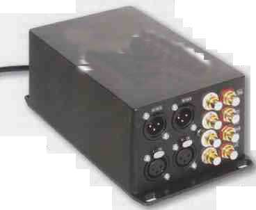
Let's build a better converter box to handle balanced/unbalanced devices...
When studying geography in grammar school, you learned that the Great Divide was the North American mountain range separating the watersheds that drain into the Pacific Ocean from those that drain into the Atlantic. Sometimes it feels as though we have a similar divide in the audio world, with the choice between balanced and unbalanced equipment interconnections.
The home market has been using unbalanced connections because they are less expensive and work well in most situations. You see an increasing number of pro-audio products with balanced connections that are reasonably priced and attractive alternates for home audio use. I use Behringer equalizer and speaker control units along with several amplifiers that all have balanced connections. They need to be integrated with the unbalanced devices that make up the rest of my system. The key is to use the proper method for those connections.
My interest in the balanced/unbalanced scenario was piqued by an excellent article about noise in audio circuits. It was based on information from a seminar that he attended given by Bill Whitlock. This article, a concise description of noise problems and their solutions, mentioned devices from IC-manufacturer THAT Corporation ( Milford, Mass.) that were based on Whitlock’s work. It also included an analysis of passive devices that can be employed in the quest for lower noise.

DEFINITIONS
There seems to be confusion regarding what constitutes a balanced circuit. People talk about two signal-carrying conductors instead of one, opposite signal polarities in a balanced configuration, and so on.
Bill Whitlock (president and chief of engineering, Jensen Transformers) has accurately defined “unbalanced”:
“An unbalanced input or output connects one of its signal conductors to ground and has a non-zero impedance at the other signal conductor.”
His correct definition of “balanced” L is: “A balanced input or output uses two signal conductors which have equal impedances to ground.”
Note that the key difference in these definitions is the impedance between each signal line and ground. The unbalanced circuit does have two signal lines and current does flow in opposite directions in the two lines, but one of them connects to ground. Therefore, the impedances are neither the same nor balanced. The balanced circuit has equal impedances to ground from each line.
Also note that there is no mention of equal voltages, because it is the impedance balance that is critical. Failure to maintain impedance balance on the signal lines is the root cause of common-mode failures with some circuit configurations.
An understanding of this is important because a true balanced circuit has a greater ability to reject common-mode signals, which are of the same polarity and magnitude on both signal lines. These signals represent unwanted noise interference that will degrade signal quality. Reduce those and you will have less noise to interfere with your signal.
A great introduction to the subject of noise, grounding, and safety in audio connections is the Journal of the Audio Engineering Society v43n6 (June 1995), which includes papers and reports by Neil Muncy, Bill Whitlock, Charles Atkinson, Philip Giddings, Stephen Macatee, John Windt, Cal Perkins, and Kenneth Fause that are a gold mine of important information. There are also citations to additional references. Copies of the individual papers in PDF form are available from the AES website. You can search for any articles by the volume and number, title, or author.
Probably the least effective method to connect balanced and unbalanced devices is to make adapter cables. This is generally not a good solution, but there are adapter cable designs that take into account the type of connectors and the direction of the connection (balanced-to-unbalanced or unbalanced-to-balanced). One of the best explanations of interconnects, with a table of different connections, is in a paper from Rane Corporation I have built cables using their tables and have obtained effective results in situations where noise is not a major factor.
SOLVING THE NOISE PROBLEM
With noise, reality sets in when two problems are introduced: improper connections of an XLR’s pin-1 to ground [ SMPTE RP134, EBU R50-1988, and IEC 268 part 12 all standardized that an XLR connector’s pin-1 is ground, pin-2 is the positive signal connection, and pin-3 is the negative signal connection—David J. Weinberg], and differences in the impedances of the two signal lines in a balanced circuit. This article does not address the pin-1 problem, which is covered in several articles in the previously-mentioned AES issue.
To reduce susceptibility to noise, high-quality transformers can retain common-mode rejection even with relatively high levels of impedance mismatch, due to their high common-mode input impedances. In addition, they can provide a high degree of voltage isolation where offsets exist be tween devices. Unfortunately, they are not inexpensive, and less-expensive versions often have severe performance limitations. As a result, many attempts have been made to develop active circuits that can be used as balance inputs and outputs.
At first blush, some of these active devices seem to offer ideal solutions. The Analog Devices AMPO3 precision unity- gain differential amplifier has a common-mode rejection ratio (CMRR) of 100dB at 0Hz (= DC), and a respectable 70dB at 20kHz. The amp has internal resistors balanced to within 0.002% to make this performance possible and free the equipment manufacturer from having to select precisely matched external resistors.
However, any output impedance differences from the driving equipment can destroy the performance improvement achieved by this precise on-board resistor matching. It does not take much of an imbalance to produce a large drop in CMRR A balanced system acts like a Wheatstone bridge, with the driver output impedances and receiver input impedances forming the legs of the bridge. If any of the impedances become out of balance, rejection drops. For example, for an input impedance of 5 k-ohm, a 1-k-Ohm) imbalance in the output of the driving circuit can cause a 60dB drop in CMRR.
The severity of the problem is minimized if the impedances of the bridge’s output and input sections are very different. The impedances in each line of the driving side, and of the receiving side, must still be closely matched for the rejection to be maximized. Low output impedances are common in driver stages, but high common-mode input impedances in receiving stages are not, generally due to noise concerns. Transformers are an exception, routinely having common-mode input impedances in the tens of megohms.
The products from THAT Corporation include newly developed input line receivers based on Whitlock’s work. Balanced- output drivers were also mentioned. There are two device families:
• The ‘InGenius’ family of line receivers uses a bootstrapping technique developed by Whitlock to feed common-mode signals back to the input to increase the common-mode input impedance while maintaining lower DC impedances These devices can provide many of the benefits of transformers without the cost penalty or extreme low-frequency losses.
• The InGenius family of line drivers uses a dual-feedback-loop design described by Gary K. Hebert that prevents excessive ground currents when clipping into single- ended loads. In cross-coupled output stages, that can lead to difficulties in the power supply and additional distortion.
PROJECT IDEA
These devices seemed to be the perfect Solution for a project I was formulating for copying many of my LPs to CDs. Part of the setup included the use of an equalizer to correct recordings that were either not tonally balanced to my taste, or used equalization curves other than RIAA. You can find a reference to EQ curves of old records using Google. You can find the settings needed when using an RIAA phono section to correct for the non RIAA curves, again using Google search.
First look up the code for the equalization curve of your recording (such as 500C-16 for Columbia LPs). Then look up that code in the second resource. In this example you need these corrections:
20Hz -8.0dB
40Hz -5.0dB
62Hz -4.5dB
100Hz -2.0dB
The plan was to run the output from my custom stand-alone RIAA phono preamp through my Behringer DEQ2496 equalizer into my computer’s sound card. In the analog domain, the Behringer only has balanced inputs and outputs. It would be fed from an unbalanced preamplifier and would feed an unbalanced computer audio card.
Therefore, the signal would undergo a transformation from unbalanced to balanced and then back to unbalanced in its journey from the phono cartridge to the computer sound card. Instead of using adapter cables to convert between unbalanced and balanced, as I had done in the past, it seemed time to “kick it up a notch.”
This application was a good way to test the circuits from THAT Corporation. The concept was to build a box that could take the unbalanced output of the phono preamp, convert it to balanced (using two THAT 1646 differential line- drivers) for the equalizer inputs, and then convert the equalizer output back to un balanced (using two THAT 1206 balanced line-input receivers) to feed monitoring headphones and the computer.
STARTING THE PROJECT
Any electronics project I have built started with an idea, moved to a schematic, then layout, construction, and testing. The concept part was made easy with these new ICs and their supporting datasheets.
Usually I draw the schematic by hand and then do the layout and build the project using perfboard and terminals. This time I tried another approach—find an easy-to-use PC software package that would enable me to produce a printed circuit board onscreen.
A web search led me to www.ExpressPCB.com, an Oregon-based company offering free tools that allow you to produce a schematic, check it for errors, link the schematic to a board-layout program, complete the layout, and electronically ship the results to them for circuit-board production.
Their schematic program (ExpressSCH) comes with a library of device components. You can also produce your own components either by modifying one of their existing components or by producing your own and storing them in a custom component library.
Although reasonably intuitive, it took a while for me to understand the production of a device from scratch, especially the placement of leads, connections, and the numbering scheme. Their manual will guide you through the process of producing a schematic. One subset of that manual is a guide to help you when making schematic components to use in the program (that part is avail able from them in PDF format at www. ExpressPCB.com).
In addition to the library of components, the program also comes with a library of symbols. As with components, you can make custom symbols and store them in a custom symbol library. I especially liked the use of ports, which are symbols indicating a connection that can be for signals, power, grounds, and so on. Using them eliminated the need to show a lot of repetitive connecting lines on the schematic.
For example, you could use a symbol on the schematic for a +15V DC supply connection wherever you needed one, without running a line back to a single supply point. Because the schematic will later be linked to a PCB layout program, the ports will indicate connections that need to be made on the board without actually showing the connecting links as lines. This resulted in a very clean schematic that looked more like a group of functional blocks than my freehand drawings. It also allows you to save your frequently used components and symbols in a library called Favorites that minimizes search effort when drawing the schematic. Once learned, the program was quite effective. An additional bonus is a tool that checks for netlist errors such as pins that were not connected.
The Airborne line of drivers was developed to fill the gaps left by the industry in the use of exotic and unconventional material to reproduce sound. For example the use of real wood as a cone material gives you very natural and worm sound, the use of Bamboo which is very light and strong which translate in very fast reacting driver and the use of Carbon Fiber which is extremely light and strong gives you a very analytic and very detailed sound.
CIRCUIT DESCRIPTION
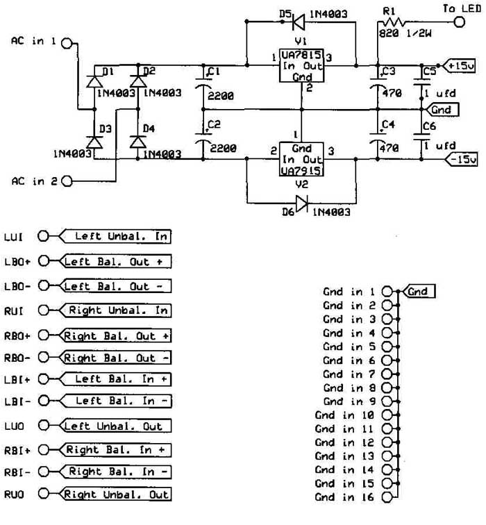
Figure 1 shows my completed schematic, including the power supply but less the power transformer (which is not mounted on the board). The power supply section takes the secondary output of a 34V AC center-tapped transformer, uses four diodes (D1 — D4) in a full-wave bridge configuration to rectify it, and filters it using capacitors C1 and C2. That DC voltage then passes through two IC regulators (Vi for the positive bus; V2 for the negative bus), and is further filtered using capacitors C3 — C6.
Diodes D5 and D6 provide protection for the regulators against reverse bias. Resistor R1 feeds power to a chassis-mounted power indicator LED. The transformer secondary’s center tap is connected to the circuit board’s ground.
For this project, where high levels of RF interference would not be a problem, I used a basic configuration for the un balanced-to-balanced and the balanced- to-unbalanced sections. If RFI is a problem, the ICs’ datasheets detail methods to reduce RFI without materially affecting common-mode rejection.
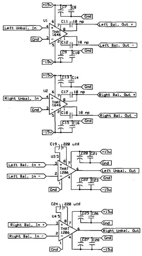
The active sections of the circuit are simple, as shown in the schematic. The unbalanced-to-balanced section of the left channel consists of U1 (the balanced- line driver), power supply bypass capacitors C7 — C10 mounted right at the IC leads, and two capacitors C11 and C12 that serve to reduce the output DC common-mode voltage to zero. It is repeated for the right channel using .U2.
The balanced-to-unbalanced section of the left channel consists of U3 (the balanced input line receiver), power supply bypass capacitors C20 — C23 mounted right at the IC leads, and capacitor C19 that provides the bootstrapping current to generate a very high AC common- mode impedance.
Again, these are simple circuits. If the circuits will be subjected to very high RFI or the possibility of electrostatic discharges, refer to the datasheets for suggestions on how to reduce those risks with minimal impact on common-mode rejection.


FIGURE 1: Unbalanced/balanced converter circuit.
Also note the ports for power, signal, and ground leads. The signal and some of the ground ports are connected to stand alone holes with descriptions indicating the functions of each port. The power supply positive and negative ports are directly connected to components, because no external input or output connections are needed.
Next, we’ll tackle construction and testing of this converter box.

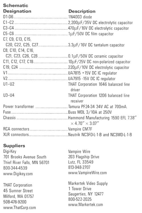
ABOVE: Parts List
Schematic
Designation | Description
REFERENCES
1. Gary Galo, “Grounding and System Interfacing,” January 2007 audioXpress
2. Bill Whitlock, “Interconnection of Balanced and Unbalanced Equipment,” Jensen Application. Note AN-003
3. Stephen Macatee, “Grounding and Shielding Audio Devices,” Rane Note 151.
4. Bill Whitlock, “A New Balanced Audio Input Circuit for Maximum Common-Mode Rejection in Real World Environments,” AES preprint.
5. THAT Corporation DataSheet, InGenius Balanced Input Line Receivers, www.ThatCorp.com.
6. Gary K. Herbert, “An Improved Balanced, Floating Output Driver IC,” 108th AES Convention, February 2000.
7. THAT Corporation DataSheet: “Outsmarts Balanced Line Drivers,” www.ThatCorp.com
Featuring the ultimate winding geometry (edgewise) for extremely short, low-loss signal transmission, extremely reduced residual-resistance (ESR), remarkable low residual-inductivity (ESL).
============