|
|
Presented below is an update of a classic output transformerless (OTL) tube amplifier of the 1950s.
I am not an electronics professional. I am a hobbyist. Although I have designed and built amplifiers and other electronic gear, most have been solid-state, and all have been for my own pleasure only.
I have been profoundly interested in electronics, especially audio electronics, since I was a freshman in college, when one day in the basement of my dorm, among the ping-pong and pool tables, an upperclassman set up his home-built high-fidelity system. It was in the days before the advent of stereo, and was composed of one single ported, unfinished plywood baffle, standing about 6’ high, housing what I think was an Altec Lansing 15” woofer with a midrange and a tweeter. He had a tube amplifier built on a raw aluminum chassis driving the speaker with pretty much all it could take. On the turntable was Duke Ellington’s “Skin Deep.” I was hooked.
A little more than four years later, during Christmas vacation in my first year as a dental student at Northwestern University, I built a tube output transformerless (OTL) amplifier from an article and circuit diagram (Fig. 1) published in Audio Engineering in June 1954. I copied Fig. 1 from the original article. The amplifier was designed to drive a 16 ohm loudspeaker directly without the use of an output transformer, or, for that matter, without a power transformer. Later the same circuit was published in the “Classic Circuitry” column of Audio Amateur and then still later in Volume Three of Audio Anthology. The latter also includes the original article.
THE ORIGINAL CIRCUIT
The amplifier can be divided into two parts. The first is the voltage amplifier, which is comprised of two sections of the first 12AT7, and provides all the voltage gain for the amplifier. The second part is the power amplifier or current amplifier. It has no voltage gain and makes up the rest of the amplifier, not counting the power supply. The output tubes are in a single-ended push- pull arrangement and operate close to class B with 100% global negative feed back from the output to the cathode of the first section of the second 12AT7. The phase inverter is the second section of the same 12AT7, and the 65N7 provides the drive for the output tubes.

PHOTO 1: Completed amplifier, strictly utility.

FIG. 1: The original amplifier (published in 1954).
The power supply is a line-operated ±140V, with voltage doublers for the negative output tube bias and +250V supply. One leg of the bias is adjustable to balance the direct-coupled output to 0V. The original circuit used a series/parallel arrangement for the filaments from the AC line. The amplifier is RC-coupled, except between the first section of the power amplifier and the phase inverter, which is direct-coupled.
FIRST MODIFICATIONS
When I built the amplifier in the early ‘60s, I had little equipment and virtually no experience. Earlier I had built a Knight Kit audio amplifier, and the year before, in undergraduate school, I took one four-hour course in electronics. I at least had the foresight to order a Heathkit VTVM kit, which I built first. The construction site was a large desk in my bedroom. Armed only with this background and hardware (and youth), I still had the audacity to modify the circuit (Figs. 2 and 3):
1. I changed the output tubes from 6082s to 6AS7Gs. The 6A87G has a filament voltage of 6.3V as opposed to the 26.5V of the 6082—otherwise they are electrically identical. I also paralleled the original three output tubes with three more, hoping to increase the output power.
2. I modified the power supply (fig. 3). The original amplifier was line operated, which I didn’t like. I had an old console radio that I had taken apart (now I wish I still had it intact) that had the parts for a +450V power sup ply using an old type 80 tube. I used the power transformer from the unit and replaced the type 80 with an electrically identical 5Y3. This changed the plate supply to both sections of the 6SN7 to 450V.
3. I changed the bias arrangement around both sections of the 6SN7 in the power amplifier, but left the voltage divider for the fixed bias on the first section of the second 12AT7. I removed the negative supply and ran the cathodes of the 6SN7 to ground through the existing 68011 resistor.
4. I used a transformer and full-wave rectifier for the +155V and -155V sup plies and silicon diodes in place of the selenium rectifiers. This is depicted on the schematic as +140 and -140V, but I always had 10 to 15V more than that. I attribute this disparity to a voltage drop across the selenium rectifiers and the 5-ohm protective resistors, which I omitted. I may have also picked up a little extra voltage from the power transformer I used.
5. I kept the associated voltage doubler circuit for the bias supply, but again substituted a silicon diode for the selenium rectifier. I added a second potentiometer to make both legs of the bias totally adjustable.
6. I used a separate filament transformer for all the tubes in the amplifier, except, of course, for the 5Y3. The 6A97G requires 2.5A per tube, so I added a 20A 6.3V transformer.
Well, so much for the original “transformerless” design!
At the time I was happy—the amp sounded great and had plenty of volume with the efficient 16-ohm loudspeakers, which were popular in those days. In any event, a few years later, after I built an Eico 460 oscilloscope, I was somewhat disappointed when my amplifier—even with the three extra output tubes—clipped at slightly below 19W RMS. The amplifier had been de scribed as a “25W amplifier” with only three output tubes. On further analysis, perhaps the authors of the original article exaggerated the performance of the amplifier.
The presence of the original half- wave 500mA selenium rectifier circuit was marginal at best. After all, in order to put 25W RMS into 16 you need i.25A. However, there were no such limitations with the upgraded power supply I had built.
The amplifier withstood very hard use for a few years, until I graduated from dental school and later enlisted in the U.S. Army. When I was discharged in late 1969, transistors were becoming the rage for high-end audio equipment, so as I resumed my electronics hobby, I stored the OTL amplifier in a dusty corner of my basement.

TABLE 1 -- AMPLIFIER PARTS LIST
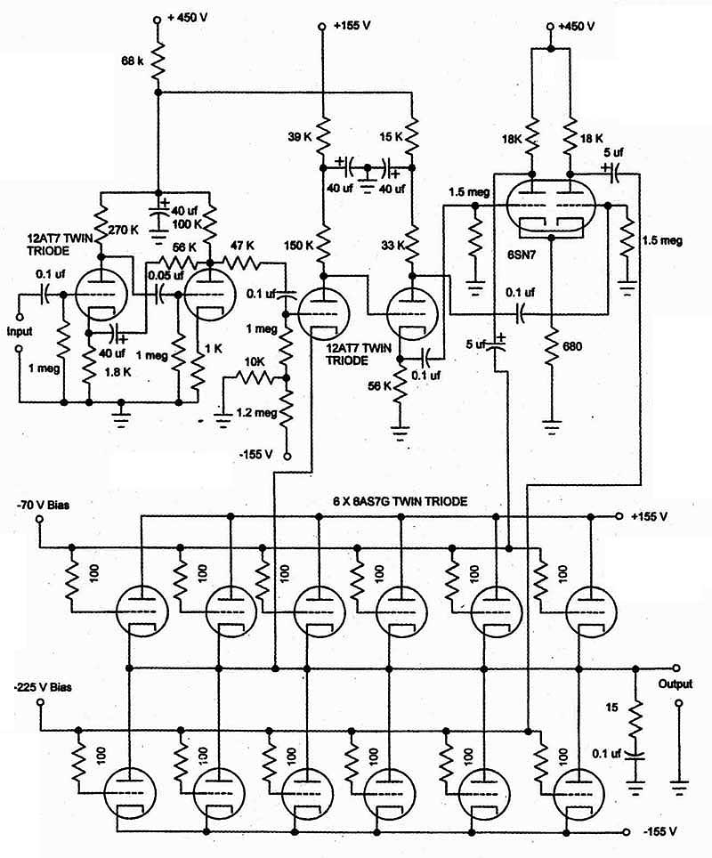
FIG 2: First modification circa 1961
NEW MODIFICATIONS
I have been a subscriber of Audio Amateur and its descendants since the early 1970s. Unfortunately, I never sub scribed to Glass Audio. However, when Audio Electronics and then audioXpress were born, I started reading about tubes again, rekindling my interest in my OTL amplifier. So one day I dusted off the old amp and started experimenting with it. The following is what I came up with (Figs. 4 and 5):
1. I made my first modification because the power transformer for the ±155V supply gave up the ghost (I caused an inadvertent short that may have had something to do with it). When I replaced the power trans former, I decided to make the bias supply for the output tubes independent of the ±155V supply, so I dispensed with the voltage doubler, and added yet another transformer, another rectifier bridge, and filter capacitor.
2. I changed both 12AT7s to 12AX7s, now V1 and V2 in Fig 4. The 12AX7 has an amplification factor of 100, as opposed to 60 for the 12AT7, which translates into more potential voltage gain.
3. I believed that the old power amplifier circuit did not provide adequate drive to the output tubes and that was the main reason the power output was less than I expected. So I changed the method of phase inversion using a cathode-coupled amplifier instead of the original configuration in the first stages of the power amplifier section. This also provided a convenient way to apply feedback from the global negative feedback loop.
Instead of going from the output to the cathode of the first tube in the loop as in the original amplifier, the feedback now goes from the output to the grid of V2b, analogous to modem transistor power amplifier or op-amp topology. I used a constant-current source in place of a cathode resistor in V2 and replaced the 680W cathode resistor with a constant-current source in the V3. The current sources act like a very large resistor, which maximizes the output and increases the linearity of the cathode-coupled amplifiers.
I selected current sources of about 0.3mA for V2 (0.15mA for each section) and rather large plate resistors at 470k. At first I used smaller resistors in the plate circuit, but I developed problems with grid current in the high mu triodes. I used 16mA for V3 (8mA for each section), with the same 18k plate resistors used in the original amplifier. Perhaps getting carried away with current sources, I also replaced the load resistor of V1a with a current source. The current source, again, acts like a very large plate resistor and maximizes the gain of the circuit, which in turn allows an increase in the feedback and thus reduces distortion. I chose a plate current of about 0.15mA for the plate current of V1a. I left V1b in a conventional configuration.

FIG. 3: Power-supply modification circa 1961.
Some purists may say that this is no longer a tube amplifier. I suppose you could argue that. However, all the gain of the amplifier (voltage and current) is de rived from tubes. The transistors that are used for the current sources are actually functioning as resistors. Anyway, after all is said and done, most of the current in the amplifier must run through the PN junctions of the rectifier diodes, and if you replace the 5Y3 with a pair of diodes (which I will probably do if the 5Y3 in the amplifier dies), all of the current will need to pass through silicon diodes.
Surprisingly, I have had very few problems with high-frequency oscillation and no problem with motorboating. The only issue I had with high-frequency stabilization was solved by the placement of a 22pF capacitor, C6, in parallel with the grid resistor on V2a.
One further comment: There is a mis match in the output stage caused by the fact that half of the 6AS7 sections have the load in the plate and half in the cathode. The original circuit in Fig. I tried to compensate for this by using unequal resistors in the phase inverter, which was the second section of the second 12AT7. When I tried to allow for this after my modifications, any method I used decreased the performance of the circuit (asymmetrical clipping and reduced power output), so I finally gave up and let the 100% negative feedback handle the compensation.

FIG. 4: Completed amplifier with cathode-coupled amplifiers and current
sources.
RESULTS
I was very pleased to find that the amplifier clipped at a little more than a whop ping 50W RMS output into 16 almost 40W into 8 ohm and 25W into 4 ohm. The output impedance is around 0.5 ohm. The amplifier is very quiet, producing less than 0.002V RMS of noise at the output with the input shorted to ground. The voltage gain is a little over 17 (almost 25dB) and the amplifier needs 1.6V RMS for full output.
At 4W output, the frequency response is dead flat from 10Hz to 60kHz, and is 1dB down at 100kHz. At 45W it is flat from 10Hz to 25kHz, and is 2dB down at 55kHz; it drops off rapidly to 7.5dB down at 100kHz.
Harmonic distortion is depicted in Fig. 6 and shows an improvement over the original amplifier. Unfortunately, I did not perform distortion tests on my old amplifier before I modified it. (It never occurred to me that I might write this article.) The graph of the old amplifier was reproduced from the graph in the original article.

FIG. 5: Latest power-supply modification.

FIG. 6: Distortion comparison.
The frequency used for the test was not specified in the article, although you could assume it would be in the neighborhood of 1 to 2kHz. The distortion tests I have recorded here for the new amplifier were done at 1500Hz.
CONSTRUCTION
I constructed the original amplifier on two different chassis as was the custom in the early ‘60s. I built the power sup ply on one chassis and the amplifier on the other, with a cable connecting the two. All the wiring is point-to-point, except for the added current sources which I built on two small pieces of perfboard attached to the amplifier chassis in convenient locations.
Having two chassis caused a problem for me from the beginning. If I were starting again from scratch, I would build it all on one. I used an eight-conductor cable that plugged into an octal socket on the power supply. Six of the conductors were used for each of the power supply components: ground, +450V supply, +155V supply, —155V supply, —70V bias, and the —225V bias. This left the 6.3V filament supply.
Unfortunately, I had not adequately allowed for the fact that each of the 6AS7Gs requires 2.5A of filament current. The wire size in the cables was too small and became pretty warm when I first tested the amplifier, so I paralleled more wires and taped them to the cable. There was a second octal socket I originally installed to power a Dynakit preamp I built along with the amplifier. Some early Dynakits did not have their own power supply and tapped into the supply of the power amplifier. Later, when I quit using that preamp, I used that socket to further parallel the filament supply.
Photo 1 shows the completed and modified amplifier. As you can see, it is
strictly utility.
If you wish to build the amplifier, as I mentioned, I suggest you build it on one large chassis. Table 1 is a parts list for the amplifier and power supply. If you have trouble finding the five 700V electrolytic capacitors listed there, you can use two 400V 10uF capacitors in series for each one instead.

FIG. 7: Meter driver circuitry (see text).
ADJUSTING THE OUTPUT BIAS
The best way to adjust the bias when the amplifier is first tested is as follows:
1. Attach a power resistor of 10 to 30 to the output.
2. Remove the 6AS7Gs from the amplifier, then turn the amplifier on.
3. Adjust the bias on the 6AS7s with the output load on the cathode to -70V.
4. Adjust the bias on the 6AS7s with the output load on the plate to -225V.
5. Turn the amplifier off and replace the 6AS7Gs in the sockets.
6. Attach a voltmeter across the output on a scale of about 15V. I like to use an analog voltmeter for this task. Turn the amplifier on and let it warm up for a few minutes.
7. Looking at the meter, move one of the bias potentiometers so that the needle moves toward zero. When you get the needle close to zero, I suggest you wait about 5 minutes. Then change to a 1 or 1.5V scale on the meter and adjust it as close to zero as possible. You should be able to get it within 100mV or so.
8. Leave the amplifier on for a few hours and then readjust it again. Plan on readjusting it from time to time be cause as the tubes age it will tend to drift a bit. After a month or so of use, it drifts very little once it warms up.
I found that it is handy to build a meter permanently onto the chassis for periodically balancing output tube bias. I have included a schematic (Fig. 7) for a driver circuit for an analog meter with a full-scale (FS) current of about 1mA or so. Included in Fig. 7 are formulas for calculating resistor values for the circuit depending on the actual FS current of the meter.
Except as indicated, the resistors and zener diodes are all 1 and the capacitors are ceramic disks. The other diodes can be low-power silicon rectifiers such as 1N4001 series, and the opamp is a 741 or equivalent. You then ad just the bias for the lowest possible reading on the meter.
If anyone has any ideas about how to further improve the amplifier, I’m all ears! This story is probably not over.
REFERENCES
1. O. P. Dickie Jr. and A Macovski. A Transformer less 25 Watt Amplifier for Conventional Loudspeakers Audio Engineering June 1954 Reprinted in Audio Anthology Volume Three 1990 C G McProud Editor pp 10-13 Audio Amateur Press
2. F Langford Smith Editor Radiotron Designers Handbook Fourth Edition 1960 pp 347-348 488, 529-532.
============