|
|
Here are some solutions to the problem of 60Hz hum induced into balanced-line microphone cables.
I used to think I knew a lot about interface design for audio systems. I’ve certainly enjoyed reading articles by experts who agree with my beliefs about grounding, shielding, and balanced lines. But recently I’ve stumbled onto something that throws into doubt everything I’ve learned about audio interfacing.
HUM SOURCES
In the lifelong quest for high fidelity, we always seek more dynamic range, pushing headroom up and noise floor down. And what do we meet near the noise floor but our old nemesis, 60Hz hum. Our environment is filled with 60Hz signals, both electric and magnetic, unless you happen to live off the grid and can power every thing from batteries and solar cells. Most hum and buzz can be addressed with shielding and grounding, but to deal with stray 60Hz magnetic fields from power supplies, fans, and motors, we must use balanced-line cables, right?
Wrong! Try this experiment today while I have your attention. Plug a low- impedance microphone into a preamp using a typical balanced-line mike cable with XLR connectors on both ends. Set gain high enough to hear the noise floor while listening in headphones, and drape the mike cable across a wall outlet adapter, the kind that puts out 9V DC for stomp boxes and accessories. If you aren’t used to listening near the noise floor, please note that there is a danger of unexpected inputs causing very loud outputs. You will now be listening to 60Hz hum plus harmonics, coupled from the outlet adapter’s transformer into the mike cable. But that’s impossible, isn’t it?
Now find a microphone with a single-ended cable, having just one center conductor surrounded by a shield. In my studio I happened to have a tie-tac microphone with a single-ended cable to the battery box, and balanced-line from there to the mixer. I was stunned to find that the balanced-line section easily picked up hum from my little power transformer, while the single-ended section suffered no hum at all! What’s going on here? You can also try this experiment with a musical instrument having a single-ended output connected to a balanced input through a direct interface (DI) box. You’ll find the same thing: the single-ended cable rejects hum, while the balanced-line cable lets hum in.
I don’t mean to pick on wall outlet adapters, but you must admit that they are a common source of stray 60Hz magnetic fields in many small studios and listening rooms. Most of us have at least one outlet strip full of them, stuck in a corner or behind an equipment rack, along with our excess lengths of balanced-line cable that connect everything together. This is a recipe for disaster, unless you can figure out what’s wrong and how to correct it. And why have I been buying XLR cables all these years if they don’t protect me from the sources of hum I’m most likely to encounter? I’ve thought about this a lot, and have concluded that the environment has changed since the days when XLR cables first became popular.
It seems that balanced-line cabling must have originally been meant to eliminate hum pickup due to differing ground potentials between the various parts of an auditorium, recording studio, or broadcast station. And it must have done this job very well, because no one would suggest building such a facility today using single-ended cabling. But I don’t think there were many wall outlet adapters sitting on the floor back then.
The first outlet adapter I ever saw was for an AT&T Princess Phone, but now they are everywhere. So why do balanced-line cables allow hum to enter from this new source?
MAGNETIC INDUCTION
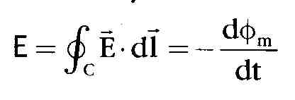
Magnetic fields induce a voltage in a circuit that is proportional to the time rate of change of magnetic flux through the surface area outlined by the circuit. This is known as Faraday’s Law.
Notice that DC magnetic fields—from permanent magnets, for instance—have no effect because their rate of change is zero. Magnetic flux through a surface is defined as the integral over the surface of the magnetic field perpendicular to the surface.

For the simple case of a uniform field passing through a flat surface, the flux is just the product of field times area, with a cosine factor to account for the field’s angle with respect to perpendicular.

You can make a couple of assumptions to simplify this analysis. First, assume that all the induced voltage appears across the preamp input. In other words, the preamp’s input impedance is high compared to the microphone source impedance. Then assume that the 60Hz magnetic field is acting in a relatively small region—say, over 6” of cable or less. This turns out to be important, because it is about the same length scale as the twists in twisted pairs.
TWISTED PAIR CABLE
Now consider the input circuit, including a microphone capsule, the two center conductors in the balanced-line cable, and a preamp input (Fig. 1). You can ignore the braided shield, because it is likely made of copper and has little effect on magnetic fields. The surface area outlined by the circuit is the small gap maintained between the two center conductors by the insulation on each of them. The center conductors are twisted together so that a uniform magnetic field over a length of cable will cross the gap in alternating up and down directions.
Induced voltage will then alternate plus and minus, adding up to approximately zero if the field is the same over a length containing many twists. The reason this fails in this case is that the wall outlet adapter’s external magnetic field is localized to a small region of the cable, perhaps affecting just one twist or so. You could get lucky and find that the cable lies so that induced voltages cancel, but it is more likely that they will add up to be non-zero.
If this model is correct, then induced hum should depend on rotation of the cable, with one positive maximum and one negative maximum per complete rotation. When I rolled the mike cable between my fingers near the wall outlet adapter, this is exactly what I observed (Photo 1). You can get the same effect by sliding the cable length-wise along the outlet adapter. In fact, this is one way to find out how close the twists are in a twisted pair.
I also found that if you unplug the microphone but leave the cable connected to the preamp input, the circuit is bro ken and the hum goes away. If you short pins 2 and 3 at the microphone end, the circuit is complete again and the hum comes back. None of these observations hold, however, for the single-ended mike cable. Rather, it ignores magnetic flux because it doesn’t define a circuit whose enclosed area the flux can penetrate.
FIXING THE PROBLEM
Now that you have a good description of the problem, what can be done to minimize it? Luckily, stray fields from wall outlet adapters are highly localized. If you think of it as a magnetic dipole, the field strength will fall with the third power of distance along the dipole’s axis. So the first step is to keep wall outlet adapters far away from mike cables, preferably up off the floor.

FIGURE 1A: Schematic diagram of a conventional balanced-line mike cable, made
with shielded twisted-pair wiring. The mike cable itself and the XLR connectors
on both ends are antennas for induced hum.

FIGURE 1B: Twisting the inner conductors together limits the gap between them,
where magnetic flux can enter, to the combined thickness of their insulation.
Next, you see that for a given field strength, the flux enclosed is proportional to the area between the conductors. You should be able to reduce induced hum by choosing a cable with smaller conductors having thinner insulation separating them. I happened to have some Belden #8640 instrumentation cable on hand which consists of two strands of 28 gauge magnet wire with enamel insulation, twisted and covered with a foil shield. So I made a mike cable out of it, and measured a 12dB improvement in hum rejection (Table 1) compared to a generic balanced mike cable. Unfortunately, this cable is too fragile for field use, but you could certainly choose more convention al cables that have a reduced insulation thickness on the inner conductors.
At this point it occurred to me that there is a very weak link in the chain—the XLR connectors themselves. Inside both plug and socket, the two center conductors are forced to a separation of about ¼”, over a length of almost 1”. This represents a huge area which is essentially an antenna for hum. I confirmed this by connecting two mike cables in series and placing the junction near a wall outlet adapter.
Sure enough, the XLR connectors picked up a huge hum signal, more than 20dB greater than the cable alone. But don’t the connector shells help us out here? Unfortunately, they are typically made of non-ferrous metal and have no effect on magnetic field. You can work to eliminate inline junctions by having cables long enough for every application, but that still leaves the connectors in patch bays and stage boxes. Until new connector designs come along, you’ll just need to make sure that stray fields don’t encroach on your connectors.

PHOTO 1: Bench setup for measuring induced hum. Note that instruments have
been pulled together for the snapshot, but were farther apart for actual measurements.
This was necessary because each instrument has its own power transformer and
stray magnetic field. Microphone shown was replaced with a shorted plug for
actual measurements.

PHOTO 2: Close-up of computer connectors wired in star-quad configuration.
This connector pair is inserted in the middle of a star-quad mike cable, which
was made by cutting the ends off a shielded MIDI cable and installing XLR connectors.

TABLE 1 Hum induced in microphone cables and connectors, measured at the input
of a Shure FP32 mixer. Two different wall outlet adapters are shown for comparison:
#1 from a big-name manufacturer, #2 an unknown import. All values are relative,
since the details of the magnetic fields are not known. All measurements are
audio band width (20Hz-20kHz), average AC volts, in units of RMS voltage. Microphone
end of each cable was terminated in a short circuit.
MORE SOLUTIONS
You won’t believe what I did next. Based on my experiment with the tie-tac microphone, I made a single-ended mike cable, with some single conductor plus shield coax and XLR connectors on both ends (Fig. 2). The incredible thing is that it worked! Good clean sound and very little hum from wall outlet adapters.
But I can’t recommend this as anything other than a laboratory curiosity. The reason is that you’d be giving up the protection from circulating ground currents that you enjoy with balanced-line cables. Also, phantom power wouldn’t work as intended. Avoid single-ended solutions, for now.
Now isn’t there some way you can have the best of both worlds? Rejection of stray magnetic fields and protection from circulating ground currents in one cable? While researching this article I learned of a cable type I hadn’t heard of before, the “star-quad” configuration. Star-quad is defined by Wikipedia as “a cable with four conductors in a square formation, in which opposite conductors are connected in parallel at both ends to form a single, magnetically-concentric balanced pair, in order to minimize magnetic induction.
I had to try this, so I cut the ends off a 4-conductor shielded MIDI cable and put XLR connectors on each end, carefully connecting opposing conductors in parallel (Fig. 3). For this to work, I believe that all four conductors must be twisted about a common center. Two twisted pairs twisted around each other probably won’t help. I must say that star-quad is the answer.
I measured a 20dB reduction in induced hum as compared to a generic balanced mike cable. Yet, pins 2 and 3 are still isolated from ground, so protection against circulating ground current is maintained and phantom power continues to work normally It’s tempting to throw out all my old mike cables and replace them with star-quad units, but what about the connectors? As long as there is an XLR connector on each end, even the best cable can still be a hum antenna.
In high-resolution applications, it may be desirable to use a non-standard connector, one that maintains a magnetically- concentric balanced pair along its length when connected to star-quad cable. But would the performance improvement justify breaking with the long-standing tradition of XLR connectors?
By now you should know what my next experiment was. I cut my home-made star-quad cable in half and inserted a pair of computer connectors, using five adjacent pins to connect the shield and four separate inner conductors (Photo 2). I wired the connectors so that opposite conductors would maintain their formation as they entered and exited the connectors. My first attempt yielded better than 30dB improvement in hum rejection, compared to a standard XLR connector pair.
CONCLUSION
It seems clear to me that for high-resolution applications, you should replace conventional two-conductor plus shield micro phone cables with four-conductor plus shield cables wired in a star-quad configuration. But it doesn’t make sense to do this until you have a connector that maintains the hum rejection of star-quad cable, while retaining the field-proven robustness and ease of use you’ve come to expect from XLR connectors. Such a connector would need to be available as plugs and sockets, in both cable ends and chassis mount versions. It should be available with RF suppression built-in, not tacked on as an afterthought. And it should be suitable for designing into microphones, with appropriate strain relief for hand-held applications.
Some of you may be old enough to remember a time before XLR connectors were standard on microphones, when every mike included a cable with stripped and tinned ends waiting for you to attach your connector of choice. Such a time may be approaching again. Meanwhile, you can continue to experiment with new configurations, and report your results in journals such as audioXpress or online forums/blogs such as diyaudio.com.
High-end mike preamps would have one more requirement. It now seems likely that to push hum below the noise floor, point-to-point wiring and circuit board traces inside a microphone preamp would also need to maintain a magnetically-concentric balanced pair configuration, at least until reaching the first gain stage. This will be necessary because— whether your gear is rack-mounted or just sitting on a table—it will be part of a system containing a variety of power transformers, each having its own stray magnetic field.
What about switching power supplies, the kind that are used with laptop computers and that don’t have an iron transformer operating at 60Hz? I tried my various test cables draped over an adapter powering the computer I use to type, and heard a raspy buzz at a level similar to iron transformers, with some 60Hz and other components as well. So that’s not the answer either.
One author has designed a rack- mounted power supply for replacing “wall warts,” which could be a good improvement in some applications. Alert readers will notice that I haven’t mentioned triaxial cable, which has one center conductor and two concentric shields, all of which are electrically isolated. I guess I just didn’t get around to it. If any of you have tried using triax in audio applications, I’d love to hear about it.

FIGURE 2: Single-ended mike cable, made with single conductor plus shield
wiring. This laboratory curiosity has surprisingly low induced hum, but cannot
be recommended for real-world applications.

FIGURE 3A: Star-quad mike cable made with four conductors twisted about a
common center, then covered with an overall shield. This cable has very low
induced hum and is well suited for general applications, but see text for discussion
of why you shouldn’t use it with XLR connectors.

FIGURE 3B: Four inner conductors are twisted about a common center to provide
a magnetically concentric balanced pair. Opposite conductors are connected
in parallel at both ends, so red and black are one side of the balanced line,
while blue and yellow are the other side.
REFERENCES
1. Gary Gab, “Grounding and System Interfacing,” Jan. ‘07 audioXpress , pp.26-33.
2. Bill Whitlock, Answers to Common Questions About Audio Transformers, Jensen Transformers, Inc. Application Note AN-002, 1995, available online at www.jensentransformers.comlapps_wp.html.
3. Paul Tipler, Physics for Scientists and Engineers, 4 ed., W.H. Freeman and Company, New York, 1999.
4. See Wikipedia, XLR connector, http://en.wikipedia.org/wiki/XLR_connector.
5. Ron Tipton, “A Multiple “Wail-Wart” Power Supply, ”June 2008 audioXpress .