This approach to cleaning power lines employs a filter circuit.
In part 1, I reviewed why you may need to clean up your power lines and looked at a simple voltage booster. In this article I begin to explore more ways to clean the noise.
I prefer to use a separate circuit for a line-cleaning filter. The equipment that does best with a filter does not always need the extra voltage. Two boxes allow me to use them both to best advantage.
The simplest filter can be a resonant circuit, which is formed by placing a capacitor across an inductor. The current travels from the capacitor into the inductor and back again. This is called a circulating current.
If the capacitor and resistor were perfect, this flow would never stop. That means that if you just fed this from an AC current source, the voltage would continue to rise until something blew up. Of course, I am connecting it to a fairly stiff voltage source, so I am trying to approximate the immovable object meets the immutable force, and hope I win.
You know that when inductive and capacitive impedances are equal, they are resonant. I chose to use a 72mH inductor, which gives me an impedance at 60Hz of (2*pi*PL), or 27.14Q. This will limit the current drawn from a 120V 60Hz AC line to 4.42A. A capacitor with an impedance of 27.14Q at 60Hz would be (1/2*pi*z*F), or 97.7RF.
Even though both the inductor and capacitor draw current, they only dissipate a small amount of power. Perfect components would dissipate none! The energy stored in the inductor would be ½ * L * i or 0.7 joules per peak, which should be enough to make up an 84W shortage!
PARTS SELECTION
The problem with this approach is the hidden components. To a small extent, the capacitance of the wiring in the AC supply will add to the designed storage capacitor. Much more important, the inductance of the power transformers in the audio equipment will have their inherent inductance placed in parallel with the storage inductor, effectively reducing its value. I will need to add capacitance to correct for this.
To accommodate these unpredictable variables, I made the resonant capacitor adjustable ( Fig. 1). In addition, I included a current monitor. The resonant capacitor is made up of many smaller units. These capacitors are basically bi nary weighted to minimize the number required.
I picked commonly available motor-run-type capacitors in a sealed metal can.
These are available from most industrial suppliers. The capacitors in Fig. 1 are from my semi-local supplier; Grainger or your local motor shop will also have these. Check to see whether the mounting strap is included or is extra. Because the current in these capacitors will be many amps, don’t try to use ordinary metalized film capacitors. The voltage here is at least 370V peak-to-peak under good conditions; skimping on these parts is not only a bad idea but is a safety issue.
The inductors presented a bigger problem. I could not find an inductor rated for this kind of service. Not only is the voltage breakdown an issue, but so is the resistance of the windings. As the current keeps going round and round, whatever resistance just dissipates energy, making the coils become warm. In addition, because these are iron-core coils, there is a current limit at which the inductance drops.

Above: Fig. 1: Resonant circuit. Part numbers Digi-Key, except inductors
Parts Express, and capacitors typical McMaster Carr.
If you ever built a telegraph Out of a coil wound on a nail and a piece of tin can as a child, you probably wondered if adding more turns to the coil made it work better. If you added lots and lots of turns, you were probably surprised to find out that after about 20 turns of wire on the nail, your electromagnet did not become stronger. That is because once you have magnetized the iron all the way, there is no more to magnetize. This limit occurs in all transformers and inductors. The higher the current, the less time it takes for the magnetic core to saturate. All the extra energy is available to become heat.
I am using Jantzen inductors from Parts Express rated at 700W, but no frequency for this power level is given. That is why I used four coils in series. It gives more power handling and a higher inductance, which lowers the circulating current and voltage across each coil. Note that these inductors are not designed for this service. The insulation is not rated for this use. You must be sure they are insulated from each other and from ground so that each coil effectively sees only 30V. The coils will hum because they are not fused or varnish impregnated coils.
To reduce the noise and make mounting them easier, I encapsulated my inductors by filling medium-size disposable plastic food containers from the grocery store with half of a cartridge of silicone window and door seal caulk. Wearing latex gloves, I then pressed the coils into the goo and smoothed out the tops. A bit of round scrap plastic pressed into the center made my mounting hole. The silicone rubber compound took a few weeks to set enough for use.
There is also an important issue with iron-core inductors: The magnetization versus current curve is not linear. That means that depending on the current, the inductance will change. Four inductors in series means more iron, less current and so less swing. You could, of course, use a larger inductor if you can find one for this use; be sure to reduce the capacitor appropriately.
CIRCUIT OPERATION
This circuit really needs to resonate smoothly at 60Hz. It will pull current from the line to do this. When the voltage sags at the top of the cycle, this circuit will then push current back into the line raising the voltage. The capacitor also acts as a low-pass filter for noise on the AC line.
One downside of the resonator is that the energy it puts back goes both to the outlet where your equipment is connected and back into the wall outlet to try and fix the rest of power service. This problem is reduced by the inductance of the filter, the resistance, and the inductance of the building wiring. These hidden components here work to your advantage.
Taking in energy and putting it back out each and every cycle is work. The internal resistance of the inductor and the dissipation of the capacitor cause some of the work energy to become heat. The capacitors I chose have a very low dissipation factor (.005) at 60Hz, and the inductors have low DC resistance (0.17412). These parts barely become warm in my version. If you get the wrong parts or try for too much energy storage, this circuit can become quite hot!
If you try this filter circuit, you will note that there is some buzz from the inductors, which gives a nice sense that there is lots of energy here. The capacitors should come with a note that the oil inside is flammable. That strongly suggests using a quality metal case and mounting the inductors with nonflammable materials. Also, don’t use a piece of bare wire as a tie wrap to hold the coils in place. That would make the coil a shorted transformer!
There is a great place to put a cleanup resonator such as this: after the loosely coupled power transformer inside of your preamplifier or source. Keep in mind you must size the power transformer for the extra circulating current this will add. Very few transformers specify their inductances. You could measure it with a bridge, but the more accurate method is to use a capacitor box to determine the best value based upon the current draw of the input to the transformer. The voltage rating of the winding used and the final capacitance determine the power storage. As far as I know, no one does this commercially.
You will probably choose to try this kind of filter on the power line that feeds your preamp, CD player, and tuner. Its back into the wall action will also help your other gear. I find that this circuit noticeably mellows my CD player’s sound.
CONSTRUCTION
To build either power line cleaner, you will need a metal box. A great source is your local electrical supply house. Boxes are typically stocked from 6” x 6” x 4” to several square feet and come painted or galvanized; you should purchase a painted one. In addition to the box, the store will also have a suitable strain relief (called a straight liquid tight cord relief for a ½” knockout for the size of power cord you are using), the nut to hold the grip (sold separately), and even the outlets for this project. Be sure to pick up a box of yellow or even red wire nuts (the real ones—not the home center cheapies) — they might just come in handy. I would also buy a round 14 gauge 8’ extension cord for the inlet cord and use some of the extra for the internal wire. They also will carry THHN wire if you need more.
The boxes from electric supply houses come without any holes in them, so you must drill or punch your own holes. Be sure to also pick up outlets that mount in round holes! These are sometimes called clock outlets. The long name is a NEMA 5-15 straight blade single female receptacle.
The box will have at least a front that comes off and can be drilled and punched while completely flat. If you design your power supply correctly, you can drill all the holes you need with either regular twist drill bits or a stepped Unibit (also available at your supply house). The hole for your cord grip should be 5/8” and made by drilling a 3/8” hole and a 5/8” chassis punch (the supply house carries this as a ½” knock out punch), or you can use a Unibit.
Place all your components on the plate, leaving room around the capacitors and inductors for ventilation. Once you know where you want the holes, mark the locations with a pencil or marker. Then use a center punch to make a dent for the drill bit before you try to drill any holes. Gloves are a great way to keep blood off your project while drilling. Safety glasses will let you ad mire your work later.
Pushing down hard with a big drill leaves the scars that show how macho you are. Go slowly and smoothly if you prefer clean work. Of course, a hand drill is fine for this, but a drill press is better if you can set it to the right speeds. 1500 surface inches per minute (not RPMs) is a good speed for steel. RPM = 475/drill diameter. Whenever drilling metal, a drop of oil before you drill should be a suitable offering to Vulcan to ensure a clean hole.
The AC outlet(s) require three holes with a 5/32” diameter. These should be in a line and spaced 1.640” apart (or 1 41/64” for those with 6” steel rules and adjustable dividers!). Enlarge the center hole to 3/8”, then use a 1 3/8” (or 35mm) chassis punch. This (Mouser 380-0350) will give you a hole big enough for the outlet. If you make a mess, just get a wall plate for your out let and use it to enhance your skillful design.
Before you use a chassis punch (even brand new), you should always hone it. The chassis punch usually has three parts: the punch, the die, and the draw bolt. To sharpen the punch, first take everything apart. Put a piece of 400—grit silicone carbide waterproof sandpaper on a flat surface. I don’t use water or oil. Then push the flat surface of the punch away from your body as you wipe it flat on the paper. After three strokes, turn it halfway and do the other side. Some folks prefer a figure-eight grinding pattern. Wipe off any grit and then put single weight oil (5 wt) on both the punch and the draw bolt. You probably cannot find single weight oil, so use Mobil One. Don’t use universal oil such as 3 in 1 or multi-weight automotive oil. The thickeners they contain tick off Vulcan.
If you don’t want to use chassis punches, you can use a nibbler—or even use a hole saw—to make the larger holes. There are two kinds of hole saws. The good ones have a drill bit in an arbor that holds the blade. The other kind has an adjustable blade and is referred to as a suicide cutter for good reason. Most hole saws are good for wood or metal if you use a lubricant. Be sure to screw your flat sharp metal plate to a large piece of wood before you attempt to cut the larger holes. Use four screws in the plate mounting holes.
Once you have finished your metal work, you should paint the case over the gray primer paint. One area of concern is where the preassembled filter mounts to the plate. The screw holes and area under the filter should be reasonably bare metal. Sand or scrape this area and then apply masking tape before you paint. You can leave the tape on until you are ready to begin wiring.
Hardware-store or home-center paints are fine. Auto-parts stores carry better paints. I use a fully ventilated spray booth that has an “explosion proof” exhaust fan and a cold LED light source. You should paint outdoors on a calm day and leave the chassis outside for an hour or two. Second choice is a garage with the door open.
ASSEMBLY
Allow at least a day or two for drying. Then you can mount all the parts. I find 6-32 pan head Phillips machine screws are great for this. I use nuts with built- in lock-washers. Many of the parts will take fast-on connectors. I prefer to solder to all of the parts except the outlets, which will take a wire directly.
This project is great for a soldering gun! If you don have one, use a large electric soldering iron; 25W is not going to be enough. The best place to begin to wire is with the power cord and then along to the output. You should wire the fuse holder so that the incoming line goes to the terminal at the back. The side terminal goes to the switch. remember the notch in the switch’s barrel is the “off” side. To mount the switches, use a wrench on the inside of the case for a flush-looking front panel without scratches.
Don’t solder to the fuse holder when the fuse is in it! You can mount the MOVs on the filter’s terminals so that you don’t need terminal strips. The black AC hot wire goes to the brass terminal on the outlet(s). The white goes to the silver, and the green is ground. If you did not get mounting straps with your capacitors, you can fake them with a strip of old tin can. When you are finished, remember to install the fuse.
These gizmos mounted in steel boxes with high magnetic fields will want to hum. If the case is not tight, the hum will become a buzz. You can use a bit of silicone rubber to form gaskets where this happens. Rubber feet will prevent this song from spreading to other gear.
See the boost transformer circuit in Photo 1.
TESTING
Before you plug your project in, be sure to check for shorts across the line with an ohmmeter. If you correctly assembled the resonant filter, you may think you have a dead short across the AC line because the DC resistance of the inductors is so low. I measured l.1Q! It’s even more important to check for shorts to ground. I then plug everything in through my light-bulb box. I may see current drawn even without a load! That is because the output filter is trying to fix the incoming line! To adjust the resonant filter circuit, turn on only the 60W lamp ( Fig. 2).
Plug in the filter without anything connected to it. I found that setting the switches to a value of 93jiF caused the lamp to be at its dimmest. Adjust the capacitor bank switches when the power is off. Otherwise the extremely high circulating current will weld the switches closed. There are three reasons for the difference between the value I would have expected (97.7) and what worked: One, the value of the capacitors is slightly off; two, the inductors are not quite on value either due to manufacturing or mounting; three, there is extra capacitance elsewhere that is coupling into the circuit. I, of course, used my bridge to check the capacitors arid my un-mounted inductors. They both were well within tolerance.

PHOTO 1: Boost transformer circuit.

PHOTO 2: The resonant filter circuit.
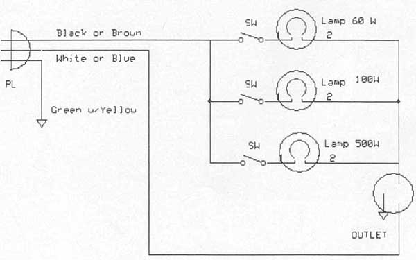
Above: Fig. 2: Light bulb test box.
After you first trim the capacitors, connect the equipment that you wish to serve. You may need to readjust the capacitor value (Power off while adjusting!). If you own a clamp-around ammeter, use it for adjusting the resonant capacitor bank. For those who don’t own one, I have included a current transformer to make this easy. Just connect an AC. voltmeter to the output and trim for the lowest reading. I got my minimum reading down to about 220mV. Hooked up to my audio gear, the required capacitance was about 120uF (Photo 2).
Now check that the output is the right voltage, which is harder than it seems. Your equipment may have been designed when the wall outlet was expected to be 110V, 117V, or even 120V. I design for a low line voltage of 108 and a high line voltage of 132V. The AC voltage from either circuit is now “stiffer” than an ordinary outlet; this will increase the turn-on surge. If your equipment was borderline, it may burn out the silicon rectifiers.
If your gear is classic, I would aim for 117 to 120 PRRI volts. If the voltage is higher, you may wish to put a thermistor inrush current limiter (Digi-Key 490-3942 to 490-3948) in series with the AC line going into your particular piece of equipment. With modern gear, I would be comfortable with line voltages of 126V or so. If you have saved and read the manuals, they may tell you that 130V is fine. Keeping a PRRI volt meter here for the first few uses is a good idea.
These devices don’t correct for changes in the incoming line voltage. If you built the filter version, this will act as a very stiff load and help flicker type of line bounces, but not brownouts. There are devices that use tapped transformers and switches to automatically adjust the output voltage even if the input voltage changes (brownouts!). I have not added this feature; you might want to try it.
To get the best out of either line cleaner, I would start off with only the preamplifier and music sources fed from a cleaned AC source. Then try just the power amplifier(s), and finally every thing. Leave it set up whichever way you prefer.
There are several interesting variations in these basic designs. One is a transformer that actually lets the magnetic core go into saturation. A capacitor can then resonate with the inductance of the transformer to re-circulate this excess energy. As the core saturates, the output waveform won’t be a sine wave but will have constant peak-to-peak amplitude even as the input voltage drops. This design yields what is called a constant voltage transformer.
There is another method to clean up the AC line that does not use circulating currents or dissipate as much heat. I will examine that and other methods in Part 3.