|
|
Add versatility to your playback of those vintage vinyl records!
At the risk of being laughed off, I nonetheless feel compelled to confess that, until relatively recently, the turntable I used for listening to treasured vinyl was a 1960s-vintage rim-drive broadcast transcription turntable. This perverse choice was prompted in part by nostalgia from bygone radio station experience, as well as a refusal to accept anything less than a 10-lb platter driven by a washing-machine motor as an adequate means of spinning a record.
But after watching woofer cones undulate at their near-maximum excursion during violin solos, and supposing that a good deal of Doppler distortion was being generated and amplifier power wasted, I finally retired the “Rumble-Master Pro” and replaced it with one of those direct-drive turntables favored by dance club DJs. What a nice surprise to find that the new turntable not only runs circles around the old one in terms of noise and startup time, but its integral tonearm appears to be well made and nicely balanced. What’s more, the ability to “scratch” could help open doors to new employment opportunities in these troubled economic times.
BACKGROUND
Buyers’ guides in old hi-fi magazines used to list audiophile-grade turntables that ranged from ultra lightweight stamped-sheet metal designs to heavy lathe-turned platters, most of them rim-driven by an AC motor through a rubber-tire idler wheel. These seemed adequate for monaural recordings, but suffered to a greater or lesser extent from motor vibration and other mechanical noise in the vertical plane. This effectively signed their death warrant when stereo records came onto the scene in the late 1950s. Subsequent generations of turntables targeted the specific playback needs of stereo records and employed belt-drive and direct-drive technologies with quiet, servo-controlled DC motors.
It was the British genius Alan Blumlein who invented the “45/45” stereo disc recording system in 1931 (see The Inventor of Stereo: The Land Works of Alan Dower Blumlein). Stereo records did not achieve commercial success, however, until the Westrex company in the US refined the “StereoDisk” process and brought it into the mainstream in 1958.
The left and right channels of a stereo record are recorded at a 45° angle on opposing groove walls, but an analysis of the recording process generally considers the vector sum and difference of the two channels. The L+R stereo sum represents the lateral (side-to-side) component of groove modulation. Monaural “LP” records had always been lateral recordings, as were almost all the 78s that came before them. This meant that stereo records were “backward compatible” with mono players, and the older monaural records could be played just fine on stereo systems.
The L-R “stereo difference” information is the vertical “hill-and-dale” modulation component of the record groove. Typical stereo music has far less energy in the L-R domain, so distortion mechanisms fundamental to the vertical province of the recording process are of less concern in a stereo disc recording. Furthermore, it has long been standard practice in stereo disc mastering to blend low frequencies to monaural, thus saving the cutterhead and playback cartridge from having to undergo high-amplitude vertical excursions.
Nevertheless, good stereo phono cartridges have high compliance (their ability to follow the groove) in all planes, so even though the lower music frequencies are purposely restricted to lateral groove modulation, the playback system remains sensitive to vertical turntable rumble. Ironically, this situation may actually be less of a problem today with the popular trend toward the use of subwoofers, which respond to the L+R stereo sum common to both channels, fundamentally ignoring stereo-difference (L-R) low frequencies.
HOW THIS PROJECT STARTED
My old broadcast turntable was wired to a 1950s-vintage phono preamp that had a pair of very useful front-panel switches. One switch summed the left and right channels to mono, giving a substantial reduction in turntable rumble for mono records and making certain surface noises and distortion less audible with old 78s and early LPs. The other switch inverted the phase in one channel. With both switches engaged, the system played vertically modulated “hill-and-dale” records, such as Edison Diamond Discs, Pathe 78s, and some 1940s-vintage broadcast transcriptions.
My new direct-drive turntable has an extremely quiet built-in preamplifier, but I really missed the versatility of playback mode selection. This prompted a look into just what it would take to restore features of the old preamp and maybe even add another one or two.
THE “GROOVE JOCKEY”
The project evolved into a line-level, unity-gain signal-conditioning module (Photo 1) that goes between the output of any phono preamp and the input of the listening system. Construction is a simple panel and circuit board “sandwich” (Photo 2). The device allows you to choose among six playback modes:
1) Normal stereo playback
2) A second stereo playback mode in which low frequencies are matrixed into monaural
3) Monaural “lateral” playback with left and right channels summed
4) Monaural “vertical” playback using the L-R difference signal
5) Playback of the right channel through both speakers
6) Playback of the left channel through both speakers
These modes are explained in more detail with the aid of Fig. 1. Incidentally, the seemingly random assignment of component reference designations on the schematic actually reflects their location on the printed circuit board, in a logical top-to-bottom, left-to-right sequence (Photo 3).
STEREO I (NORMAL)
The left- and right-channel inputs are fed to buffer stages IC1A and 1C1B, which also are configured as second- order high-pass filters. A good deal of turntable rumble is subsonic, better observed as woofer movement than heard as a rumbling noise. These buffer stages impart a low-end rolloff starting at 30Hz. The response of this “rumble filter” is graphed in Fig. 2. 20Hz is attenuated by only about 1dB, but 10Hz is down 10dB, and 5Hz more than 20dB.
The gain of these buffer stages is actually just a bit over unity and you can ad just it using the channel balance control, R2. You can reach this trimpot with a small screwdriver through a hole in the front panel to equalize levels between the two channels. In this first switch position the left and right channels are delivered directly to the output jacks.
STEREO II (MONO BELOW 200Hz)
This playback mode gives the greatest attenuation of turntable rumble and can also greatly reduce the large vertical signal component that’s encountered when playing badly warped records. Old 78s often have a nasty “once-around” bump, but heat-distorted LPs can assume the appearance of corrugated-metal roofing. As long as the player can still track the disc, this playback mode will greatly reduce low-frequency offsets caused by warped records.
 FIGURE 1: Groove Jockey schematic.

PHOTO 1: The Groove Jockey as seen from the front.
The two sections of 1C2 are configured as a “matrixing” amplifier. IC2A sums the left and right channels to L+R mono, and IC2B derives an L-R “stereo-difference” signal. The gain of these stages is -6dB to maintain the sum and difference at the same level as either stereo channel.
The four instances of connecting two 10k resistors in series to make 20k resistors may seem odd, but as all 10k resistors in the matrixing networks should have a 1% tolerance, doubling-up on the one value just makes the parts procurement process a bit easier. All other resistor values may be the more common 5% carbon-film type.
The L-R stereo-difference signal (the vertical component of disc playback) is fed to low-pass filter stage IC3B. Starting at about 200Hz, low frequencies are rolled off at a rate of 12dB-per-octave. Again, properly mastered stereo records should have very little vertical component energy at low frequencies to begin with. Following the filter, the L+R and L-R components are de-matrixed back to discrete left- and right-channel signals by IC4, and then sent to the output jacks.
Figure 3 shows the effect of this filter for both lateral and vertical modulation with test signals applied to the input jacks. The two curves represent either a left- or a right-channel output when the inputs are driven in-phase (lateral) and out-of-phase (vertical). For left-only or right-only music components under the filter’s influence, the left and right outputs will be complementary; that is, the two channels will add as acoustical energy in an ideal (anechoic) listening environment to give flat overall single- channel response. In a typical listening situation this means that the directionality of the sound source will be somewhat nebulous from 200Hz downward, but this is pretty much the case anyway, and of course there shouldn’t be a lot of single-channel, low-frequency energy from the record to begin with.
MONO - LATERAL (L+R)
This third switch position is useful for playing monaural records with a stereo cartridge. Vertical rumble and certain types of disc surface noise are substantially reduced by summing the left and right channels. Also, the pops and clicks from mono discs sound less annoying when they come from the same virtual- center position as the mono music, rather than bouncing between left and right as the stylus encounters dirt and scratches on one groove wall or the other.
In the mono-lateral playback mode, the L+R summing stage—IC2A—feeds both outputs. But because IC2A is it self an inverting amplifier, another phase inverter—IC3A—is included in the signal path to keep the absolute phase of the monaural signal consistent with the stereo playback mode.
MONO - VERTICAL (L-R)
Collectors of old records may own some early “hill-and-dale” recordings; these in- dude Edison, Pathe, and a few other labels from the very early days of the phonograph. The World library of broadcast transcription pressings also employed vertical modulation. The Groove Jockey plays these nicely in this mode, because a stereo cartridge responds equally in both the vertical and lateral axes.
Keep in mind, however, that these old records have wider grooves than LPs. Your fragile hyper-elliptical stylus is not going to fit the groove properly and may be sheared off by a piece of grit whizzing along at 78 rpm groove velocities. Stanton, Shure, and some aftermarket stylus manufacturers can supply the proper wide-groove playback stylus for select stereo cartridges.
Listening to a contemporary stereo recording in the L-R playback mode is both interesting and useful. You can immediately hear that there is actually very little energy in that component of a stereo signal (L-R) that actually makes it stereo. All lateral (mono) modulation is effectively cancelled in this mode, and what you will hear is lots of reverb in pop music and very little of anything below 200Hz. The quite audible distortion that you will be surprised to hear in the L-R “difference” signal will make you wonder how the record can sound as good as it does in stereo!
The best way to set the channel balance control, R2, is by listening to a monaural record in the L-R playback mode. Simply tweak R2 for minimum audio out of the speakers. You can also make this adjustment with a stereo pop- music record. Just turn R2 until the lead vocalist, almost always panned to the center position, disappears from the mix.

FIGURE 2: Input stage high-pass response.

FIGURE 3: Stereo matrix mode response.
You can also fine-tune tonearm lateral bias, the “anti-skating” adjustment, when listening in the L-R mode. Audible distortion will drop to its minimum when the stylus bears equally on both groove walls.
The vertical mode routes the output of IC2B, the L-R difference stage, to both the left and the right output jacks. The perceptive reader will be quick to note that IC2B actually provides R-L at the outputs, and that another inverting stage, such as IC3A, would be required to correct this labeling error. But another stage wasn’t handy, nor was an extra switch section to utilize IC3A for this purpose. This oversight doesn’t compromise the ability to listen to old Edison records, however.
RIGHT ONLY AND LEFT ONLY
You can route a single stereo channel— either the left or the right—to both outputs in these two playback modes. This may not seem a terribly useful feature, but it does come in handy for some listening tests and also allows optimum use of a monaural cartridge.
Despite the utility for playing monaural records that the Groove Jockey provides in the mono-lateral (L+R) mode, some record collectors believe that mono records are best played with a monaural cartridge. Indeed, the high compliance of most stereo cartridges, especially in the vertical plane, seems inconsistent with the groove of an old 78 hurtling past at 3 or 4’ per second. Any warp in the record can send the stylus to the limits of its travel. I have found that an old General Electric VR-II cartridge from the 50s frequently does a better job of playing 78s than my Stanton 681-EEE with a 3-mil stylus.
Simply wiring a mono cartridge to both inputs of the phono preamp would double-terminate the cartridge in two 47k load resistors, the common input characteristic for most phono preamps. Instead, simply connect the mono cartridge to one input—the left, for instance—and set the Groove Jockey switch to left-only to get music from both speakers.
CONSTRUCTION NOTES
The Groove Jockey can use “jellybean” (garden-variety) opamp integrated circuits, but installing these in sockets allows you to substitute any of the many different types available with this common dual-amp pinout. The power supply is bipolar ±10V, giving more than 20dB headroom for the nominal -10dBu output level from most phono preamps. The TL072 chips specified in the parts list draw very little quiescent current from the supplies, but other types may have a higher idling current. If the power supply voltage measures below ±10V, additional current is required, so install the optional 470 ohm resistor, R41, on the board.

PHOTO 2: Rear view of the circuit assembly “sandwich.” Note that the connectors
are mounted on the back of the circuit board.

PHOTO 3: Circuit board and front panel prior to final assembly.
The Groove Jockey is powered by a 24V “wall wart” AC adapter. The bipolar voltage for the op amps is derived from a couple of 10V zener diodes in an “artificial ground” configuration. Op amp ICs exhibit very good rejection of power supply ripple, so additional regulation and filtering is overkill for this simple device.
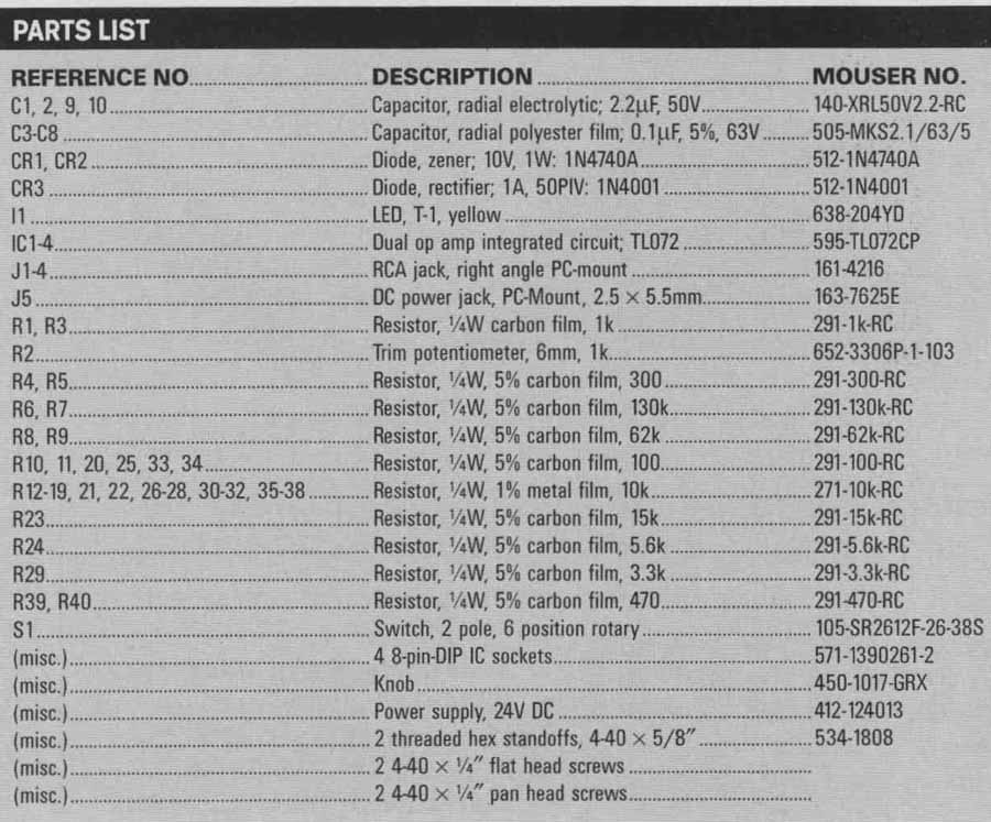
All components specified in the parts list are relatively inexpensive and include their corresponding Mouser Electronics ordering codes.
Photos 2 and 3 show how I mounted the finished circuit board on the front panel, which I cut from a piece of 1/8” Masonite. A panel drilling template has markings for all the holes, plus the black border line that defines the panel dimensions. You can inkjet-print this template onto plain paper and then stick it to the Masonite with 3M “77” spray adhesive. Drill the six 1/8” holes and the one 3/8” hole through the paper template, and sand the panel to the outer boundary of the black border line.
You can easily remove the template from the panel by brushing it with paint thinner and lifting it off. Then you can countersink the two holes for the threaded standoffs from the front, and install two 4-40 x 5/8” standoffs on the rear of the panel with flathead screws (Photo 3). I didn’t have 5/8” standoffs, so I used a combination of ¾” and 3/8”.

PHOTO 4: The Groove Jockey installed in the author’s turntable console cabinet.
Print the panel artwork overlay on good-quality paper; I used a fine letter paper that resembles parchment. When the ink is dry, it’s a good idea to cover the paper overlay with laminating film or clear Con-Tact brand shelf paper before finally sticking it down with the 3M spray adhesive and trimming around the edge with a razor blade. You can easily open up the holes with an X-Acto knife.
Screw the assembled circuit board (with the RCA and power connectors on the back of the board) to the panel standoffs and further secure it with the rotary switch bushing. The switch is just the right height with the supplied lock washer, but you must break off the plastic locating pin so that it doesn’t bear against the back of the panel. Be careful not to change the position of the, switch stop mechanism! The 3/8” switch nut secures it to the panel.
The Groove Jockey circuit assembly slips into a cutout just a bit larger than the 2¾” x 5¾” circuit board. I mounted mine with #4 woodscrews in the turn table console cabinet (Photo 4).
You can download a PDF file containing the drilling template, panel artwork, and circuit board layouts at:
www.inovon.com/jim/groove.pdf.
Simply print the panel art with a laser or inkjet printer. You can also print and photograph the circuit board artwork, or take it to a film-output shop where a true film negative can be produced directly from the PDF.
PARTS LIST:
= = = =