Exploring the 6T9 Compactron in push—pull, with the addition of zener diode bias.
For many years as a youngster I was fascinated with the glow of tubes in electronic equipment. This preoccupation led me to a lifelong hobby of repairing antique radios, TVs, and home brewing tube-based projects. With the rising cost of standard audio tubes, I thought there must be an inexpensive, overlooked tube that would give good audio results. After digging through my tube manuals, I found the 6T9, which is rated at 12W maximum with 250 plate volts into a 5k-ohm load.
I had seen this tube in TVs of the 60s and early 70s as a Class “A” audio amp, but never gave it much thought until recently. Then a light came on in my head. Why not design a circuit using this tube in push-pull? I had never seen this done with this tube. It seemed to be a good candidate because it has a triode and pentode in the same bottle. At $3 to $4 each, it warranted an experiment.
After I breadboarded a circuit scratched out on a piece of paper, it came alive and I was listening to music from this crude setup. The next step was to put it on a chassis that I could use for further experimenting. I used parts and materials I had in my garage workshop, except for the power transformer and tubes that I purchased from Radio Daze.
The chassis is an aluminum panel salvaged from an old computer UPS system that I drilled out to accommodate the necessary parts. I came up with a nice little amp that was easy to build and did not require a shop full of elaborate tools (Photo 1). A hand drill, bits, whole saw, file, and soldering iron were all that was needed along with a rule and center punch to lay it out. You will also need your standard wire cutters, pliers, miscellaneous drivers, and so on.
ABOUT THE CIRCUIT
There’s nothing new about this limiting Class “A” push-pull output circuit except for the way I derived the -8V bias at 250 plate volts as specified in the manual for the pentodes. Most self-biased circuits use a resistor at the cathode to provide the necessary bias on the grids. My thought was to use 5.2V zener diodes (D4 and D5) to provide bias and DC ground without the degenerative effects of AC across the resistor. It also eliminates the need for the cathode bypass capacitor. The best of both worlds, it seems (Fig. 1).
The input is a typical triode Schmitt phase inverter with negative feedback derived from the secondary of the output transformer (T3). I chose this circuit because it uses both triodes (V1A and V2A) without the need for another tube for a voltage amp in the input, keeping circuit design and parts count low.
The power supply presented a small problem. I didn’t have a transformer that would supply the necessary plate and filament currents from the same unit. This led me to use two transformers: one for the plate supply (T1) and one for the filaments (T2). Not what I had in mind, but this was the best I could do.
The cost of the filament transformer is minimal, but required extra space on the chassis for mounting.
The circuitry of the power supply is simple. It consists of a full-wave rectifier (D1 and D2), capacitor (CS), choke (L1), and capacitors (C6). I also used a thermistor (R13: 220-ohm cold, 20-ohm hot) in series between the rectifiers and capacitor to limit the inrush current when powering up the amp. The negative temperature coefficient of the thermistor, when warm, gives me a plate voltage of 255V.
Power for the pentode screens (V1B and V2B) is taken from the second filter capacitor (C6) in series with the choke (L1) from the first filter capacitor (C5). The grid resistors (R8 and R9) are twice the values of the plate load resistors (R6 and R7) of the phase splitter. This helps to reduce the load on the phase splitter.

PHOTO 1: Completed chassis with plug-ins.
Power for the phase splitter may seem a bit unusual. I used a rectifier (D3) and capacitor (C7) for each channel to de couple the power supply from the input. Because a rectifier is a one-way valve electrically, I thought this would be a good way to isolate the input from the power supply, thus causing undesirable oscillation. This arrangement seems to work because the amp did not oscillate or motorboat.
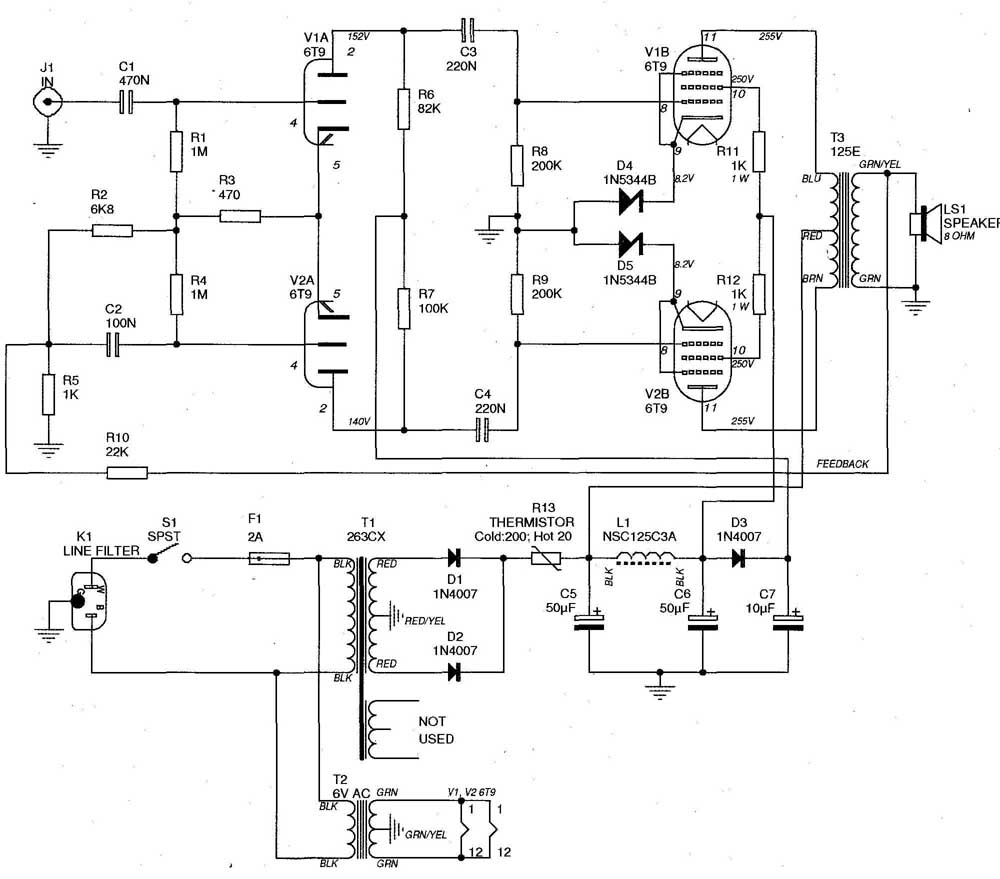
FIGURE 1: Push-pull tube amp circuit.
I used NOS output transformers (T3) that I acquired a few years ago although a Hammond 125E should work nicely.
If the amp oscillates on initial power up, reverse the primary leads of the output transformer (or both in stereo). This should solve any oscillation problems.
CONSTRUCTION
Start by gathering the necessary parts (Table 1), a chassis of your choice, and physically lay the parts out to fit. Drill all the holes and mount the tube sockets, terminal strips RCA plugs, and speaker jacks. Wire the grounds and tube filaments. Twist all transformer and filament leads to help reduce hum.
Be sure to ground the tubes internal shield, pin 6. Continue on with the zener diodes (watch polarity!), resistors, and capacitors. Mount the line filter, fuse socket, filter capacitor, choke, and power transformers and wire in the rectifiers (again, watch the polarity!). You could use a tube rectifier (say, 5Y3 or a beefier 5U4) snake the necessary connections, and eliminate the thermistor if you choose.
I tied the 5V filament leads off to the side because I used solid-state rectifiers. I didn’t try the tube rectifier circuit, so the choice is yours. Now make all other necessary connections and check your work very carefully! For the final step, install the fuse and connect the line cord (Photo 2).
At last, the moment you have been waiting for, but first you need to make some final inspections. I always start by plugging the project into a variable isolation transformer so I can run the voltage up slowly checking for shorts and smoke! If you don’t have a variable supply, check and double-check your wiring before applying power.

PHOTO 2: Completed amp unit.

PHOTO 3: Underside of chassis.
Next, with a voltmeter set on DC, check to see whether you have 250V or better on pins 2, 10, and 11. This voltage is going to be somewhat higher because there is no load from the tubes yet. Now set your voltmeter to AC and make sure tube socket pins 1 and 12 have at least 6.3V across them. If all voltages check out (and no smoke!), remove power and install the tubes.
Once the tubes have been installed, ground out both of the RCA inputs and apply power. With your voltmeter set to DC, probe each pentode cathode to ground, making sure you read +8.2V on pin 9 and 250V on the screen’s pins 10. There should be around 152V on the triode plate’s pin 2 with the 82k resistors and around 140V with the 100k resistors. If the voltages are not correct or you see smoke, immediately remove power, check your wiring, and make any necessary repairs.
Now that the preliminary checks have been made, remove the ground from the RCA plugs and connect the input source and speakers to the jacks of your choice. I didn’t include volume and tone controls in my project because my amp is connected to a mixer board. Otherwise, connect it to the output of your preamp, set the volume to minimum, and apply power. After the tubes warm up, slowly turn up the volume and listen; at last, music!
CONCLUSION
Everyone always asks the big question:
“How does it sound?” or “What are the specs?” Every ear is different and each person has his/her own ear for sound and music. To me, the lows and highs come through clear and bright, better than other prototype amps I have at tempted to build. I also cannot detect any hum from the speaker even with my ear next to it. So, you be the judge of your amp.
As for the specs, well, I don’t have a distortion analyzer at this time so I can’t say anything about that. If you have an analyzer, this would be a good test to conduct to see what changes could be made to improve the amp.
The main thing I want to point out here is to drag out your old tube manuals, do a little homework, and heat up your soldering iron. So what if it smokes the first time around? Keep trying and learn from your mistakes. Once finished you can sit back and enjoy the fruits of your labor and take pride in saying, “Yes, I built it!”
GOING FURTHER
The beauty of this amp is there are so many avenues to explore and experiment with. One would be to try connecting the output pentodes to run in triode mode or maybe ultralinear. Another would be to change the bias to run the output pentodes in a different class of operation, or construct a volume and tone control circuit for the input of the amp. You could try different levels of feedback by changing (R12), or none at all for instrument use. Who knows what a little experimenting could reveal?
= = = =
RESOURCES
1. Antique Electronic Supply tubesandmore.com
2. New Sensor newsensor.com
3. Radio Daze radiodaze.com
4. Local electronics store
5. Mouser Electronics mouser.com