This article deals with Class D amplifiers and where these interesting switching amps rank in terms of efficiency and distortion reduction.
Before we get started, let me confess that I am not an engineer! I read a blog page that led me to investigate Class D amplifiers, so I am sharing my research and experiments with you. I have included references with this article, should you wish for more information on the theory of operation and design. One of the most comprehensive is International Rectifier’s website www.irf.com.
There is a misconception concerning Class D amplifiers; the D is not an abbreviation for “Digital.” Digital and analog input processor designs exist for Class D, but the D stands for nothing more than the time and place in design—Class A, then B, then AB, then C, and now D. Class D amplifiers were originally designed in the late 50s, but it’s only with the need for high power, compact, efficient amplifiers for car audio use that they have expanded into home audio equipment.
CLASS DIFFERENCES
Class A amplifiers: output devices are continuously conducting for the entire sine wave cycle. This design produces the least amount of distortion, but the efficiency is normally around 20%.
Class B amplifiers: output devices con duct only half of the sinusoidal cycle. One device conducts during the positive side of the wave and the other conducts during the negative part. If there is no signal there is no current flow through the devices. Efficiency is about 50%, but there can be an issue with crossover distortion due to the time it takes for the devices to switch on and off
Class AB amplifiers: both devices are allowed to conduct, but just a small amount at the crossover point. Each device is conducting for more than half cycle but less than a full cycle, so the nonlinearity is overcome without the inefficiency of Class A. Efficiency is about 50%.
Class D amplifiers: also called switching amplifiers. Because the output devices switch on and off very rapidly, efficiencies of 90-95% are possible. The devices are either totally on or off, so there is a dramatic decrease in power utilization for a given output. This leads to fewer heatsink mass requirements and a decreased need for heavy-duty power supplies. If you have ever had any experience with a MOSFET Class A amplifier, such as some Pass designs, you clearly know the size and mass of heatsinks needed and the size of the power transformer to drive these babies! (I do love the sound of Pass Class A amps.) The high switching frequency in Class D amps has the potential of rf interference, so special design and shielding is necessary.
The basic function of these amps is to modulate a triangle or square wave with a sine wave audio signal. The pulse wave modulated (PWM) carrier signal drives the devices (almost always fast MOSFETs). The final stages of the amp contain a low-pass filter to remove the PWM carrier frequency. This is a simplification of a complex process, but it gives you an idea of the way they work. Gain is proportional to the bus voltage, unlike linear amplifiers, so some Class D amps use feedback to compensate for bus voltage variations.
There are two types of signal processing used in Class D amps. The first is analog processing, which is the type being used for audio amplification. Dig ital signal processing is also possible, but the cost increases substantially and may be prohibitive for general audio use. Similar to Class AB amplifiers, Class D can also be categorized as half-bridge and full-bridge configuration (Figs. 1 and 2). Each of these has pros and cons:
Half bridge is potentially simpler in design with two MOSFETs per output channel, but requires a bipolar power supply and may need substantial feed back and DC offset adjustment. It does have the advantage that the stereo outputs can share a ground or two channels can be bridged, doubling the output of the amp. It also potentially suffers from “power supply pumping,” in which, as the output devices switch, there is substantial energy being pumped back from the amplifier to the power supply causing bus voltage fluctuations. These can cause distortion.

Above: Fig. 1: Half bridge.
Above: Fig. 2: Full bridge
The full-bridge design uses four MOSFETs and two drivers, and the complementary switching legs tend to consume energy from the other side of the leg, so no energy is pumped back to the power supply, eliminating distortion caused by the power supply. The power production is greatly increased in the full-bridge arrangement; however, because the speakers are being driven in a bridge configuration, the channels share no common ground. Theoretically, a Class D amplifier has no distortion and can provide 100% efficiency; however, this doesn’t occur for a number of reasons related to timing jitter, switching device characteristics, ringing, and power supply fluctuations. Quality Class D amplifiers need to handle frequencies in the 100kHz to 1MHz range, requiring very high speed power and signal devices.
Because of extremely high switching speeds, a compact layout is essential, and surface-mount devices are required to get the performance needed. Stray capacitance and inductance of conventional through-hole components makes home-built units almost impossible to stabilize. The design of the PCB is also extremely critical. Well-designed Class D amps will have a high-order filter or special carrier suppression sections to avoid problems with EMI.
APPLICATIONS
Until recently, these amps were used primarily as subwoofer amps and in industrial applications, but there seem to be a few audiophile versions surfacing. In addition, this technology is being used extensively in mass-market surround-sound receivers. This allows very compact receivers weighing less than 25 lbs. to have seven channels of amplification (100W/channel RIVIS). But there are always compromises made in manufacturing. Not only do these amps provide a very compact footprint, but they also needed very little for heatsinking, and because of their efficiency, power transformers can be substantially smaller.
Some audiophile sites have claimed “tube-like sound”; others, harsh, cold, commanding bass and such. Many of these claims are based on economic gain, and some are just plain bunk. Because what I have read on Class D construction leads me to believe the design is well above my level, I decided to search the web and see what was out there. My eBay searches for “Class D amplifiers” resulted in mostly car subwoofer amplifiers. I tried “D class” and stumbled upon a huge assortment of pre-built D class modules from Shure Electronics in China; I really had to give some of these a try.


I ordered a 2 x 15W TA2024 D class Audio Amplifier board (Photo 1, above). Also a friend requested that I build him an outboard amplifier for surround-sound use. I had planned to build a gain clone amp with four channels supplying about 75W per channel in a compact unit. Shure’s website showed a 4 x 100W 4 amplifier module available for a very reasonable price (read really cheap). They also sold a 24V 12A switching power supply. I combined the order and ship ping and waited for the items to arrive to begin my experiments.
The specs of the 2 x 15W unit are:
- 10% THD at 15W RMS output into 4-ohm
- 0.1%THD at 10W into RMS 4-ohm
- 0.04% THD at 9W RMS into 4-ohm
- 0.18% IHF-IM at 1W RMS into 4
- Efficiency >88% at full power
- No heatsink required up to 15W per channel
- Turn on and off pop suppression
- Short circuit and over temp protection
- Operation on 12V for full power output
- Weight of complete module is 3.6 oz.
- Size 96 x 60mm
I sometimes need a small amp to power speakers outdoors at family gatherings, so I built this unit in a very compact plastic case with input and output connections mounted on the case. This module comes with pre-mounted input jacks, as well as a terminal strip for input and output connections, in addition to binding posts (Photo 2). I mounted a power jack in the side of the case to allow me to plug the amp into a cigarette lighter for portable use.
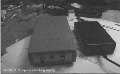
I also had a computer 12V 3A switching power supply laying around for use as a 110 supply (Photo 3). I connected it to a set of JBL L 100s in my office fed with a Luxman tube preamp, with a Philips CD player and a Luxman FM tuner. The sound was tight with substantial bass using a variety of sources and music. Even turning the volume up substantially resulted in a very loud signal, before clipping set in (I am not really sure it was clipping or just the 10%). I reduced the volume to a comfortable listening level and proceeded to spend a few hours listening while I worked on other projects.
I also evaluated it outdoors driven with an iPod as a music source, and a small set of mini monitors. It turns out the outdoor use was better for this amp. I experienced the same thing when I listen to commercial solid-state amplifiers — listening fatigue. I wouldn’t say it sounded bad; it just didn’t light me up.
ALTERNATIVE
The next experiment was with the 4 x 100W module
• 4CH D Class amp
• 75W 4CH (THD 1% 41
• 150W4CHC2c
• Full bridge output
• 1 Input power
• Free Voltage (6V, 26V)
• Protection (thermal, overload)
• Analog signal input
• High Power efficiency up to 90% (2CH OUT at 30W)
• No On/Off Pop Noise (Sleep, Mute) Operating Environment Temperature Range: 0 C
Storage Environment Temperature Range:-25 C-- +85C
Outline Dimension 5.7 x 5.7”
Item Net Weight: 400g/14.3oz
The size of this unit is pretty impressive, only 5.7” x 5.7”, yet it will provide four channels of 100W (Photo 4). The switching power supply I purchased is also pretty compact yet will provide 12A of current at 24V. I played around with several ideas for a case for this amp and decided to make one out of some scrap wood and plexiglass. I have made a number of chassis with this technique and they typically receive a very positive response from the eventual owners. I buy scrap pieces of plexi from a large hardware-type surplus store. Photo 5 shows the final cabinet.
IMPRESSIONS
So how did it sound? I hooked it up to the same system as before and started working it out. I was struck by how quiet the amp was. There is no perceived sound coming from the speakers. Apparently, the switching power supply noise was effectively filtered out by the output filtering network. I was pretty impressed by the available power. This amp produced very solid bass and seemed very clear in the midrange and treble regions. I listened to the amp for several hours and found the same type of listening fatigue I experienced with the smaller unit.
Not wanting to be completely prejudiced, I asked my buddy Larry to listen to it for a while. As I have mentioned in previous articles, Larry is a McIntosh fanatic and believes their vintage tube equipment is the best sounding equipment you can own. He hooked up the amp to his reference system in place of his MC 60s. I didn’t reveal my impressions and let him listen to the unit for a couple of weeks. One day he brought the amp over and told me he didn’t like it. Usually Larry is pretty diplomatic about my projects, so I was a little surprised by his assessment.
He thought it had pretty harsh mid-range, and while the treble was airy, it wasn’t natural. He said the bass was impressive, with several instances of the house vibrating from the music. He listens to many different kinds of music, and tried to use a variety with this amp. He said the one that was the most telling was Alison Krauss, whose vocal range and ability is pretty impressive.
Overall, our impressions were similar. But I work in the medical research area and am skeptical of any trial that isn’t double blind and randomized, so a trial of two, with no blinding, is not very impressive.
We both thought that the sound was clean but sterile, the bass solid and tight with mild midrange. Even though each of these modules provides turn-on suppression, they both exhibited some turn-on noise and mild thump. Once powered up, they were extremely quiet, even though they were being powered by switching power supplies.
I am going to attempt to listen to a Bel Canto Evo power amp to see how a very expensive Class D amp really sounds. Most of the sources of information I accessed for this article agree that there can be very impressive Class D amps built with advances in manufacturing and technical development.

PHOTO 4: Module.
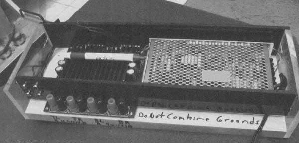
PHOTO 5: Final cabinet.
REFERENCES: