1. Solder Paste and Reflow
Solder paste has long been associated with surface mount construction and rework. Its use for hand working is a matter of personal preference. One application where it has a definite advantage is for board population where a solder mask is present. Here a small blob of solder paste is applied to each solder pad, about one-third its area. The chip components are then put in place and the residual tackiness of the paste keeps them there. The whole PCB is then placed in a reflow oven. The temperature is now increased to about 30°C to 40°C above the alloy melting point for less than 10 seconds. At the reflow temperature the paste decomposes and the solder coalesces, wetting the components' solder contacts and the copper lands.
A great advantage of this process is that the chips can be placed on the solder pads with little accuracy. At the reflow temperature the chips float on the solder and are pulled into alignment with the printed solder mask. Hot air can be used to reflow the solder paste on an individual basis for a small prototype. It is not unknown for a small PCB to be placed under a domestic grill to reflow it, but extreme caution is required to get even heating without hotspots. Similarly hot air paint strippers are a source of suitable heat but again great care please, and no complaints if it goes wrong. This is the beginning of a new age of amateur construction and experimentation and improvision is the name of the game. Reflow ovens suitable for small scale batch-wise and prototyping use are available from specialist SM suppliers.
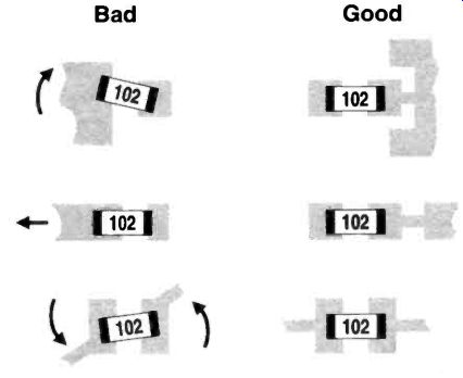
Fig.54 Non solder-masked lands for solder cream.
A non-solder masked project can be reflow soldered provided the copper land area is kept small and suitably shaped.
Ideally this will be a small rectangular pad with a narrow track running to it, not a vast expanse of copper as preferred for hand soldering (Figure 54).
At reflow the solder will, more or less, be contained by the pad and give good chip alignment. Of course a spot of glue, possibly on a dummy land between the pads, will hold the chip in place whatever the pad shape. Rework of glued-in chips is not so convenient. SM adhesives of various types are available for this purpose. Hand operated dispensers which will take a syringe of solder paste or adhesive can be obtained from SM suppliers. They are easier to use than manual syringes because they have lots of mechanical gearing to make ejection of the paste easier. Solder paste for dispensing has a viscosity of 350,000 to 450,000 cP (mPa s), i.e. very thick. Population of non solder masked projects with solder paste is a viable technique for the amateur. Here reflow is easily achieved with one of the many portable butane soldering irons now sold widely, fitted with a hot air blower. The technique is to approach the solder joint slowly from several centimeters, gradually building up the temperature to the reflow point when the bright solder appears at the ends of the chip. Use a circular motion for larger chips in order to cover the area evenly. As soon as reflow starts, stop your approach and remove the heat as soon as reflow is complete. In fact the heat can be removed an instant before reflow is complete since the heat in the system will keep things going for a time. Solder paste is also useful for rework which we will cover later.
You might have guessed that there would be more than one type of solder paste. Yes, nothing is ever that simple. Overall it is dark grey in color as you might expect. Its consistency can vary from a moderately stiff paste for dispensing through syringe tips, to a very stiff paste for silk screen or stencil application with a viscosity up to 800,000 cP. The flux is rosin based but it can be straight rosin, mildly activated, or activated. Water soluble and low residue versions are also available. The third global specification is the type of alloy. Most are lead/tin/silver but other metals can be added such as bismuth. The proportion of metals in the alloy determines the melting point. These are, in fact, eutectic compounds so that only certain ratios are possible. The metal content of a paste varies from 85% to over 90% and for dispensing, 85% total metal content is the norm.
For hand working and general purpose use you won't go far wrong with a 62/36/2 alloy. This is Tin (Sn) 62%, Lead (Pb) 36% and Silver (Ag) 2% which has a liquidus point of 179°C.
A suitable flux would be a mildly activated rosin type and the formulation needs to have a low viscosity around 400,000 cP as dispensing from a syringe is the best way to apply it. Looking a little closer we find that the organics in the formulation other than the flux have an important effect on the behavior before and during the reflow cycle. For fine pitch work a "restrictive flow" paste is recommended. Here the paste stays on the spot and does not slump near the reflow temperature, reducing the risk of bridging the leads. A normal non restrictive paste will slump and spread. For hand working it is a matter of personal choice. The solder particles in the paste are preferably spherical as this minimizes the oxide content. Particle diameter varies from 45 to 75 microns, the former being more suitable for fine pitch work. Some manufacturers refer to their high quality products as solder creams.
Solder paste for commercial use can have a limited storage life, especially if stored above 10°C. Refrigerator storage is normally recommended but certain products are less critical in this respect. Remember that solder cream contains lead in a highly divided form and is therefore best considered as poisonous. Handle it with great care and if you do come into contact with it don't eat your sandwiches before washing your hands with a strong detergent.
A simple balling test gives an idea of the quality of the solder cream. To do this place a small quantity of paste, about 0.2cc, on a copper-free area of PCB--for example, the reverse side of a single sided fiberglass PCB. Hit this with a hot air blower as though you were making a solder joint and watch how it behaves. It should end up as a single bright ball of solder. Any grayness or surface features indicate high oxygen content and if lots of little solder balls remain it is not a good cream.
Two types of dispensing tips are commonly used for solder cream and adhesives--the tapered, all polypropylene type which is about 1.5" in length and the blunt end stainless steel type Both have Leurlock fittings to standard syringes. The tapered types have lower tendency to block. A specially made dispensing gun will have a suck-back feature which helps to deliver a precise quantity of solder cream.
2. Rework and Repair
In approaching an SM circuit with a view to troubleshooting and repair we are confronted with the problem of measuring voltages, following signals, and inspecting as in a TH circuit but on a much smaller scale. Meter probes need to be smaller and there is a greater risk of accidental shorting. Joints are smaller and inadequacies in soldering are much more significant. Removal of defective components, without PCB damage, is not difficult and if tackled with appropriate equipment it is probably more convenient than removal of a TH device. Again, an advantage of SM is the fact that for simpler circuits at least, everything is laid out before you on one side of the PCB.
If you are designing the PCB it is a good idea to build in a few significant test points to avoid having to contact SOIC leads with a probe. In any case some fine probes will need to be engineered and the simplest way is to file or turn down some standard probes. For digital systems there are IC test clips but unfortunately there are several types of ICs.
Checks for mechanical failure are often the first approach to fault finding and indeed things that move, plugs and sockets, relays are often the culprit. Over dissipation, voltage break- down and the like are design faults and more likely to appear on project circuits rather than commercial products. Component failure is associated with product age, particularly if the product is used in an unfriendly environment. High temperature and humidity, frequent power on/off cycling and operation near its design limits will increase ageing. In any case inspection followed by component replacement is the usual scenario.
The array of magnifying aids described previously will be needed for soldered joint inspection. Joint failure is likely to be the result of poor formation in the first place, but temperature cycling or direct mechanical stressing can fatigue a joint as described in Section 5. Adding more flux and re-soldering is the obvious action, removing excessive solder as required.
Dealing with components is another matter and you may need to be inventive, particularly if not fully equipped.
Chip capacitors and resistors have very good tolerance to mechanical stress within their design limits. However, resistors can lose their ends in extreme conditions of bending. Chip capacitors of the C0G type are very robust. Higher dielectric constant materials, particularly Y5V/Z5U, are quite brittle and can simply crack in a very visible way, but sometimes a crack is not so obvious. The end contacts are the weak link as far as mechanical stress is concerned and they can become wholly or partly severed. This is more difficult to detect. The reliability of tantalum capacitors has improved greatly but dead shorts or loss of performance should not be ruled out in cases of mysterious behavior.
Passive components are the easiest to rework, but both ends of the chip must be melted at the same time before the chip can be lifted off its pads. If you are dealing with, say, a 1206 chip resistor, two soldering irons could be used. One problem here would be the presence of an adhesive in which case a slight twist in the plane of the PCB will fracture the bond. A similarly crude method is to fracture the chip with side cutters. Each half can then be conveniently removed with iron and tweezers.
A more satisfactory approach is to use a hot air blower. Get ready with the tweezers, approach the chip slowly and as the solder melts pick the chip off. Next clean up the pads with solder wick, flux them, and solder in the new chip.
Alternatively put a couple of dabs of solder cream on the clean pads and reflow the new chip in place with hot air (or a soldering iron). Servicing with hot air can be problematic on compact circuits, for instance, melting the solder on adjacent chips. It may be necessary to construct a screen with a little PCB or aluminum foil. With purpose-built hot air rework tools some very fine nozzles can be used, reducing the need to screen. A vacuum pen is very handy for picking off de-soldered chips and a delight to use. Less precision is needed as it will just snap up the chip from any angle of approach. Normal tweezers have to be positioned to get the right grip and they often slip on the smooth surface of the SMD.
Several companies make a series of rework tips for fitting to their soldering irons. These are convenient to use and are almost essential for SM work. Coupled with a vacuum pick up pen these rework tips ease servicing. Two points are worthy of note however. First you need to change the tip to remove a different type of chip and a dedicated iron for your most used rework bit(s) is a practical solution. Secondly, the space to get the rework tool to both ends of the target chip is sometimes restricted. Some makes of rework bit are a little slimmer but there are price differences. Some rework tools suitable for the more popular chip components are shown in Figure 55.
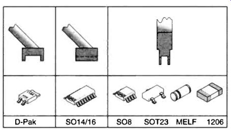
Fig.55 Soldering iron rework bits--D-Pak S014/16 SO8 SOT23 MELF 1206
Removal of an integrated circuit creates the biggest problem for the service engineer but again happiness increases in pro portion to money spent on gadgets. Fortunately SOICs up to say 16 pins can be managed with a hot air blower. Circulate around the chip until the solder melts and then pick it off with a vacuum pen or tweezers. Clean up with solder wick and reflux as before. In this case it is probably best not to remove any solder before the chip is removed as it acts as a heat store between hot air passes. A less sophisticated method is to remove as much solder from each pin with solder wick and then bend each pin back slightly until the chip is free. We SMDers generally do not use solder suckers. The shock produced is regarded as unhealthy for our little ones.
Another low tech method consists of threading a loop of enameled wire under one edge of the chip. This is then pulled under the pins as they are melted. Cutting off fine pitch leads with SM quality side cutters has also been advocated. The pin ends are then removed individually.
The two soldering iron method is adopted by a number of equipment manufacturers in the form of heated tweezers. These have replaceable tips suitable for a wide range of SMDs from resistors to PLCC chips. They certainly make chip removal easier and can tackle some of the larger ones. The tips melt the solder and grip the package at the same time. Some of the professional rework tools have a vacuum sucker in the center which lifts the chip as the solder melts. This is a neat solution to the difficult problem of picking up the chip when it is enclosed on all sides with a hot rework tool. A rework tool of this type is almost essential for the very large items like the 144 pin QFP chips. Such a chip is probably more easily dealt with using a hot air rework head supplied with the higher quality rework stations. In hot gas types the heat is directed to the leads by a set of very fine tubes and as the solder melts a vacuum sucker picks up the chip. More sophisticated repair work some times involves heating the whole PCB up to a certain temperature approaching the reflow temperature of the solder so that when a solder joint is melted there is minimal temperature difference and less thermal shock. The point is not to attempt a repair on anything that you think may need this kid-glove treatment. Some time spent in rework practice with a scrap circuit board will be useful.
Repairs to damaged tracking is possible with adhesive copper tracking. This is aimed at the specialist and as it is very fine, considerable skill is needed.
3. PCB Protection
However pragmatic your approach to design, population and completion of an SM project, it is in your interest to work neatly and to consider the electrical and physical requirements of the chips. Protect them from moisture ingression, from dust which may be conductive and from stress forces resulting from PCB bending or excessive temperature cycling. Apart from all this, a neat layout is pleasing to the eye and adds to the satisfaction of completing a piece of artwork.
Many fluxes have a degree of acidity and after being subjected to soldering temperatures, when partial chemical break down and combination with the solder occurs, are conductive to some degree. It is therefore highly advisable to remove them from the PCB. Solder pastes can be of the low residue type but some can contain acid donor salts like zinc chloride and other compounds which can interfere with circuit performance. For example, the conductivity of the flux residue can vary with humidity. Whatever type of solder paste is used the circuit board should be cleaned. Proprietary cleaners are alcohol based or 1.1.1 trichloroethane based. All work excellently but the chloro-ethane type dries very fast. This latter type is best used in a well ventilated area.
After the circuit has completely dried a protective coating can be applied. The simplest is a clear solder-through lacquer.
This is adequate for most purposes and will keep your circuit looking good. A neutral rosin based flux applied from an aerosol is not too bad as a protective coat and certainly makes rework easier. Silicone based conformal coatings are thicker and offer more protection. They can be solvent removable or solvent resistant. Before applying a conformal coat, adjustable items like trimcaps and presets may be protected with a peelable mask. This comes in the form of a latex cream which cures to a strong rubber, it can be peeled off after the conformal coating has dried. Test points can likewise be protected. It is probably not a bad policy to protect all variable devices in this way whether further adjustment is needed or not. The invading conformal coat may alter the electrical value of the device.
And finally, I have introduced many gadgets which make SM work effective but you should not be deterred by this. Very satisfactory results are possible with minimal equipment. The most important decision is to have a go.