In this first section, we will investigate how to plan the mechanical layout of a tube (valve) amplifier. At this stage, freedom of choice is unlimited, whereas later it will be restricted. So it is important that the choices and compromises made now are the best ones. Whilst good planning will not save a poor design, poor planning can certainly ruin a good one.
Chassis layout
Tube (valve) amplifiers use a number of large components that must be positioned relative to one another such that the connecting wires between each component are as short as possible, but that the components and their associated wires do not interfere with each other. Chassis layout breaks down into the following considerations:
-- Electromagnetic induction: Minimizing hum induction from chokes and transformers into each other and into tubes.
-- Heat: Output tubes, etc. are hot and must be cooled. Conversely, capacitors run cool, and must be kept that way.
-- Unwanted voltage drops: All wires have resistance, so the wiring must be arranged to minimize any adverse effects of these voltage drops.
-- Electrostatic induction: Minimizing hum from AC power wiring is not often a problem, because even thin conductive foil provides perfect electrostatic screening.
-- Mechanical/safety: Achieving an efficient chassis arrangement that is easily made, maintained, and used.
-- Acoustical: Almost all components are microphonic, but tubes are the worst. We should consider which components are most sensitive to vibration, and minimize their exposure to it.
-- Aesthetic: The highest expression of engineering is indistinguishable from art. If you have a superb chassis layout, it will probably look good. Conversely, if it looks poor, it is probably a poor layout . . .
We have a seven-dimensional problem. A poor transistor amplifier might be able to hide behind the fence of negative feed back, but tube (valve) amplifiers using an output transformer cannot usually tolerate more than 25 dB of feedback before their stability becomes distinctly questionable. Consequently, layout is critical to performance.
The large components are generally the mains transformers, output transformers, power supply chokes, power supply capacitors, and tubes. The traditional way of deciding how to position them is to cut out pieces of paper of the same size as the components and shuffle them around on a piece of graph paper. Alternatively, the lumps themselves can be arranged and glanced at for a few days until the best layout presents itself.
Even better, components can be shuffled around and a chassis designed using an engineering drawing package on a computer, with the enormous bonus that a template of the layout can be printed with all the fixing holes precisely positioned, saving errors in marking out. Although it takes time to draw a tube (valve) holder or a transformer precisely, it has only to be done once and you will quickly build up a library of mechanical parts. In consequence, the author has almost forgotten how to perform traditional marking out using a scriber, ruler, and square.
It is vital to make the chassis large enough! This point cannot be emphasized too strongly. Achieving neat construction on a cramped chassis requires a great deal more skill and patience than on a spacious chassis. There are many considerations that must be taken into account, so it is vital that this stage is not rushed. Each of the following design considerations might not make a great difference in itself, but the sum of their effects is the difference between a winner and an ''also ran''.
Electromagnetic induction
Almost all of the larger components either radiate a magnetic field or are sensitive to one. Not all of a transformer's primary flux reach the secondary. Leakage flux can induce currents into wires such as tube (valve) grids. Whether, or not, these currents are significant depends on the signal level and source impedance at that point, so output tubes are less of a problem than the input stage.
Coupling between wound components Wound components such as transformers and chokes can easily couple into one another, so hum can be produced by a mains transformer inducing current directly into an output trans former. Fortunately, the cure is reasonably simple, and may be summarized by a simple ratio whose value must be minimized.
induction = cos θ / d3
The angle theta and distance d are shown in the diagram (see FIG. 1).
Rotating transformer cores by 90 degr. (cos 90 degr. =0), so that the coil of one transformer (or choke) not aligned with the other is very effective, and typically results in an immediate 25 dB of practical improvement. Even better, if one coil is driven from an oscillator whilst the interference developed in the other is monitored (oscilloscope or amplifier/loudspeaker), careful adjustment of relative angles can often gain a further 25 dB.
Because coupling decays with the cube of distance [1], as the distance between offending items is increased, the interference falls away rapidly. However, simply increasing the gap between two adjacent transformers from 6 to 25mm does not materially reduce the interference, because the transformers are typically 75mm cubes, and the spacing that applies is the distance between centers, which has only changed from 81 to 100mm, resulting in only 5.5 dB of theoretical improvement. In practice, when the transformers are this close, coupling does not obey the cube law very well because the transformers do not see each other as point sources, so a 3 dB reduction, or less, is more likely.
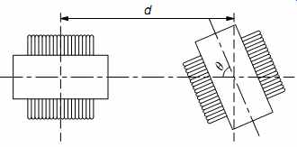
FIG. 1 Orienting transformers for minimum coupling
Although smoothing chokes are gapped, and therefore inevitably leaky, they do not generally have an appreciable AC voltage across them. So their AC leakage is low, and they can often be used to screen output transformers from the mains transformer. The exception to this rule is the choke input power supply which has a substantial AC voltage across its choke, so its leakage field is capable of inducing currents into surrounding circuitry.
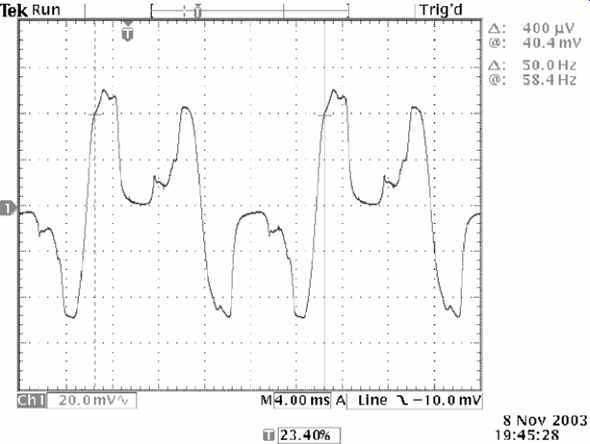
FIG. 2 Leakage flux caused by an unscreened saturating mains transformer
The core of a poorly designed mains transformer can easily be saturated by the large current pulses drawn by a large reservoir capacitor in combination with a semiconductor rectifier, producing a particularly noisy leakage flux, and this can be quickly identified by a search coil (see FIG. 2).
A screening can that totally encloses a transformer significantly attenuates the high frequency content of any leakage flux. The second guilty party is a fifty-year-old mains transformer whose core material has deteriorated, but this transformer is totally enclosed by a thin steel screening can. Note that the waveform has smoothly rounded edges, indicating far less high frequency content than the previous example (see FIG. 3).
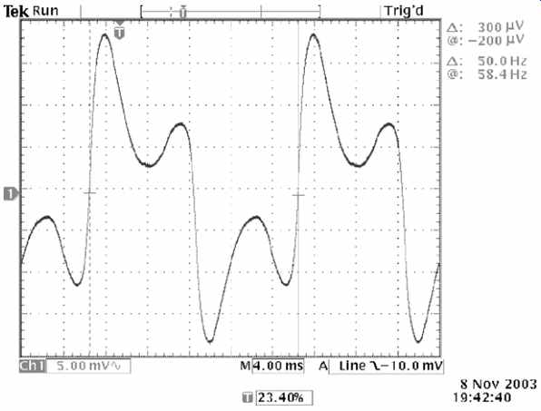
FIG. 3 Leakage flux caused by a screened saturating mains transformer
Transformers and the chassis
All transformers leak flux. The question is whether that is a problem. If an output transformer leaks flux into the aluminum chassis of a power amplifier, it probably isn't a problem because aluminum doesn't conduct magnetic flux. But a mains transformer leaking flux into the steel chassis of a pre-amplifier is a problem because the steel chassis passes the flux into sensitive signal circuitry. Fortunately, because μ=0 for non magnetic materials, but μ>5000 for iron, even a small gap is able to prevent flux leaking into the chassis. A 1-2mm paxolin sheet is ideal, but this may be hard to find. So a (more expensive) alternative is the polystyrene sheet sold by model shops. (Although un-etched FR4 PCB material would be ideal, if the copper side were to be placed in contact with an aluminum chassis, it would electrolytically corrode it, whereas the face-up copper would oxidize quickly and become unsightly.)
Beware that practical toroidal transformers leak flux and that mounting a toroid directly onto a steel chassis is just asking for hum problems. However, the danger of accidentally creating a shorted turn is even greater. Toroids are secured by a conductive screw pulling a large conductive washer onto the top of core to clamp the transformer tightly to the chassis. Accidentally connecting the washer or screw to the chassis by any means other than the bottom of the central mounting screw would form a shorted turn that could destroy a power transformer.
Beam tubes and mains transformers
Beam tubes focus their current into thin sheets that pass largely unintercepted between the horizontal wires of g2.This means that a vertical beam deflection would affect g2 current, and because g2 is typically supplied from a finite source resistance, Ohm's law ensures that this would change Vg2, thus changing Ia. One way of deflecting electrons is with a magnetic field, such as the hum field from a transformer. Hum due to beam deflection can be minimized by applying Fleming's left hand rule, and ensuring that the electron beam is never at right angles to the leakage flux from the transformer. When considering induction between two transformers, it does not matter which transformer is rotated, so long as the coils are at 90 degr. to one another. With beam tubes, only one orientation is ideal with respect to a nearby mains transformer (see FIG. 4).
The tube (valve) is shown in two positions, both the same distance from the center of the mains transformer, and both with correct beam orientation relative to the leakage flux from the transformer. However, leakage flux tends to be concentrated on the axis of the coil, and would also induce hum into the control grid's circuit, whereas the alternate position has much lower flux density. (Diagrams of this form portray higher flux density by having more lines in a given area.)
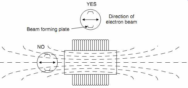
FIG. 4 Beam tubes and mains transformers
Input tubes are very sensitive to hum fields, and should be placed at the opposite end of the chassis to the mains transformer.
In theory, output transformers should leak less because they operate at a lower flux density (to reduce distortion). In practice, probing output transformers and mains transformers with a small search coil failed to show the expected difference.
The quality of the transformer seems to be the over-riding consideration, rather than its use. Thus, a Leak TL12 + push-pull output transformer leaked more flux than a good-quality modern output transformer in a single-ended amplifier, despite the latter being gapped.
Although, as expected, leakage flux at 90 degr. to the coil's axis cancels to zero, leakage at the edges of the coil can be comparable with that on axis because the coil's outermost turn is so far away from the (flux-concentrating) core (see FIG. 5).
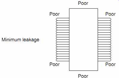
FIG. 5 Transformers leak most flux along the axis of their coils and where
the edges of their coils are furthest from the core
Heat
Heat is the enemy of electronics. Output transformers and chokes are usually quite cool, so they can move towards the center of the chassis if necessary (creating a mechanical problem, but we will consider this later). Mains transformers are generally warm, and it is usually best to mount them towards the edge of the chassis.
At best heat shortens component life and causes components to drift in value. At worst, it causes fires. And we intend to use tubes, which are deliberately heated.
Modes of cooling
There are three methods of transferring heat from one place to another.
Conduction is the most efficient method of heat transfer and requires a conducting material to bond the heat source physically to its destination. An ideal conductor would transfer the heat without any temperature drop between source and destination, and materials having free electrons (electrical conductors) such as copper and silver are particularly good. As an example, the body of a power transistor must conduct the heat generated by the (very much smaller) silicon device to an external heatsink efficiently (see FIG. 6).
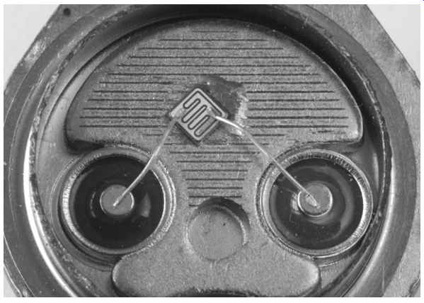
FIG. 6 The inside of a 2N3055 15 A 115W power transistor. Note the relative
size of the silicon device and its wires compared to the case.
Convection relies on the unrestricted movement of a fluid (gas or liquid) between source and destination. Fluid is heated at the source, expands, and is displaced by denser cooler fluid, forming a convection current which continuously pushes hot fluid away and draws cool fluid towards the source. Convection efficiency can be increased in two ways:
-- If a greater volume of fluid moves per second, more heat can be lost, so a fan or pump greatly improves heat transfer. The pumped water in a water-cooled internal combustion engine or central heating system is an example of forced convection.
-- We choose a fluid that requires more energy for a given temperature rise. Liquids are better than gases, and water is particularly good. However, although some transmitter tubes have water-cooled anodes, practical pipe diameters and pump power mean that there is a limit to the maximum flow rate, and thus the heat that can be transferred. Even better, changing the state of a material requires a great deal of energy, and converting water at 100 degr. C to steam at the same temperature requires six times as much energy as heating the same mass of water from 20 to 100 degr. C, so the largest tubes are steam cooled.
Radiation (strictly, electromagnetic radiation) does not require a physical medium between heat source and destination, but it is the least efficient means of transferring heat. Radiation losses are governed by Stefan's law:
E =~ &dsigma;T^4
Where:
E=power per unit area
σ =Stefan's constant=5.67x10^-8 W/K^4/m^2
T=absolute temperature= degr. C+273.16
Because heat loss is proportional to the fourth power of temperature, particularly hot bodies, such as the Sun, can transfer heat quite effectively by radiation.
Tube (valve) cooling and positioning
Output tubes are hot, and must be allowed to cool properly.
Typical audio tubes place the anode within an evacuated glass envelope, so the anode cannot lose heat by convection. The supporting wires from the anode to outside connectors are quite thin, so the anode cannot lose heat by conduction. The only remaining method of heat transfer is radiation.
Radiation obeys reciprocity, in that a good reflector is a good insulator, so domestic kettles are shiny metal or white plastic.
Conversely, matt black absorbs well, so anodes are often blackened to allow them to radiate more efficiently.
Although we think of glass as being optically transparent, some light is inevitably lost in transmission. Similarly, glass is imperfectly transparent to infrared radiation. Radiation that is not transmitted is absorbed and heats the glass. So some of the received heat from the anode can be lost by convection if air is allowed to flow freely past the tube (valve) envelope. Very roughly, the envelope splits heat losses from the tube (valve) equally between convection and radiation. Thus, efficient cooling requires that we consider how a tube (valve) can radiate, and how easily convection currents can flow past the envelope.
Power tubes should be separated from one another by a spacing of 1 1/ 2 envelope widths or more, otherwise they heat each other by radiation. But a useful trick can be applied to the radiant heat received by a valve. Many tubes, particularly small-signal tubes, have an anode with quite a narrow cross section. Received radiant heat is proportional to the area seen at the destination, so rotating a tube (valve) to present a narrow cross section to the source can reduce heating from adjacent power tubes. By reciprocity, if the source also has a narrow cross section, rotating the source to present a small area to the destination also reduces transmission. This technique is particularly useful for circuits such as differential pairs or phase splitters where electrical considerations dictate that the two tubes be close together, but it can also be used to reduce heat received from a nearby power tube (valve) (see FIG. 7).

FIG. 7 Careful anode orientation allows closer spacing along the anode's
narrow axis
Placing power tubes in the middle of a chassis is not likely to be a good idea because the chassis severely restricts convection currents. Mounting a tube (valve) horizontally can improve convection efficiency because it exposes the envelope to a larger cross section of cooling air. However, this could conceivably cause a hot control grid to sag onto the nearby cathode, with disastrous results. So check the manufacturer's full data sheet to see if there are any strictures about mounting position. If it doesn't cause other problems, align the socket so that the plane of the grid wires is vertical [2], preventing them from being able to sag onto the cathode.
Early tubes have cylindrical electrodes, so viewed down their axis, electrons strike the anode equally from all points of the compass. Since the electron density is equal at all angles, the anode temperature is also equal at all angles. However, beam tetrodes do not have axial symmetry, and direct their beam of electrons along a single diameter, causing the anode to heat unequally. Bearing in mind that the glass envelope converts half of the radian the at loss from the anode to convection loss from the envelope, a horizontally mounted beam tetrode should be rotated on its axis so that the hottest parts are at the sides, allowing them to be efficiently cooled by convection, rather than at top and bottom. As an example, see GEC's recommended alignment for the KT66 [3] (see FIG. 8).
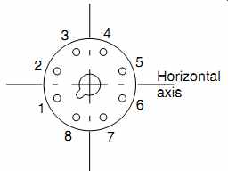
FIG. 8 GEC recommended orientation of tube (valve) base for horizontally
mounted KT66.
Because the sections of a KT66's envelope between pins 1 and 2, and 5 and 6 are the hottest, when mounting a push-pull pair of KT66 vertically, it makes sense to ensure that pins 7 and 8 of one tube (valve) face pins 7 and 8, or 3 and 4, rather than 1 and 2, or 5 and 6.
Mounting tube (valve) sockets on perforated sheet greatly assists cooling by allowing a convection current to flow past the valve, but as the hole area of such sheet is typically only _40%, it is still not perfect. If better cooling is needed, the tube (valve) socket can be centrally mounted on a wire fan guard, and if even that isn't sufficient to keep the envelope temperature below the manufacturer's specified maximum, a low-noise fan can be mounted on pillars underneath the chassis using the same screws that secure the fan guard (see FIG. 9).
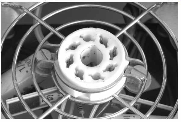
FIG. 9 With care (and large washers), a tube (valve) socket can be mounted
on a fan guard, allowing almost unrestricted airflow.
Using the chassis as a heatsink
Some small components such as power resistors and regulator ICs, unavoidably generate significant heat. Resistors are commonly mounted on stand-offs to allow an unimpeded air flow, and regulators are often fitted with small finned aluminum heatsinks. Neither of these strategies is ideal because they attempt to lose heat by convection to still air enclosed by the chassis.
Convection cooling only works if there is a free flow of cooler air past the hot component. Once the cooling flow stops, the hot component is surrounded by still air, which is a good insulator, and its temperature quickly rises. Eventually, the still air begins to lose its heat by conduction to the surrounding chassis, and an equilibrium results with a high internal air temperature and a hot component.
A high air temperature within the chassis is undesirable because:
-- The components causing the high air temperature are unnecessarily hot, and even though they may have been designed to withstand heat, their working life is inevitably reduced.
-- Electrolytic capacitors are extremely sensitive to heat, and a very rough rule of thumb is that their working life halves for each 10 degr. C rise in temperature. Capacitor manufacturers' data sheets include extremely useful charts that allow lifetime pre dictions to be made from ambient temperature and capacitor ripple current, so it is well worth looking up the full data sheet for your particular capacitor at the manufacturer's website.
-- Components having a critical value, such as in equalization or biasing networks will drift away from their optimum value as a consequence of heating from the air.
Ultimately, we can only lose heat to the surrounding air, and the larger the surface presented to the air, the more efficiently it will cool. This means that the best way to cool components is to ensure that they are thermally bonded to the chassis, using a thin smear of heatsink compound.
Heatsink compound is not a particularly good conductor of heat, but it is far better than air. The purpose of heatsink compound is to fill the tiny insulating air gaps that result from placing two imperfectly smooth surfaces together. Too much compound worsens cooling. Most people (and this includes manufacturers) use too much. A thin, even smear applied to both mating surfaces is all that is required. Beware that the screws bonding the bracket to the chassis can loosen at operational temperature. So check them for tightness when fully warmed-up, otherwise the compromised thermal bond can cause the semiconductors to be hotter than expected, and worse, the erratic bond can cause drift.
A useful secondary advantage of mounting aluminum-clad or TO-220 resistors directly onto the chassis is that they provide convenient mounting tags for other components. It may seem unnerving to touch a chassis with hotspots due to local heat sinking, but this technique minimizes the internal air tempera ture, and thus minimizes the heating of sensitive components.
Efficient convection requires a free flow of cool air to replace hot air. Although most designers recognize the importance of allowing adequate ventilation by providing holes in the top of a chassis near hot components, air must also be free to enter the chassis from the bottom if an efficient convection current is to flow. Thus, the ideal solution is to make the entire underside of the chassis from perforated steel or aluminum, and support it on feet _20mm high (to allow air to flow into the underside of the chassis) (see FIG. 10).
If necessary, individual components can be cooled even more efficiently by bonding them directly to a finned heatsink fitted to the outside of the chassis, as is common with transistor amplifiers. Although this technique most obviously springs to mind when considering large power amplifiers or power sup plies, precision pre-amplifiers should have their internal temperature rise minimized in order to prevent equalization networks drifting in value, so it could be worth bonding anode load resistors to an external heatsink.
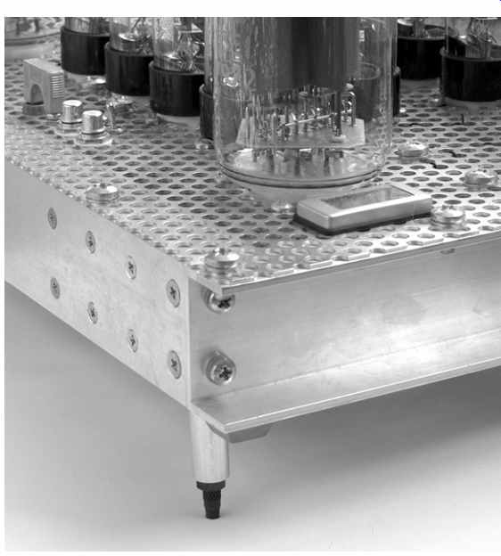
FIG. 10 Perforated sheet and tall feet allow excellent cooling
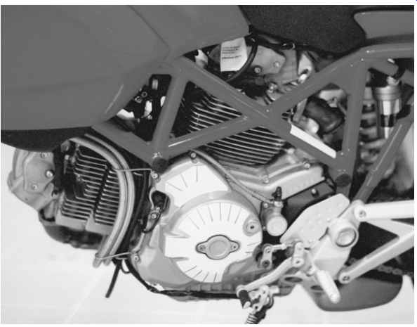
FIG. 11 Ducati Monster has barrels with fins aligned in the direction
of air flow
When finned heatsinks are used, it is most important to orient them correctly. Heatsink manufacturers specify thermal resistance ( degr. C/W) with the fins vertical in free air because this maximizes the surface area available to the natural cooling convection current flowing up the fins. Despite this, the author has lost count of the number of commercial amplifiers having horizontal heat sinks. Heatsinks cost money, so why degrade their performance? The prettiest example that the author can find of the importance of the correct fin direction is a motorcycle (see FIG. 11).
The engine is a V-twin. The pistons are identical and run in barrels that are detachable from the crankcase. Despite the increased production cost, the two barrels are different, one having longitudinal fins, the other latitudinal, and this is done solely to optimize cooling. Your amplifier's fins do not have a forced 100mph horizontal convection current, so they need to be vertical.
Cold tube (valve) heater surge current
The resistance of a conductor such as a tube (valve) heater filament changes significantly with temperature in accordance with the following equation:
Rt = R0 (1 + alpha t)
Where:
R0 =cold resistance
Rt =resistance at temperature t
alpha=thermal coefficient of electrical conductivity (0.0045 per degr. C for pure tungsten)
t=temperature change
Normally the temperature rise of conductors in electronics is too small for the effect to be noticeable, but a thoriated tungsten filament operates at ~ 1975K, so that at an ambient temperature of 20 degr. C (293K), its resistance is much lower, and theory predicts that it very briefly draws 8.6 times the operating current. In practice, the surge current is limited by the current capability of the supply, perhaps to only half the predicted value.
Indirectly heated tubes operate their filaments at ~1650K, resulting in a theoretical surge current of ~7 times the operating current, although measurements suggest that a ratio of ~5:1 is more appropriate. More significantly, the thermal inertia of the cathode sleeve slows heating, so the surge current lasts for a few seconds, and could be sufficient to blow a poorly chosen mains fuse. Further, it would not be prudent to use heater wiring of a rating only just sufficient to cope with the steady-state current if long-term reliability were required.
Wire ratings
Wires have resistance, so passing a current causes self-heating (P=I^2 R). If the wire becomes too hot, the insulation may catch fire, so it is important to ensure that the wiring is rated appropriately for the current to be passed. This means that wire current ratings are determined by ambient temperature, ability to cool, and the temperature rating of the insulator. As a very rough guide to wires having PVC insulation:
Conductor diameter (mm) | Maximum current (A)
- 0.6 | 1.5
- 1.0 | 3.0
- 1.7 | 4.5
- 2.0 | 6.0
Component catalogues are good sources of information on the suitability of a particular wire.
High-temperature insulators (such as PTFE) allow a higher current rating than might be expected from a given conductor diameter, but the penalty is higher resistance, so voltage drops along that wire will be proportionately higher, and this can become significant in the capacitor/rectifier/transformer loop of a power supply.
Arcing and insulation breakdown should not be a problem at the voltages found within most tube (valve) amplifiers, but it is still advisable to maintain 2-3mm separation between conductors with a high voltage between them, unless each conductor is insulated. As an example, hardwiring with bare wire touching the surface of a capacitor with wound polypropylene tape insulation is not advised, but a sleeved wire touching the same capacitor would be unlikely to constitute a safety hazard.
Unwanted voltage drops
All wires have resistance which is proportional to their length, and inversely proportional to their cross-sectional area.
Although the currents in tube (valve) circuitry are typically quite low, making the voltage drops proportionately low, once we consider that we want a signal to noise ratio of >90 dB, the voltage drops caused by small resistances become significant.
The highest currents, and therefore highest voltage drops occur in the loop from transformer via rectifier to reservoir capacitor and back again. A capacitor input filter draws pulses of current at twice mains frequency from the transformer that are typically four to six times greater than the DC load current. It is essential that the wires carrying these pulses are as low resistance, and therefore, as short as possible, which means that the rectifier and associated reservoir capacitor should be close to its mains transformer. It's the same logic that puts the battery in a car's engine compartment. (The original Mini was intended to be rear wheel drive from a 500 cc longitudinally mounted engine, but this proved to be underpowered, so the only way to fit a larger engine was to mount it transversely, but that left insufficient room for the battery, forcing it into the boot, requiring a long, very thick wire to the starter motor.) When an output stage enters Class B, it draws current pulses at twice the audio signal's frequency from the power supply. To prevent these pulses breaking into driver circuitry and increasing distortion, the loop from audio load to reservoir capacitor should be made as small as possible. This means that output transformers should be close to their HT capacitor.
The potential effects of unwanted voltage drops usually deter mine the 0V signal ground scheme, often known colloquially as grounding or grounding. There are fundamentally two methods of dealing with grounding:
-- ''Earth follows signal'': The 0V signal ground wire follows the path of the signal. In order to minimize unwanted voltage drops along this (necessarily long) wire, it has a large cross-section so this brute force strategy leads to 1.6mm (16 swg) tinned copper bus-bars.
-- Star ground: All connections to the 0V signal ground are made at a single point. Because the distance between individual connections is so small, the impedance is small, so unwanted voltage drops are also small.
The significance of these two wiring schemes is that the choice between them needs to be made at a very early stage. ''Earth follows signal'' tends to produce long slim mechanical layouts, whereas an ideally implemented star ground tends to produce square or even circular layouts centered about the star ground.
The significance of unwanted voltage drops is so great that it dominates the gross mechanical layout of an example later in this section, whilst detailed electrical implications will be covered in Section 3.
More powerful amplifiers are heavier, and in an effort to split the weight into two manageable chassis, you might consider having a remote power supply, necessitating an umbilical cable to connect between the chassis. Beware that the heater wiring linking the two chassis needs to be of a much higher current rating than normal in order to reduce the unwanted voltage drop over this increased distance, possibly necessitating an umbilical connector with a larger diameter cable entry.
Electrostatic induction
Electrostatic coupling is capacitive coupling. Minimizing the capacitance between two circuits minimizes the interference.
Remembering the equation for the parallel plate capacitor:
C = Ae0er / d
Where:
A =area of plates
d =distance between plates
e0 =permittivity of free space ~8.854x10^-12
er =relative permittivity of dielectric between the plates
We should aim to attack all parts of this equation to minimize capacitance. Reducing plate area means keeping wires short and crossing them at right angles, whilst increasing plate distance means keeping parallel wires apart. In terms of chassis layout, this means that the output tubes should be reasonably close to the output transformer and the driver circuitry should be reasonably close to the output tubes.
In a high-impedance circuit such as a constant current sink, a chassis-mounted transistor causes a conflict between thermal and electrostatic considerations because the collector is invariably connected to the transistor case. Screwing a TO-126 transistor such as an MJE340 to an grounded chassis using an insulating kit adds ~6 pF shunt capacitance, completely negating any efforts we may have made in designing a wide-bandwidth constant current sink. In this instance, we are forced to compromise our thermal considerations and lose heat directly to the air within the chassis using a small finned heatsink.
Fortunately, capacitance to chassis from aluminum-clad or transistor-style resistors used as anode or cathode loads is not a problem at audio frequencies. Because one end of the resistor is at AC ground, but the capacitance is distributed along the resistor, the total capacitance to ground is effectively halved, and because the impedances are lower than in a constant current sink, the stray capacitance becomes insignificant.
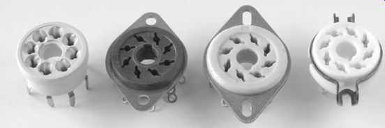
FIG. 12 Octal sockets. Note that the chassis-mount types all have different
mounting centers
Tube (valve) sockets
There is a variety of different types of tube (valve) socket available for a given tube (valve) type (see FIG. 12).
All three of the chassis-mounting International Octal sockets in the photograph have different spacings for their securing screws, so it is vital to make a firm decision about which socket type is to be used, and whether the circuit is to be hard-wired or PCB. One point that may be worth considering when choosing Octal sockets is that NOS McMurdo phenolic sockets have the same hole spacings as Loctal sockets, allowing an easy change from 6SN7 to 7N7 at a later date.
Another consideration is positioning of heater wiring. Taking the B9A base as an example, most tubes using this base have their heaters connected between pins 4 and 5, although heating the popular ECC83/12AX7 from 6.3V requires a link between pins 4 and 5, and the other heater wire must be taken across the center of the socket to pin 9. McMurdo B9A tube (valve) sockets were designed to that if the axis of the socket was aligned at 45 degr. to the edge of the chassis, pins 4 and 5 were closest to the chassis edge, minimizing hum from heater wiring (see FIG. 13).
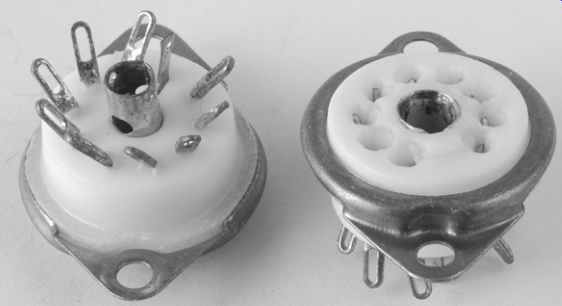
FIG. 13 McMurdo B9A sockets position the heater pins (4, 5) close to the
edge of the chassis provided that the mounting holes are at a 45 degr. angle
to the edge
Traditional tube (valve) amplifiers always had tube (valve) sockets aligned so that their heater pins were closest to the chassis edge, thus minimizing the length of exposed heater wiring . . .
How electrostatic screening works Electrostatic screening works by placing an grounded conductive barrier between the source of interference and the sensitive circuit (see FIG. 14).
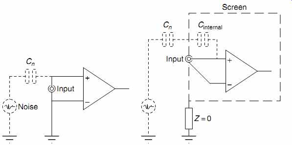
FIG. 14 Screening breaks one capacitance into two, center-tapped by an
ground
As can be seen from the diagram, the screen diverts noise currents from the source to ground. If there is any impedance between the screen and RF ground, the noise current can develop a noise voltage across it, causing the screen to induce noise into its enclosed (sensitive) circuitry.
Alternatively, the impedance from the screen to RF ground can be considered to be the lower leg of a potential divider, and the capacitance from screen to noise source the upper leg. The lower leg could be a length of conductor, which has inductance, thus forming a 12 dB/octave filter in conjunction with the capacitor. To maximize the effect of screening, the screen must have a low-resistance, low-inductance path to chassis.
When resistances and inductances are connected in parallel, the total value falls, so the screen should ideally contact the chassis at multiple points to minimize impedance and maximize screening. This is why RF designers cut the flanges of the lids containing their circuitry - it ensures that each finger firmly contacts the case, and minimizes impedance at RF (see FIG. 15).
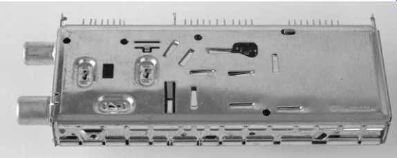
FIG. 15 Lids with fingers allow multiple low resistance, low inductance
contacts
From an audio point of view, screening cans should be firmly screwed to the chassis at multiple points using shakeproof washers to ensure a gas-tight connection that does not deteriorate over the years. Pre-amplifiers using choke interstage smoothing should ideally use oil-filled chokes, not because the oil confers any advantage, but because the metal can needed to contain the oil provides electrostatic screening.
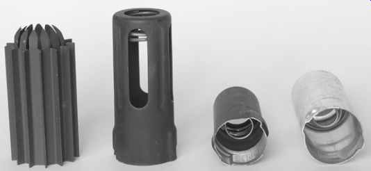
Tubes that are sensitive to electrostatic hum can be enclosed by an grounded metal screening can. Tube (valve) screening cans are not created equal. Perfect screening would enclose the tube (valve) completely, but that would prevent heat from escaping, making the tube (valve) significantly hotter, and reducing its life [2]. It is easy to raise a valve's temperature, but lowering it is much harder.
Screening cans are therefore a compromise between screening and cooling (see FIG. 16).
