by LES SOLOMON
DIGITAL logic circuits, whether they are in a simple counter or a complex computer, are formed from interlocking networks of gates and flip-flops. Observing such circuits as they operate is possible with a logic probe, a dc voltmeter, or a scope.
But since a logic probe or voltmeter can monitor but one signal at a time and the operation of digital circuits depends on the time relationships between a large number of signals, these instruments are of little help. A dual-trace scope does little better as it can be used to monitor only two signals.
What is needed is a way to monitor many signals simultaneously. The obvious solution, a logic analyzer, is costly. However, by taking advantage of some low-cost, readily available ICs, it is possible to construct a very inexpensive logic state analyzer that can display eight vertically displaced discrete traces on a conventional single-trace scope. Each trace will display the signals present on a selected input line. Thus, the timing of up to eight different points within a circuit can be simultaneously observed. The basic circuit is shown in Fig. 1.
Circuit Operation. The "heart" of the circuit is a 1-of-8 data selector that can accept eight TTL inputs and, via an internal address decoder, place one of the eight at a time on the chip output line. The inputs are selected by applying a digital code from 000 to 111 to the three address inputs of the data selector. When the enable pin (7) is held low, the chip operates normally.
The three address lines are driven from a counter (a divide-by-sixteen 7493, a decade 7490, or almost any other counter). When the clock input is driven, the three address outputs cycle continuously through the digital code.
The eight traces are developed from the three address lines by a rudimentary D / A converter formed by R1, R2, and R3 connected to the upper end of R5. When an address line goes high, current flows through the associated resistor and R5 to ground, developing a voltage across R5. With the circuit shown, an 8-step waveform is present for application to the scope vertical input.
Note the relationship between the weighted outputs of the counter and the associated resistors. If the scope horizontal sweep is properly adjusted, eight discrete traces will appear on the display. As a point of interest, slightly reducing the value of R1 will produce a small gap between the upper and lower four traces so that two "nybbles" can be displayed.
-----------------
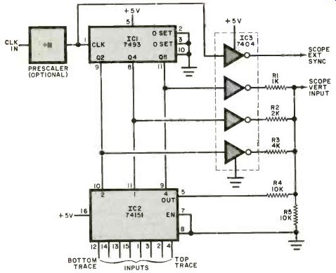
Fig. 1. Rudimentary D/A converter creates an eight-step wave-from. Scope sweep adjustment produces eight traces.
PARTS LIST
IC1-7493 divide-by-16 counter
IC2-74151 1-of-8 data selector IC3-7404 hex inverter
R1-1000-ohm, 1/2-watt resistor
R2-2200-ohm, 1/2-watt resistor (see text)
R3-4700-ohm, 1/2-watt resistor (see text)
R4, R5-10,000-ohm, 1/2-watt resistor
Misc.-Optional prescalers; oscilloscope connectors; colt r-coded 8-lead ribbon cable; grommets; suitable enclosure; miniature test clips; 14or 16-pin IC clamp-on; machine hardware; hookup wire; solder; etc.
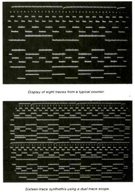
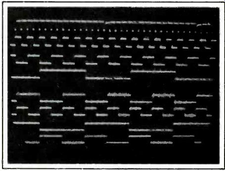
--------- Display of eight traces from a typical counter.
----- Sixteen-trace synthesis using a dual trace scope.
Resistor R4 is connected between the output of the data selector and the D/A converter. The value of this resistor determines the amplitude of the data selector output signal. Scope sync can be taken from the system clock or from other points in the countdown chain. If the clock is very fast, a 7490/7493/or equivalent divider can be used ahead of the main counter.
Eight traces are usually the limit for observation on a 5" scope CRT. However, if your scope has sufficient writing speed and you wish to display 16 traces, substitute a 74150 (1-of-16 data selector) for the 74151. Add an 8000-ohm resistor to the new address line and the top of R5. Note that theoretical resistor values are specified in the circuit. Use nearest standard values.
Construction. The simple circuit can be assembled on a small perforated (or a home-made pc) board, leaving room for two or three optional ICs. The basic circuit consists of IC1, IC2, IC3 and the five resistors.
Once assembled, the board can be mounted in a small enclosure; and, if desired, a low-power 5-volt supply can be added. Since the basic circuit requires about 72 mA, the analyzer can be powered from the circuit under test.
The scope sync and vertical input connectors can be mounted anywhere on the enclosure, while the 8-lead ribbon cable (one lead for each data selector input) exits via a grommeted hole. The +5-volt, ground, and clock leads exit via their own protected hole.
The 11 leads can be terminated as desired. The prototype used miniature test clips (Radio Shack 270-372, Calectro F2-916, or similar) to make the closely spaced IC pin connections. To examine a single IC, a 14- or 16-pin IC clamp-on may be used. When using such a clamp-on, the +5 volts and ground can be taken from the IC. Some form of identification must be used on each of the eight data leads.
Use. Connect the status analyzer to the +5 volts, ground, and clock of the circuit under test. Connect the analyzer ground and output to the scope ground and vertical input, and the sync to the scope external sync input. With operating power applied, adjust the scope sweep for eight discrete traces.
Any or all of the eight analyzer inputs can be connected to the logic under test.
Adjust the scope sweep and sync for a stable display. Once this is done, the value of R4 can be selected for the desired signal height on the traces. To avoid confusion, make sure that the signals do not overlap. Resistor R5 can be selected for a convenient signal level input for the scope.
Although this circuit is realized with TTL chips, a resourceful experimenter could build one using CMOS logic, following the same approach.
Source: Computers and Electronics--Experimenter's Handbook (1984)
Also see:
Cancel Rumble With This Bass-Summing Amplifier