BY JOHN H. DAVIS
Versatile project can also be used as an electronic crossover for a subwoofer power amp.
THE presence of deep bass in the output of an audio system adds a satisfying "floor" to reproduced program material. However, designing a system to reproduce low frequencies well heightens the probability that rumble will make itself disconcertingly apparent. Presented here is the Bass Summing Amplifier, a project that can attenuate rumble without adversely affecting the low-frequency content or the high-frequency separation of a phonograph disc. It can also be used as an electronic crossover that sums the extreme bass to feed a sub-woofer power amplifier. The Amplifier is easily and inexpensively constructed and requires no critical components or adjustments.
Rumble is low-frequency noise that is generated by phonograph recording and playback equipment. High-pass filtering can attenuate subsonic noise to a large extent, but it can't suppress audible rumble without also removing some desired bass content.
Most of the rumble entering a phono cartridge does so as vertical modulation that results in out-of-phase electrical signals at the phono cartridge's outputs. If these low-frequency out-of-phase signals are combined, they will cancel each other.
Since recordings contain little or no out-of-phase, low-frequency information, low-frequency summation does not appreciably degrade the program material. What little bass separation exists and is recorded is not audibly significant to human beings.. Psycho-acoustic studies indicate that bass localization is mostly a function of attack transients and overtones.
To verify that bass summing will attenuate rumble, play a silent groove on a vinyl disc and increase the volume until the rumble can readily be heard. Then switch your amplifier or preamplifier to its monaural mode. If your left and right channels are balanced and in proper phase, you will hear a drop in the rumble level.
About the Circuit. A schematic of the Bass Summing Amplifier appears in Fig 1. Line-level stereo inputs are applied to jacks JI and J2. Unity-gain inverters IC1A and IC1D shift the phase of the input signals by 180 ° . However, the unity-gain, low-pass filters comprising IC1B, IC1C and their associated passive devices do not appreciably alter the phase of those components of the input signals below their cutoff frequencies. If the outputs of IC1A and IC1B and those of IC1C and IC1D are combined, the low frequencies will cancel, leaving inverted midrange-and-treble stereo signals.
If the bass outputs of IC1B and IC1C are combined, a composite, summed bass signal results. This summed bass contains all of the in-phase information but no difference information. If this composite bass is recombined with the middle-and-high-frequency stereo signals, the resulting stereo outputs are almost indistinguishable from the original--except for the lack of rumble components. Because the operation of IC1 A and IC1 D involves phase inversion, IC2B and IC2D perform an additional compensating inversion.
=============
-----
PARTS LIST
Components denoted by an asterisk can be deleted if the optional, dynamic separation indicator is not to be built.
C1,C2,C3,C4--Metallized polyester, metallized Mylar, monolithic ceramic or polystyrene capacitor, 10% or closer tolerance (see Table 1 for capacitance)
C5,C7-10-µF, 50-V, axial-lead, nonpolarized electrolytic C6-25-µF, 50-V, axial-lead, nonpolarized electrolytic C8,C9,C20*-1000-µF, 25-V, radial-lead electrolytic
C10, C11-1000-µF, 25-V, radial-lead electrolytic C12,C13-0.1-µF, 50-V disc ceramic capacitor C14 ,C15 --0.033-µF, 100-V
Mylar capacitor C16,C17--0.33-µF, 35-V tantalum capacitor C18,C19-0.68-µF, 35-V tantalum capacitor C21--0.15-µF, 100-V Mylar capacitor C22 -0.001-µF, 100-V Mylar capacitor D1, D2, D3--1N300 silicon switching diode D4 -1N4001 rectifier
F1-1/4-ampere fast-blow fuse IC1,IC2, IC3 -TL074CN quad Bi-FET operational amplifier
IC4--LM324N quad operational amplifier
J1 through J5-RCA phono jack LED1-Red light-emitting diode LED2, LED3-Green light-emitting diode
The following, unless otherwise specified, are 1/4-watt, 5% tolerance, carbon-film fixed resistors.
R1, R2--15 k-O
R3 through R27, R30 through R35, R41, R42-100 k-O (see text for recommended pre-selection procedure)
R28, R29-68 ohm, 1/2-watt
R36 ,R37 ,R44 -22 ohm, 1/2-watt
R38--330 k-ohm R39 -120 k-ohm
R40--82 k-ohm R43 -27 k-ohm
R45, R46 ,R47 -- 680-ohm
RECT1--1-A, 100-PIV modular bridge rectifier
S1-Dpdt switch
S2-Spst switch
T1-24-V, 300-mA, center-tapped stepdown transformer
Misc.-Printed-circuit board, standoffs, suitable enclosure, fuseholder, line cord, shielded cable, hookup wire, suitable hardware, strain relief, solder, etc.
Note: A partial kit of parts, No. BPKA, including etched and drilled printed-circuit board, matched C1 through C4 capacitors, and set of preselected R3 through R22 resistors, is available for $13.95 postpaid in U.S. (Georgia residents, please add state and local sales tax.) from Roland Electronics, P.O. Box 516, Greenville, GA 30222.
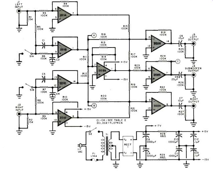
Above: Fig. 1. Schematic diagram.
=============
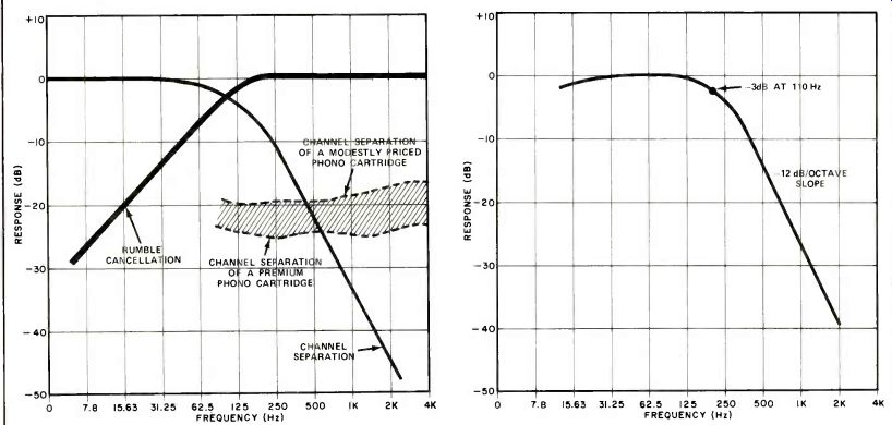
Fig. 2. Performance curves for low-pass-filter cutoff frequency of 220
Hz. Heavy curve shows the extent to which difference information is suppressed
as a function of frequency.
Fig. 3. Low-pass-filter response that characterizes the subwoofer-output channel. Stereo-output channels have a complementary, high-pass characteristic.
The performance of the project in the rumble-suppressing mode is summarized by the graphs of Fig. 2.
The heavy curve shows the extent to which low-frequency difference information is cancelled when the low-pass filters have cutoff frequencies of 220 Hz. The lighter-weight curve shows the extent to which channel separation is maintained as a function of frequency. Two dashed curves show the measured separation available from modestly priced and premium phono cartridges. These latter curves demonstrate that, above bass frequencies, the project does not adversely affect realizable separation.
A monaural signal that can be used to drive a subwoofer power amplifier is available at the output of IC2C. This filtered and summed bass signal is in phase with respect to the bass components of the stereo input signals. However, in this application, resistors R17 and R19 must be deleted so that the summed bass is not also present in the stereo outputs. Accordingly, the stereo system handles only the upper bass, midrange, and high frequencies, Figure 3 shows the lowpass-filter response that characterizes the output presented at J4 for a cutoff frequency of 110 Hz. The stereo out-puts presented at J3 and J5 have complementary (high-pass) responses.
For those who want reassurance that difference information cancelled along with the rumble is audibly insignificant, an unusual, dynamic separation indicator is presented as an option. It responds primarily to the frequencies affected by the bass-summing process, and is shown schematically in Fig. 4. The design of this indicator is based on the fact that separation is reflected as an increase in the level of difference information relative to the level of in-phase information. Differential amplifier IC3A processes the filtered right- and left-channel bass signals to obtain difference information. The output of IC3A is rectified by IC3B and D1, and charges C18.
Summed bass is available at the output of IC2C (point C in Fig. 1). It is brought up to an equivalent level by amplifier IC3C. The frequency response of this stage is shaped by capacitors C21 and C22 to attenuate the unwanted higher frequencies. The amplified, summed bass output of IC3C is rectified by IC3D and D2, and charges C19.
Comparators IC4A, IC4B, and IC4C compare the two resulting dc levels and light LED3, LED2, and LED1 at progressively higher levels of separation. The network comprising D3, D4, R43 and R44 maintains a small bias voltage across C19. This prevents random triggering of the comparators by noise at low signal levels. Such triggering would otherwise be troublesome because signal comparison is based on ratios, not fixed voltage levels.
Options and Modifications. Before undertaking construction, you should determine exactly what function(s) you want this project to perform. If you want only to suppress rumble, you will probably want a filter cutoff frequency of 220 Hz (330 Hz if the rumble is severe). Table I shows which values of capacitors and resistors to use for these frequencies.
Also listed are component values for a cutoff frequency of 110 Hz, which is a better choice if a subwoofer is used. In a Bass Summing Amplifier to be used for rumble reduction only, there are a few components which can be eliminated (C6, J4, and R26). To drive a subwoofer power amplifier in addition, however, two resistors (R17 and R19) must be deleted. Whether the project is used for both purposes or only for rumble suppression, you have the option of including the separation indicator. If you choose not to include it, some parts can be deleted.
They are denoted by an asterisk in the Parts List.
TABLE I---VALUES OF FILTER COMPONENTS FOR SELECTED CUTOFF (-3-dB) FREQUENCIES
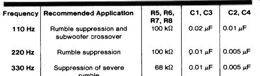
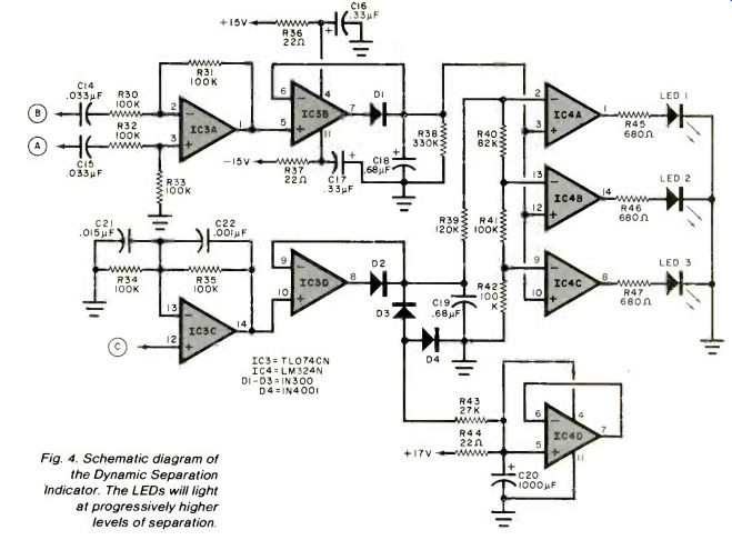
Fig. 4. Schematic diagram of the Dynamic Separation Indicator. The LEDs will light at progressively higher levels of separation.
Construction. There are no high-gain or other stages in which circuit layout is critical. However, the use of a printed-circuit board is recommended because of the rather high parts count. The full-size etching and drilling guide for a suitable pc board appears in Fig. 5. Its corresponding component placement guide appears in Fig. 6. The use of IC sockets or Molex Soldercons is recommended.
There are a few points to consider concerning component selection. To minimize distortion, the capacitors in the low-pass filters (C1 through C4) should be metallized plastic-film or other high-quality components. For the same reason, C5, C6, and C7 should be nonpolarized electrolytics.
Purists will also want to connect 0.1uF metallized plastic-film capacitors in parallel with C5, C6, and C7.
Carbon-film, 5%-tolerance resistors are acceptable for use in this project, but a simple pre-selection procedure requiring only an ohmmeter is recommended. The ohmmeter need not be particularly accurate, but should allow you to resolve slight differences in resistance around a center value of 100 kilohms. Exact values are not as important as close matches.
First, measure the values of some 100-kilohm resistors and set aside four that match very closely for R15 through R18. Select another matching group of four as R19 through R22.
Select a third group of four as R1 through R14. Finally, select two closely matched pairs, one pair for R3 and R4, the other for R9 and R10. The project will perform reasonably well even if this process is not followed, but the more closely matched in value the members of a given group, and the closer the tolerances of C1 through C4, the smoother the frequency response.
When mounting the components on the printed-circuit board, take note of device orientation and the presence of the two short jumpers at pins 5 and 10 of IC1. Also note that R1 and R2 are soldered across each of the input jacks--they are not mounted on the board. Similarly, R25, R26, and R27 are soldered across the appropriate output jacks. The project should be housed in a metal enclosure with shielded cable connecting the pc board to the input and output jacks and switch S1. Testing. Double check the circuit assembly. Then apply power and verify that the positive and negative supply voltages are equal and less than 18 volts. A one-volt, 30-Hz signal applied to J1, the LEFT INPUT jack, should result in the appearance of half-volt signals at both J3 and J5, the LEFT and RIGHT OUTPUT jacks. If the project has been built for subwoofer use, the half-volt signal should appear at J4, the SUBWOOFER OUTPUT jack, only. If a 30-Hz, one-volt signal is applied to J1 and J2 simultaneously, the outputs at J3 and J5 or the output at J4 should increase to one volt.
If you have built the dynamic separation indicator, you can test its operation by applying a 30-Hz signal.
When the input signal is applied to either JI or J2 (but not both), all three LED's should glow. Ideally, they should all extinguish when both channels are driven by the same input signal. Check to see if this happens.
Next, change the frequency of the test signal to 3000 Hz but keep its amplitude at one volt. Apply this signal to J1. A one-volt signal should now appear only at J3. Then apply the signal to J2 and verify that an output appears only at J5. At this frequency, none of the LEDs should glow, even if only one channel is driven. If LED3 does glow, decrease the level of the input signal to see if it extinguishes.
(These statements assume, of course, that S1 is open.) If you don't have access to test equipment, you can patch the project into your system at a line-level point in the signal chain. The Bass Summing Amplifier should be connected after any signal-processing components such as an equalizer, a dynamic-range expander, etc. Then find a quiet groove on a vinyl disc and play it. Listen for rumble, and open and close switch SI. A difference in the rumble level should be noticeable. During such a test, LED3 might flicker, but the other two LEDs should flash only very rarely.
-----------
AUTHOR'S SPECIFICATIONS
Input Impedance: 10 K-ohm
Recommended Load Impedance: 10 k-ohm or greater Input-signal Level: 0.3 to 3.0 volts rms; 1.0 volt recommended
Total Distortion: Less than 0.05%
S/N: Better than 70 dB (unweighted)
Frequency Response: 50 Hz to 16 kHz ± 1/4 dB at stereo outputs with R17 and R19 in project; filter resistors preselected according to procedure described in text; both channels driven, S1 open.
------------------
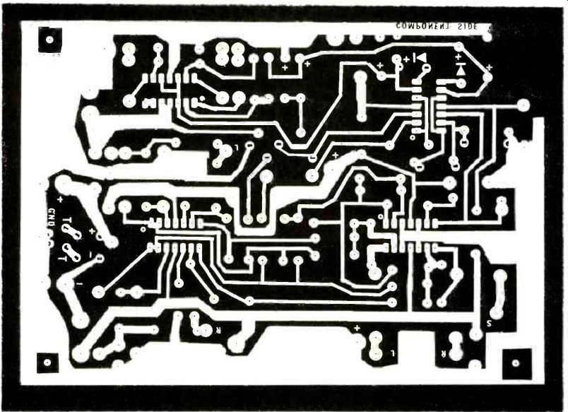
Fig. 5. Full-size etching and drilling guide (above) for the Bass Summing
Amplifier and Dynamic Separation Indicator.
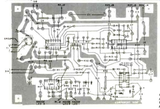
Fig. 6. Component placement guide to be used with the printed-circuit
board.
Use. For the Bass Summing Amplifier to function properly, your audio system needs to be well balanced at the point at which signals are routed to the inputs of the Bass Summing Amplifier. Use the monaurally recorded bands of a test record, or listen to a quiet groove of a standard disc while adjusting interchannel balance.
Maximum cancellation occurs when the channels are exactly balanced.
Even high-quality phono cartridges have some imbalance, and as much as 2 dB will degrade the rumble-cancelling capability of the project.
The net result of your efforts will be quieter and more satisfying bass. As a bonus, the bass summing amplifier can be used to reduce rumble on tapes that have been dubbed from noisy turntables or from FM broadcasts generated using outdated studio equipment.
Source: Computers and Electronics--Experimenter's Handbook (1984)
Also see:
How Many Hours are on Your PHONO STYLUS?