BY DENNIS BOHN
ALMOST every hi-fi phono stylus is made from the hardest substance known to man-diamond. Even a diamond stylus, however, will become appreciably worn after a given number of hours of use. Keeping track of the number of playing hours a stylus has accumulated-and thus indirectly the degree to which it has become worn-is important for two reasons. Using a worn phono stylus dramatically reduces playback fidelity and can cause catastrophic, permanent physical damage to the grooves of a vinyl recording.
Presented here is a simple, inexpensive project that logs the number of hours a stylus has been used. This information is displayed at the push of a button on a four-digit, seven-segment LED readout to the nearest tenth of an hour.
The low construction cost of this project--$50 or less--makes it an ideal solution to the problem of monitoring stylus use. With it, you will eliminate both the risk of using the same stylus too long and the needless expense of replacing it too soon.
About the Project. One principal design goal was to produce a circuit that would provide as accurate a count of actual stylus playing time as possible.
This immediately ruled out the use of any scheme involving the sensing of the amount of time that the turntable was simply on. What was required was a method of determining the amount of time that the cartridge would actually be generating an audio output for subsequent processing by the phono preamp.
This is the approach that was taken in the project described here.
The project is shown schematically in Fig. 1. Because there is no easy access to the output of the phono-preamp stage (apart from the fact that most equipment warrantees would be voided by any such tampering), the stylus timer begins with its own RIAA phono preamplifier.
The audio output of one of the cartridge's channels is tapped at the stereo system's phono-preamp input by means of a Y connector/adapter and a short patch cord. Sensing the input signal of only one audio channel was deemed sufficient for the accuracy required. It is highly unlikely that long periods of time will exist in which there is a total absence of signal in one channel of a typical stereo disc.
The output of the phono cartridge is applied to AUDIO INPUT jack J1. One megohm of resistance (R1) and 20 pF or less of parasitic shunt capacitance comprise the input impedance of the project.
This means that there is no additional, significant loading of the cartridge.
Therefore, the stylus timer's input network does not appreciably alter the loading and hence sonic performance of the phono cartridge.
Operational amplifier IC1 boosts the level of the input signal and, with the help of R2, R3, C2 and C3, provides RIAA playback equalization. Because the op amp is powered by a single-ended supply, do level-shifting of the input signal (performed by C5, R5 and R6) and capacitive input coupling (furnished by C1) are required. Output signals from IC1 are directly coupled to the noninverting input of IC2D, which is one fourth of an LM339 quad comparator.
This stage is operated in linear fashion as an op amp with transistor QI inside the overall feedback loop. Resistors R10 and R11 determine the bias of Q1. Resistor R7 and capacitors C6, C7 and C9 furnish frequency compensation to ensure stability.
The 20 dB of gain provided by IC2D and the 40 dB of gain supplied by IC1 (at 1 kHz) boost the input signal to the level required by the half-wave rectifying and averaging network D4, C11, and R13. The amplified input signal is converted into a positive dc voltage appearing across capacitor C11, which charges rapidly and discharges slowly through R13.
Comparator IC2C accepts the dc voltage appearing across C11 and compares it with the reference of approximately 100 mV generated by R17, R18 and C12. Resistors R14 and R15 provide hysteresis to stabilize the comparator.
The output of this comparator is applied to the noninverting input of comparator IC2B, while the inverting input receives a shaped timebase signal derived from the ac power line. Transformer T1 supplies a low-voltage 60-Hz sine wave to low-pass filter R19C13, whose output is attenuated by voltage divider R20R23.
The attenuated sine wave, converted into a square wave with a dc offset by IC2A, is applied to the inverting input of comparator IC2B.
=============
PARTS LIST
B1--4.2-V mercury battery (Mallory No. TR-133 or equivalent)
C1--0.0033-uF Mylar capacitor
C2--0.0027-uF Mylar capacitor
C3--0.01-µF Mylar capacitor
C4,C8,C10--10-µF, 6.3-V tantalum capacitor
C5,C11,C12-100-µF, 10-V, radial-lead electrolytic capacitor
C6--0.1-µF disc capacitor
C7--0.001-µF Mylar capacitor
C9--0.005-µF disc capacitor
C13-0.01-µF disc capacitor
C14-100-µF, 35-V, radial-lead electrolytic capacitor
C15-330-µF, 6.3-V tantalum capacitor (see text)
C16--56-pF disc capacitor
D1,D2--1N4001 rectifier diode
D3,D6-1N914 signal diode
D4--1N34 germanium signal diode
D5--1N4736 6.2-V zener diode
D1S1--Four-digit, common-cathode LED display (NSA 1541 or equivalent)
IC1-LM301A operational amplifier
IC2-LM339 quad comparator
IC3-CD4013 dual D flip-flop
IC4-CD4059 programmable divide-by-n counter
IC5-MM74C925 four-decade counter with multiplexed four-digit, seven segment output drivers
J1-Insulated phono jack
Q1 through Q5-2N5210 or equivalent npn silicon transistor
Q6-2N5086 or equivalent pnp silicon transistor
The following, unless otherwise specified, are 1/4-watt, 10%, fixed carbon-composition resistors:
R1, R15, R22--1 megohm
R2,R23-27,000 ohms
R3-470,000 ohms
R4-330 ohms
R 5, R 6, R 12, R 16, R 19, R 26-100, 000 ohms
R7-10 ohms
R8,R14,R21,R27 through R33-1000 ohms
R9,R11,R13-10,000 ohms
R10-15,000 ohms
R17,R36-6800 ohms
R18-100 ohms
R20 33,000 ohms
R24, R25, R37-3300 ohms
R35-330-ohm, 1/2-watt resistor
S1,S2--Normally-open, momentary-contact pushbutton switch
T1-24-volt center-tapped, 40-mA stepdown transformer
Misc.-Printed circuit board; IC sockets or Molex Soldercons; battery holder; fuse holder; suitable enclosure; Y phono-connector/adapter; shielded cable; phono plugs; hookup wire; line cord and strain relief; suitable hardware; solder; etc.
Note: The following are available from TOLECO Systems, Box 401, Kingston, WA 98346: kit of parts consisting of all required integrated circuits, common-cathode LED display, and etched, drilled, and plated glass-epoxy printed circuit board, No. ST-1, for $34.95 plus $2.00 postage and handling in the U.S. and Canada, $4.00 all other countries; etched, drilled, and plated glass-epoxy printed circuit board, No. ST-2, for $10.00 postpaid in U.S. Washington residents, add 8% sales tax. No COD or foreign-currency orders. As designed, the project is suitable for use only in those areas where power-line frequency is 60 Hz.
------------
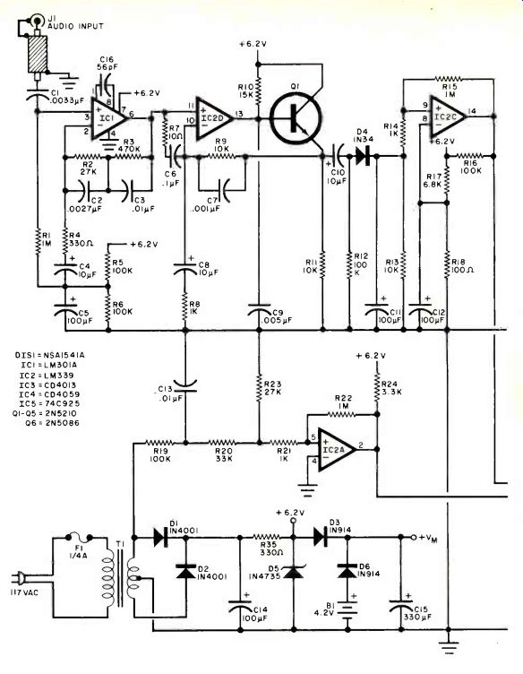
------- Fig. 1. The audio input is obtained from one channel of the cartridge output to the phone preamp. it is then amplified and rectified and compared to a reference to create timed pulses and drive the digital display.
============
This comparator passes timebase pulses when audio from the cartridge drives the output of IC2C high. Time-base pulses then reach the CLOCK input of the first section of dual D flip-flop IC3. The mismatch between pull-up resistors R16 and R24 holds the output of IC2B low in the absence of a signal from the cartridge.
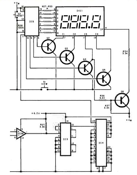
The timebase signal from IC2B passes to dual D flip-flop IC3, which functions as a divide-by-4 counter. A 15-Hz pulse train appears at the Q output of the second flip-flop in IC3 (pin 13) when IC2B allows the clock signal to pass. This pulse train is applied to the input of IC4, which is programmed to divide the input frequency by 5400. The resulting output pulse train has a period of 6 minutes or 0.1 hour and appears at pin 23 of IC4 to clock four-decade counter IC5.
This chip contains not only counting stages but also seven-segment decoders and multiplexed display drivers. The outputs of IC5 drive not only the seven segment lines of D1S1 but transistors Q2 through Q6 as well. The latter drive the digit and decimal-point cathode lines of the display. Their emitters are connected together and to one side of pushbutton VIEW switch S1, the other side of which is grounded. No current flows through the LED display until the VIEW switch is closed. The elapsed stylus playing time is indicated in hundreds, tens, units, and tenths of an hour up to 999.9 hours. When 999.9 hours have been tallied, counter IC5 resets to 000.0. The user can manually clear the counter by closing RESET pushbutton switch S2. Resistor R26 is the pull-down component for switch S2.
A simple single-ended, full-wave supply satisfies the project's power requirements. There is no power on/off switch; line power should be applied continuously so that the information stored in IC5 is not lost. One simple way to do this is to plug its line cord into the audio preamplifier's or receiver's unswitched power socket. Mercury battery BI and steering diodes D3 and D6 ensure that the count stored in IC5 is not lost during power failures and during times when it is necessary to unplug the timer from the power line. Current drain of IC5 is low, making battery life at least as long as that of the stylus. It is good practice to replace the battery each time the stylus is replaced. Capacitor C15 is optional and supplies power when both ac and battery power are lost.
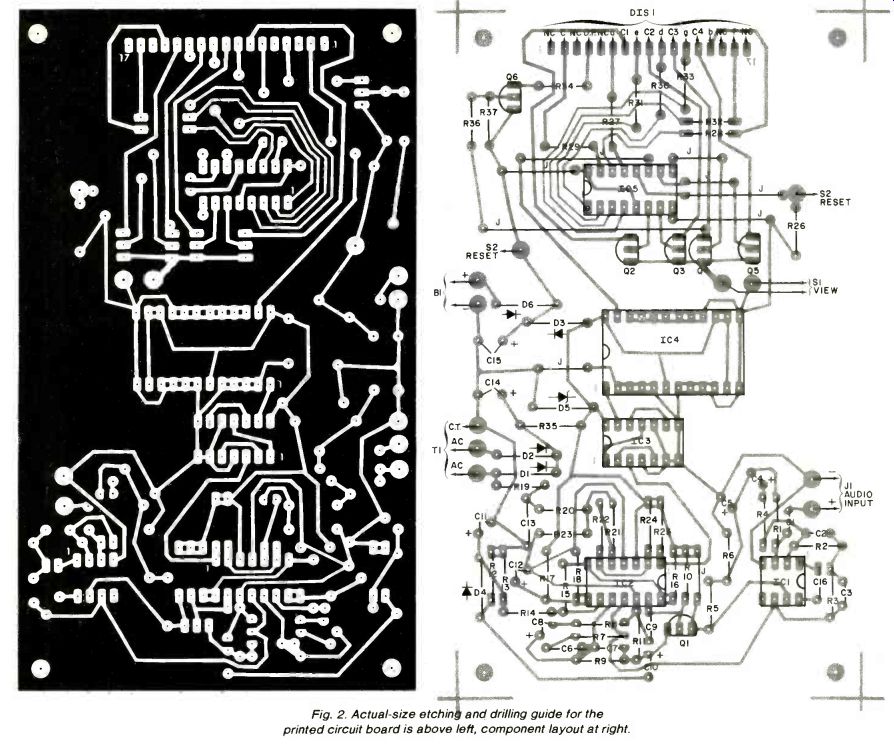
Fig. 2. Actual-size etching and drilling guide for the printed circuit
board is above left, component layout at right.
Construction. The high impedances and gains of the early stages of the signal-processing chain make the use of a carefully designed printed-circuit board almost a necessity. An etching and drilling guide and component layout are shown in Fig. 2. To keep construction cost low, a single-sided pc board using several jumper wires was used. As long as the jumpers are as short as possible and are installed neatly, they need not be insulated.
After the jumpers are in place, install the resistors, and then the diodes-in the correct polarity. Molex Soldercons or IC sockets should be mounted on the board after the diodes, and then the capacitors should be installed. (The polarities of electrolytic capacitors must be observed.) Finally, the transistors should be installed. Using a small-tipped, low-wattage soldering iron and small-diameter (No. 22 AWG or similar), 60/40 rosin-core solder, make all necessary connections.
When all pc components have been mounted on the board, use suitable lengths of shielded cable and hook-up wire to connect the appropriate foil pads to those components that are not mounted on the board. Connect the shield of the cable running between input jack JI and the input foil pads at both ends. However, use an insulated phono jack to prevent a ground loop from arising. A suitable length of multi-conductor ribbon cable can be used between the pc board and the display.
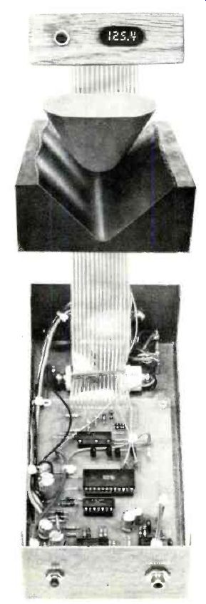
The author's prototype is housed in an aluminum utility box that encloses everything except the LED display and the VIEW switch. These were mounted on a small piece of oak and interconnected with the boxed section by a length of multiconductor ribbon cable. This arrangement permitted the placement of the utility box behind the audio preamplifier and the attachment of the oak display board to the rear of the turntable. The RESET switch was mounted inside the enclosure to prevent accidental switch closure and loss of count.
The display used by the author is a four-digit calculator-type readout selected for small size and low current demand. However, almost any type of LED display can be used, so long as it is of common-cathode design and is compatible with multiplexing. Discrete-digit LED readouts can be used in this application if all pins corresponding to the same display segment (a, b, c, etc.) are connected together to the appropriate outputs of ICS. Any available display color is acceptable. However, the use of a LED readout other than the one specified might require a change in value of current-limiting resistors R27 through R33. Increasing the resistances will result in diminished display current and brightness. Decreasing them will cause more current to flow and more light to be radiated by the display segments.
The output drivers of ICS can source a maximum of 30 mA, so the lower limit of resistance for R27 through R33 is approximately 100 ohms.
Transformer TI as specified is a 24-volt center-tapped component with a rated secondary current of 40 mA. The author's prototype has an actual current demand of approximately 32 mA in either the STANDBY (S1 open) or VIEW (S1 closed) mode. In the latter, the flow of display current causes a decrease in current flow through zener diode D5.
This is why the overall current demand remains constant whether the readout is glowing or not. If a display requiring more current is used, T1 will have to be a component that can deliver more secondary current.
In any event, to minimize hum pickup and possible false time counts, the transformer should be positioned as far away from the input stage as possible. Its leads should be routed along the opposite side of the pc board from the input cable or, even better, at the opposite side of the board and at right angles to the input cable.
Installation and Use. For initial checkout, plug the line cord into an ac power socket and depress the VIEW pushbutton switch. The display should read 000.0. If it indicates some other number, momentarily close the RESET switch and verify that the display returns to 000.0 when the VIEW switch is closed again.
Next, position the project near your turntable and preamplifier in such a way that the LED display can easily be seen. Make sure that the audio system is turned off. Then disconnect one of the signal cables running from the turntable to the PHONO input jacks of the system's preamplifier. Either the right- or left-channel output of the turntable can be used. Connect a suitable Y adapter to the unoccupied preamplifier PHONO input jack and plug the floating output cable from the turntable into one of the adapter's two phono jacks. Finally, connect one end of a patch cord to the remaining Y-adapter phono jack, and the other end of the patch cord to the project's audio input jack (J1). Turn the stereo system on and play a record for slightly more than six minutes, verifying that the display reads 000.1 hour when the VIEW switch is closed. If it does, return the tonearm to its rest position and unplug the project's line cord from the power socket. Wait a few minutes and reconnect the project to the ac power source. Depress the VIEW pushbutton switch once more. A readout of 000.1 hour on the LED display confirms that the battery-powered memory-backup circuit is working.
Finally, apply ac power to the stylus timer and to the audio system. Place the preamp’s positioners selector switch to PHONO mode , leaving the tonearm switch in its rest position. At the end of an hour, press of VIEW pushbutton switch. If the display still reads an elapsed time off 000.1 hour, the project is not falsely counting the 60-Hz power-line frequency. If a false count is indicated, reroute any ac line cords passing near the project's audio input jack. Also, check the audio cable-s shield and the connections between the shield and phono jacks. Grounding the metal enclosure to the audio system's ground at only one point will also help keep 60-Hz ac out of the high-gain stages of the timer. Repeat the test procedure to ensure that the false-count problem has been solved.
Knowing the playing time of the stylus to the nearest hour or even ten hours is sufficient for replacement purposes. Contact the manufacturer of your cartridge for the recommended stylus replacement interval. If this information is not available, check spherical styli after about 200 hours, elliptical styli after 500 hours, and Shibata and similar styli after 900 hours.
Use a stylus microscope for making visual inspections. If in double about replacement, consult a dealer.
Source: Computers and Electronics--Experimenter's Handbook (1984)
Also see:
Cancel Rumble With This Bass-Summing Amplifier