AMAZON multi-meters discounts AMAZON oscilloscope discounts
Half-wave rectifier circuits are very common in power sup plies of electronic equipment. This is especially true where low cost and high output voltage are essential. In this section, the following circuits will be discussed: Half-wave transformerless rectifier.
Half-wave voltage-doubler rectifier.
Half-wave rectifier with transformer.
TRANSFORMERLESS HALF-WAVE RECTIFIER
Fig. 2-1 and 2-2 show two successive half-cycles in the operation of a
transformerless half-wave rectifier power supply. This type of power supply
may be plugged directly into either an alternating- or direct-current power
line. Because of this feature, the power supply is known as an AC-DC supply.
(Obviously, when the unit is operated from a DC line, there will be no
such thing as an alternating half-cycle.) The essential components of this
power supply are:
R1-Filter resistor.
R2-Voltage-divider resistor for taking output voltages.
C1-First filter capacitor.
C2-Second filter capacitor.
C3-Isolating capacitor.
V1-Half-wave rectifier tube.
Only two main types of currents are at work in this circuit.
They are:
1. Main rectifier current (red).
2. Filter currents (green).
When the applied power-line voltage makes the plate of the rectifier tube more positive than the cathode, the tube will con-duct electrons from cathode to plate. Their path starts at the other side of the power line. These electrons flow upward through voltage-divider resistor R2, and then to the left through filter resistor R1, en route to the cathode.
Resistor R1 and capacitor C1 form a long time-constant filter of the type discussed in the introductory section to the oscillator volume in this series. Resistor R2 and capacitor C2 form another long time-constant filter combination. These two RC combinations provide adequate filtering and consequently adequate reduction in ripple voltage.
When the circuit is turned off and is at rest, zero output voltage will be measured at either output point. However, as soon as power is applied, electrons will leave the cathode during each positive half-cycle and cross to the plate of the rectifier tube.
This action leaves the cathode with a deficiency of electrons and consequently with a positive voltage. The upper plate of capacitor C1 immediately assumes this value of positive voltage.
The only way this positive voltage can be reduced to zero is by drawing electrons up from the other side of the line, through the two resistors. (This current is shown in red.) Because these are long time-constant filters, the positive cathode voltage under goes only insignificant reduction before the next positive half cycle of power-line voltage is applied. Each positive half-cycle draws more electrons across the tube. During negative half cycles like those represented in Fig. 2-2, no electrons cross the tube. However, the upward flow of electrons through the resistor path continues throughout the entire cycle.
Ohm's law tells us that the voltage across a resistor is proportionate to the current through it. This is written symbolically as: E=IxR where,
E is the voltage in volts,
I is the current in amperes,
R is the resistance in ohms.
Coulomb's law tells us that the amount of voltage across a charged capacitor is proportionate to the quantity of electrons (or positive ions) stored there. This is written symbolically as:
Q=CxE
where,
Q is the number of coulombs of charge stored (1 coulomb = 6.25 X 10^18 electrons),
C is the size of the capacitor in farads,
E is the voltage across the capacitor in volts.
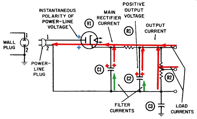
Fig. 2-1. Operation of the transformerless half-wave rectifier conducting
half-cycle.
This formula can be rewritten as: E=Q C
Since the voltage across capacitor C2 is identical to the output voltage across R2, we can make these voltage equations equal to each other and say: where, Q C2=1XR2 Q is the quantity of positive ions stored on the upper plate of C2, I is the main rectifier current (in red) flowing upward through R2.
The positive voltage on the upper plate of C1 draws electrons to the left, through resistor R1. The deficiency of electrons created on the upper plate of C2 becomes the output voltage. It is this positive voltage that draws electron current upward through voltage-divider resistor R2. Any fraction of the total output voltage can be obtained by placing an appropriate tap on the voltage divider.
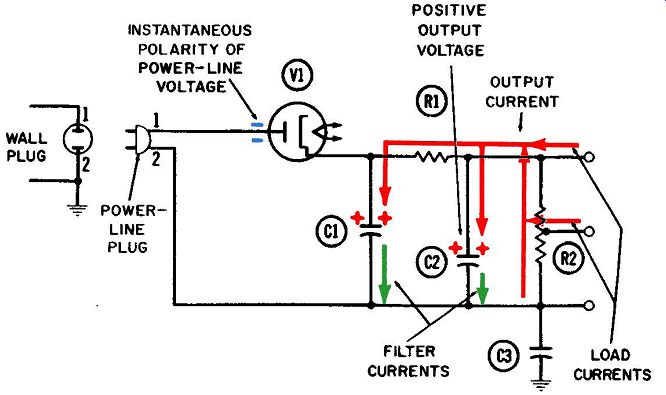
Fig. 2-2. Operation of the transformerless half-wave rectifier nonconducting
half-cycle.
Filter Currents:
The RC filtering used in this power supply is identical in principle to the cathode filtering discussed in the oscillator and amplifier volumes of this series. As electrons are drawn into the rectifier tube, they can come from one of two places--either directly through the high-impedance path composed of R1 and R2, or from the upper plate of C1 (which offers a much lower impedance). Naturally, most of the tube-current electrons come from the top of capacitor C1. In order for this to happen, an equal number must be able to flow onto the capacitor's lower plate. These are the electrons, shown in green, flowing upward into C1 during the first half-cycle (Fig. 2-1). On the negative half-cycle such as are shown in Fig. 2-2, these electrons flow back down to the other side of the line. These two movements constitute the filter action of the capacitor.
A similar filter current flows between the lower plate of C2 and the neutral side of the line. This filter current is much smaller because C1 has already filtered out most of the fluctuation in the main rectifier current.
Capacitor C3 isolates the equipment from ground to eliminate the danger of shock. As shown in Figs. 2-1 and 2-2, the two leads on the left connect to the two prongs of an ordinary electric plug.
One of the two wires leading to the wall outlet in the home is normally grounded and the other is "hot." Capacitor C3 could be omitted and the lower end of R2 grounded directly, provided one could always be sure prong 2 would be plugged into the ground side of the power line and prong number 1 into the "hot" side. However, since the plug can be inserted either way, the user runs the risk of connecting the "hot" side of the line directly to the receiver ground, which is usually the chassis. This could result in a dangerous shock, so C3 is added between the line and the receiver chassis as a safeguard.
TRANSFORMER INPUT HALF-WAVE RECTIFIER
Figs. 2-3 and 2-4 show two successive half-cycles in the operation of a half-wave rectifier power supply using a step-up input power transformer. The filter circuit used for converting the resultant pulsating DC into pure DC is similar to the previous circuit used with the transformerless power supply. Both use a resistor ( R1) instead of the bulkier and more costly filter choke.
Another disadvantage of a filter choke is that the continual pas sage of current in a single direction through the winding establishes a permanent magnetic field. This feature can be seen more clearly in the next section, where the full-wave rectifier is discussed. However, using a resistor in lieu of a filter choke is not without its disadvantage. There is a definite voltage drop and power loss, occasioned by the flow of all the rectified current through the resistor. This loss in voltage and power is in addition to the power consumed by the rectifier current flowing upward through output resistor R2.
Circuit Components This circuit is made up of the following components: R1-Filter resistor.
R2-Output resistor, suitably tapped to provide any desired partial voltages.
C1-Input filter capacitor.
C2-Output filter capacitor.
T1-Power transformer.
V1-Diode tube.
Identification of Currents
The following currents are at work in this type of circuit:
1. Power-transformer primary current (solid blue).
2. Power-transformer secondary current ( also in solid blue) .
3. Diode tube current (red).
4. Cathode heating current (dotted blue).
5. 60-cycle filter currents (green).
Fig. 2-3 shows the half-cycle when the power transformer makes the diode plate positive, so that electrons can cross the tube. An attempt has been made to depict this transformer action just as it actually occurs in these figures. The current in the primary, which is the driving current, can be considered to flow downward through the primary in the first half-cycle, in response to an applied negative voltage. This applied polarity has been indicated by the minus sign at the top of the primary winding.
This primary current induces a voltage in the secondary winding which is in opposition to the applied voltage. The polarity of this "back emf" has been indicated by the plus sign at the top of the secondary current associated with this induced voltage, and its flow direction is indicated as upward during the first half-cycle.
This induced voltage and current will have their greatest values twice during each cycle, when the primary inducing current is changing at the maximum rate. While the primary inducing current has its greatest value, the secondary induced current and voltage will be zero. These moments also occur twice during each cycle-midway in each half-cycle.
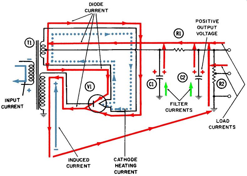
Fig. 2-3. The transformer input half-wave rectifier-first half-cycle.
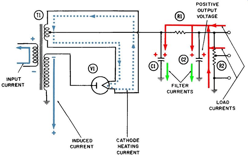
Fig. 2-4. The transformer input half-wave rectifier-second half-cycle.
Heating Current
The power transformer used here and in most power-supply applications has a third, or tertiary, winding which delivers a large flow of current to heat the filament or cathode, in order that emission may occur. This current, shown in dotted blue, follows the closed path through the winding and through the filament or cathode. The example used here is a directly heated cathode which requires no additional filament.. This heating current flows at the same frequency as the power current, which is 60 cycles per second in most parts of the United States. It is shown flowing clockwise during the first half-cycle and counterclockwise during the second. The wire connecting the filter network to the cathode is usually brought to the center tap of this winding. In this way, a minimum of 60-cycle ripple (due to the heating operation) will be coupled into the filter system.
During that portion of the first half-cycle while tube current is flowing, it enters the cathode network through this center tap and flows through both sides of the line to the cathode before entering the tube. Neither of these two currents in the tertiary winding and in the cathode "disturbs" the other one in any sense.
The tertiary winding constitutes a voltage step-down and current step-up device. Tube cathodes and heating filaments are de signed for a certain applied voltage, which varies in size depending on the application. Common values are 5, 6.3, and 12.6 volts.
However, 25- and even 35-volt heaters are used.
The amount of current is of course regulated by the amount of resistance in the winding and that portion of the cathode or filament through which the heating current must flow. The tube is designed so that its current heats the cathode sufficiently to emit electrons without burning up the tube.
Sometimes the lead from the filter circuit is connected directly to one side of the filament. Operation is the same, except the diode current flows from the filter circuit directly to the filament, and through the tube to the transformer. In other versions, a tube with an indirectly heated cathode is employed. Then the filter circuit is connected to the cathode and the heater is entirely in dependent.
Filter Currents
The filter network here operates on the same principle de scribed for the preceding transformerless power supply. As the electron current leaves the cathode and flows across the tube, these filter currents (in green) flow upward from ground into filter capacitors C1 and C2. When the electron flow across the tube stops during the second half-cycle, these filter currents flow downward to ground.
VOLTAGE DOUBLER
Figs. 2-5 and 2-6 show two successive half-cycles in the operation of a dual-diode rectifier system being used as a voltage doubler. This particular circuit includes a step-up input trans former. However, it is even more common for the voltage doubling principle to be used with a transformerless input. The output voltage would then be limited to about 2.8 times the peak value of the alternating supply voltage. With a step-up trans former, the maximum output voltage attainable will equal this figure, multiplied by the turns ratio of the transformer.
As an example, if the input voltage is the standard 110 volts ( effective value) , its peak value will be 1.4 times as great, or about 155 volts. When doubled, this would come to 310 volts; this is the maximum attainable in a transformerless circuit. In the circuit shown in Figs. 2-5 and 2-6, if the transformer turns ratio were 2-to-1, then the maximum attainable output voltage would be twice as much, or 620 volts.
The following circuit components make up this voltage doubling circuit:
R2-Output resistor.
C1-Output capacitor.
C2-Output capacitor.
T1-Power transformer.
V1 and V2-Diode tubes.
Identification of Currents
The following electron currents are at work in a circuit of this type:
1. Input power current (blue) .
2. Current through V1 (solid red).
3. Current through V2 ( dotted red).
Details of Operation:
The plate of diode V1 and the cathode of diode V2 are connected directly together and also to the top of the transformer secondary winding. In the first half-cycle shown in Fig. 2-5, trans former action makes the top of this winding positive. V1 conducts from cathode to plate. V2 is of course unable to conduct, since its cathode is more positive than its plate.
The flow of electrons from cathode to plate of V1 charges the upper plate of capacitor C1 to a positive voltage which is almost equal to the peak transformer secondary voltage. The reason is that the capacitor gives up electrons to provide the necessary tube current; the resultant electron deficiency constitutes a positive voltage. As a result of this current flow through the diode and the positively charged capacitor, electron current is drawn upward through resistor R2. This is part of the output current of the rectifier, and it has been shown in solid red lines. The voltage it will develop across R2 will always be proportionate to the amount of current flowing, in accordance with Ohm's law, and will always be exactly equal to the voltage across capacitor C1.
After passing from cathode to plate, these electrons head down ward through the transformer secondary winding and enter the neutral, or ground, point between the two capacitors.
During the second half-cycle, shown in Fig. 2-6, transformer action causes the top of the secondary winding to assume a negative voltage. This negative voltage appears at the plate of V1 and prevents any electron current from flowing through this tube.
However, the same negative voltage at the cathode of V2 causes a full flow of electrons across this tube. These electrons originate at the ground point between the two capacitors and flow upward through the secondary winding, then downward to the cathode of V2 and through the tube to the lower plate of capacitor C2. Here they accumulate, forming a negative voltage almost equal in value to the negative peak value of the induced voltage across the secondary winding. This negative charge on the lower plate of C2 drives a continuous electron current upward through resistor R2.
This current, shown in dotted red lines, is also part of the rectifier output current. It develops a voltage across R2 that will at all times be exactly equal to the negative voltage existing across capacitor C2.
Consequently, these two currents flowing upward simultaneously through R2 will develop a voltage across it which is approximately twice as great as either current could develop alone.
The total voltage across R2 is of course equal to the sum of the two capacitor voltages, and almost equal to twice the peak secondary voltage. Because of this feature, the circuit is referred to as a voltage-doubler circuit.
ADVANTAGE OF HALF-WAVE OPERATION
The principal advantage of using a half- rather than full-wave power supply (discussed in the next section) is that a power transformer is unnecessary. However, when a power transformer is used, a higher output voltage can be obtained for a given size and weight of transformer. A higher voltage can be obtained with half-wave operation because the entire amount of secondary voltage is applied to the plate of the rectifier tube. The DC voltage developed at the cathode can never exceed this peak secondary voltage, although the two will usually be very close in value.
If the secondary of this transformer were center tapped, with the two ends of the winding going to the plates of two rectifier tubes or a twin diode tube (as it is in the full-wave rectifier), then only half the available voltage swing would be applied to each plate, and only half as much output voltage would be avail able across the output resistor. This point can be clarified bycom paring the circuit of Figs. 2-3 and 2-4 with those of the next section.
Let us assume the transformers used in two circuits are identical in construction, turns ratio, size, weight, etc., except that one has a center-tapped secondary to allow for full-wave operation.
Let us also assume that turns ratio is 1-to-3 and that the peak voltage swing of the primary power is about 150 volts, which is reasonably close to home supply conditions (110 volts effective value equals 155 volts peak). Under these conditions, the peak secondary voltage will be 450 volts. In the half-wave rectifier of this section, all this voltage will be applied to the diode plate. The resultant cathode voltage will be close to this value, perhaps 420 volts. (The output voltage across R2 will be somewhat less be cause of the voltage dropped or lost as the rectifier current passes through R1.)
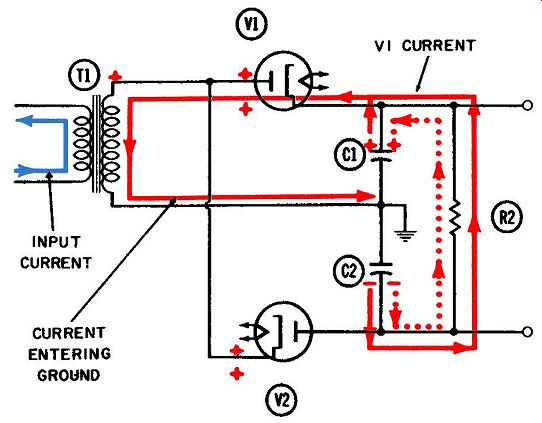
Fig. 2-5. The voltage-doubler rectifier-positive half-cycle.
In the full-wave rectifier, with the center-tap winding connected to ground each plate would be driven alternately between plus and minus 225 volts. The maximum attainable output voltage would thus be limited to 200 volts or so.
Since a transformer is bulky and heavy, there are many applications where its elimination is desirable. For example, most table-model radios use the circuit of Figs. 2-1 and 2-2 and many television receivers employ the voltage-doubler circuit in Figs. 2-5 and 2-6. At other times the circuit of Figs. 2-3 and 2-4 is selected because the advantage of higher output voltage without trans former size or bulk has overriding attractions. An obvious disadvantage which must be accepted in choosing half-wave over full-wave operation is the probability of somewhat poorer voltage regulation.
VOLTAGE REGULATION
Voltage regulation is defined as the percentage variation in output voltage of a power supply in going from no load to full load.
It may be expressed by this formula:
. E-,-E1 Voltage regulation = -E1 X 100 where,
E2 is the output voltage at no load,
El is the output voltage at full load.
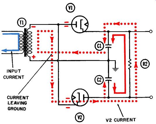
Fig. 2-6. The voltage-doubler rectifier-negative half-cycle.
The no-load condition with a power supply means it is not delivering current to any external circuits. Figs. 2-1 through 2-4 show some load current being drawn toward the rectifier tube from the right side of the diagrams. The electrons which make up this load current are being drawn from all tube circuits supported by this power supply. The power supply delivers current to these load circuits by providing a high positive voltage which draws electrons through them. These electrons are mostly in the form of plate and screen-grid currents of vacuum tubes.
The total current a rectifier tube will draw is determined by its construction and by the applied voltage from the transformer secondary. When little or no load current is flowing, the rectifier will draw all its required current up from ground through resistor R2.
The output voltage is then equal to the voltage developed across R2 by this current, in accordance with Ohm's law.
When substantial load current is drawn, however, the amount of current drawn through R2 will be decreased equally, and the voltage developed across R2 will also be decreased proportionately. This amounts to a reduction in the output voltage under full-load conditions.
Obviously, a voltage regulation of zero percent is unattainable in power supplies of this type. In order for the regulation to equal this ideal, the output voltage under full-load conditions would have to equal the output voltage under no-load conditions-an impossible situation.
In this type of circuit and using RC filters as described, fairly high values of regulation (meaning poor voltage regulation) will be obtained. Values of 30% or 40% are not uncommon.