AMAZON multi-meters discounts AMAZON oscilloscope discounts
In this section, three versions of the full-wave rectifier circuit will be discussed. Half-wave rectifiers, discussed in the previous section, utilize only one half-cycle of the applied alternating voltage. Full-wave rectifiers, on the other hand, use both half-cycles.
This results in a ripple frequency twice that of the half-wave rectifier. In other words, using half-wave rectification the rectifier will conduct for a portion of one half cycle; then, during the next half-cycle, the tube does not conduct. This results in a pulse, then a long period of no voltage, followed by another pulse. Of course, the filter circuit "fills in" between pulses so we have a DC voltage at the output. With the full-wave rectifier, conduction occurs on both half-cycles; hence the output contains twice as many pulses of DC, with no long periods between them. All that is required of the filter circuit is to smooth out the output. Thus, smaller filter capacitors can be employed.
CONVENTIONAL FULL-WAVE RECTIFIER
The first full-wave rectifier circuit to be discussed might be called the "conventional" circuit, which is widely used in power supplies for radios, television sets, etc. It employs a center-tapped transformer, a tube with two diode plates, and a common directly heated cathode. Figs. 3-1 through 3-4 show the four quarter-cycles of operation for the circuit. The components, and their functional titles are:
R1-Load resistor.
C1-First filter capacitor.
C2-Second filter capacitor.
L4-Filter choke.
T1-Power transformer.
V1-Full-wave rectifier tube.
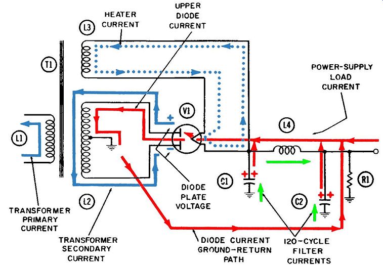
Fig. 3-1. The full-wave rectifier-first quarter-cycle.
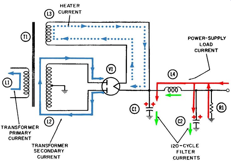
Fig. 3-2. The full-wave rectifier-second quarter-cycle.
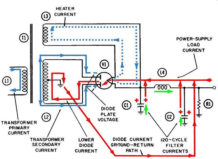
Fig. 3-3. The full-wave rectifier-third quarter-cycle.

Fig. 3-4. The full-wave rectifier-fourth quarter-cycle.
Fig. 3-5 shows the phase relationships between the transformer secondary current, the upper-diode plate voltage, the upper- and lower-diode currents respectively, and finally the output-voltage waveform. (The ripple component of this output voltage has been exaggerated somewhat for easy identification.) No waveform is shown for the lower-diode plate voltage. How ever, such a waveform would be exactly 180°, or half a cycle, out of phase with the upper-diode plate voltage shown in line 2.
It can be seen from these waveforms that each diode conducts once during each cycle and raises the output voltage slightly each time. As a result, the ripple-voltage frequency is twice the basic power frequency. The output-voltage waveform also reveals the fairly abrupt rise in voltage when the diode conducts, as opposed to the much more gradual decay between conduction. This slow decay results from the filtering provided by C1, C2, and L4. This action is explained more fully later in the discussions of the circuit-operation diagrams.
Three separate "families" of currents are shown in Figs. 3-1 through 3-4. The first such family might be called the power group, because all currents are driven from the primary power source such as an AC supply line. There are three currents in this group-transformer primary, transformer secondary, and filament heating.
The second family, or group, of currents is the "rectified," or unidirectional, currents; after being filtered, they enable this circuit to provide the stable DC voltage output necessary for the operation of many electronic systems.
The third family is the filtering current which "smooths" out the pulsations in the rectified current.
Each of these currents is shown in the following colors in Figs. 3-1 through 3-4:
1. Transformer primary current (solid blue).
2. Transformer secondary current (also in solid blue).
3. Tube-filament heating current (dotted blue).
4. Rectified or unidirectional current (red).
5. Filter current (green).
The Power Currents:
The first current of this group flows in the primary winding of the power transformer and is indicated in solid blue. In the aver age household this is a 60-cycle current, and its associated driving voltage is the standard 110 volts. The first quarter-cycle diagram (Fig. 3-1) shows a single quarter-cycle of this driving current as it flows upward through the primary winding. The essential property of a transformer ( or any other inductance) is that it will resist any change in the amount of current flowing at any given moment. During an entire half-cycle (such as the one represented by Figs. 3-1 and 3-2), this primary-winding current undergoes an entire series of changes. Starting from zero, it rises to maximum and falls to zero again, always in the upward direction.
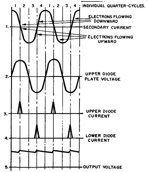
Fig. 3-5. Full-wave rectifier waveforms.
Any changes in direction or amount of this current will cause current movements in other parts of the transformer. The large secondary winding carries a current, also shown in solid blue, whose movements are associated with the voltage changes on the plates of the twin-diode rectifier tube. All currents are electrons in motion. Hence, an electron current flowing in one direction will ultimately deliver a certain quantity of electrons to one end of the current path and will leave a scarcity of them at the other end.
A concentration of free electrons is by definition a negative voltage. By the same token, a scarcity (deficiency) of electrons results in a concentration of positive ions, which is by definition a positive voltage.
During the entire first quarter-cycle, this current moves down ward in the transformer secondary. At the end of the quarter-cycle, the lower end of the transformer has achieved its maximum negative voltage, as depicted by the blue minus sign at the lower plate of the rectifier tube. At the same time, a deficiency of electrons will exist at the upper end of the transformer secondary.
This is shown by the blue plus sign at the plate of the upper rectifier tube.
The upper diode will conduct the maximum amount of rectified (red) current at the same instant this diode plate reaches its maximum positive voltage. The first quarter-cycle diagrams (Figs. 3-1 and 3-5) depict this instant.
The third and final current in this group of power currents flows in the tertiary winding of the transformer. Its purpose is to heat the cathode of the twin-diode rectifier tube. This winding consists of a relatively few turns of wire. Thus it is a low-voltage winding which delivers high current. The current in the primary winding drives this cathode heating current at the same 60-cycle frequency. To clarify the transformer action, this current is shown flowing in opposite phase to its driving current-in other words, downward during the first quarter-cycle and upward during the second and third. During the fourth quarter-cycle, it again flows downward.
This current follows the closed path which includes only the tertiary winding and the direct-heated cathode. In the four diagrams depicting circuit operation (Figs. 3-1 through 3-4), this heating current is shown in dotted blue.
The Rectified Currents:
The rectified currents, in red, eventually flow through the rectifier tubes, from the common cathode to either plate. At the end of the first quarter-cycle, as shown in Figs. 3-1 and 3-5, this current flows from the cathode to the upper plate of the two diodes.
(The current-voltage action in the transformer secondary makes the upper-diode plate positive. This accounts for the electron flow across the tube to the upper-diode plate. Whenever either diode plate is more positive than the cathode, electrons will leave the cathode and cross the open space to that plate.) Any electrons leaving the cathode must be provided with a return path to the cathode. This is a fundamental requirement of vacuum-tube operation. The return path in the circuit of Fig. 3-1 is from the upper plate of the diode to the top of the transformer secondary, then through its upper half to the center tap. Here the current enters a common ground and returns to the bottom of R1. which serves as both a bleeder and a load.
The current then continues upward through R1, then to the left through the filtering inductance, to the cathode.
The diagrams for the third quarter-cycle (Figs. 3-3 and 3-5) show electron current flowing from the cathode to the lower plate of the diode. Current flows in this direction through the tube be cause the secondary current in the transformer has made the lower-diode plate positive. This is indicated by the blue plus sign on the lower plate of the twin-diode tube.
After crossing the lower diode, the rectified current (still shown in red) goes to ground through the lower half of the trans former secondary, then through ground and back to the load resistor. It returns to the cathode by flowing upward through this resistor, and to the left through the filtering inductance L4.
Another component of rectified current is shown entering the filtering inductance from the right. This portion does not pass through the load resistor. Instead, it comes from those vacuum tube circuits which receive their DC power from this rectifier circuit. Once it enters the rectifier, this current follows the same paths as the other through the diodes and transformer secondary to the common ground. From here, it then has a free return path to the cathodes of the other tubes.
An important measure of any rectifier's performance is its capability for voltage regulation-that is, the stability of its output voltage under varying loads. The output voltage of this rectifier is the positive voltage on the upper plate of capacitor C2, and consequently at the output terminal. This voltage, represented by red plus signs, should be as steady as possible under all circum stances from no load to full load-in other words, it should be "regulated," or have "regulation." In any charged capacitor (such as C2), there is a definite relationship between the amount of charge ( electrons or positive ions) stored there and the amount of negative or positive voltage produced. Coulomb's law states this relationship as a formula: Q=CXE where, Q is the quantity of charge in coulombs, C is the size of the capacitor in farads, E is the voltage in volts.
Since one coulomb of charge is always equal to a precise number of negative electrons or positive ions (6.25 x 101x, to be exact), the voltage across a charged capacitor is always directly proportionate to the quantity of electrons or ions stored in the capacitor.
The Filtering Currents:
In addition to good regulation under varying load conditions, it is desirable that the output voltage on the charged capacitor, C2, have a m1mmum ripple component. Inadequate filtering of the power supply causes this ripple voltage. Fig. 3-1 shows the rectified currents (red) flowing through the upper diode during that portion of the first quarter-cycle when the transformer current voltage actions (shown in solid blue) makes the upper-diode plate more positive than the cathode. As electrons leave the cathode, others are drawn to it from the filter of the power supply. Thus, current flows upward from both capacitor plates at this instant.
A component of filtering current is shown in green beneath each capacitor. As electrons move away from the top plates of each capacitor and head toward the cathode, the same amount of filtering current (number of electrons) flows upward from ground. It is the essence of capacitor action that the same amount of current flows onto (or away from) one plate as flows away from (or onto) the other.
Figs. 3-2 depicts the operation during the second quarter-cycle.
It is inserted here to show the completion of one cycle of filtering.
The filtering currents, shown in green, are flowing in the opposite direction, back into ground. The electrons in these currents were drawn upward by the other electrons leaving the upper plates.
However, with nothing to hold them on the bottom plate, they quickly fall back to a point of neutral voltage (in other words, ground). At the same time, the rectified currents are shown entering rather than leaving the upper plates of these two filter capacitors.
Thus, during a single half-cycle of the primary power current, one complete filtering cycle has occurred. Also, during the same period, rectifier current flows off the upper plates of the filter capacitors, and then back onto them. When the primary power frequency is 60 cycles per second (the standard household supply throughout most of the United States), this filtering action will occur twice as fast, or 120 times per second.
Two things determine the amount of voltage across filter capacitor C2-its size, and the number of positive ions stored on its upper plate. This voltage is also the output of the whole rectifier circuit. Near the end of the first quarter-cycle, as shown by Fig. 3-5, electrons are leaving this plate and passing through the tube.
Hence the output voltage, being already positive, will tend to be come even more so. The inflow of electrons a moment later, when the plate current stops flowing, will tend to reduce this output voltage. These undesirable fluctuations are termed the ripple voltage. They will occur at twice the input frequency, since two complete fluctuations will occur for each cycle of input frequency.
One obvious means of reducing the ripple voltage is to use a larger output capacitor C2. Then, a greater quantity of positive ions, in comparison with the number of electrons coming in or going out during each quarter-cycle of the filtering action, will be stored on the capacitor. If the capacitor is made large enough, the number of electrons becomes insignificantly small in relation to the number of ions, and the output voltage may be considered steady.
The first and third quarter-cycle diagrams show the components of rectifier current flowing away from the upper capacitor plates.
In turn, compensating filtering currents flow upward from ground, toward each of the lower capacitor plates. The second and fourth quarter-cycles show currents flowing onto the upper capacitor plates, with compensating currents flowing back into ground from the lower plates.
Capacitor action can be clarified by remembering that the quantity of current ( or electrons) flowing into one side of a capacitor is always equal to the quantity flowing away from the other side. If the flow of either current is impeded, its counter-part on the other side will also be reduced and by the same amount. Thus, if the connection between either lower plate and ground becomes broken, or "open," the component of filtering current shown in green will be unable to flow. The capacitor will then cease to act as a filter, or "shock absorber." Now, when rectified current passes through either diode, the surge of electron current which would have been drawn from the upper capacitor plate must be drawn from other parts of the circuit.
Specifically, if this trouble occurred to capacitor C2, the surge of electrons being drawn into the filter choke from C2 would have to come instead from the external circuit or load resistor, or both.
The momentary increase in electron current through the resistor would momentarily raise the voltage at the output point. This voltage rise would be repeated each time electrons flow through either diode, or 120 times a second. The resultant fluctuation in output voltage would constitute an unacceptable component of ripple voltage.
The action of choke coil L4 in contributing to the total filtering function is rather crudely portrayed by green current lines flowing back and forth in the coil. At any given instant, these currents flow in such a direction that they oppose any change in the amount of rectified current being drawn through the coil. In the first quarter-cycle, the upper diode requires a surge of electrons.
They are drawn from both the upper plate of capacitor C1 and the left end of the choke coil Any inductance will oppose any change in the amount of current flowing through it. This opposition takes the form of a voltage opposite in polarity to the imposed voltage and is called the "counter emf" or "back emf." As the imposed voltage draws the excessive current through the coil to the cathode, the counter emf generates a "counter current," shown in green. The latter flows in the opposite direction to the normal current, and the two currents therefore will tend to cancel each other. Practically speaking, the "counter current" can never be as large as the normal current. Also, since the counter current depends on changes in the normal current, it dies out quickly as soon as the normal current ceases to change and approaches a steady value.
The second quarter-cycle shows the current in green as having reversed itself so that it is now flowing toward the cathode. The rectified current through the diode is decreasing at this time; thus, the current in green tends to keep the total current through the coil from changing.
Fig. 3-3 represents the third quarter-cycle of operation. Here current is flowing through the lower diode. This demand for additional electrons must again be supplied from the upper plate of capacitor C1 and from the rectified current flowing through choke coil L4. As before, the existence of inductor (choke) action is shown by the momentary current, in green, flowing in the opposite direction through the coil. This current momentarily op poses the change in total current through the coil.
The fourth quarter-cycle (Fig. 3-4) shows this hypothetical current flowing toward the cathode again. This time it opposes the decay (decrease) in rectified current which will occur as the lower diode ceases to conduct and before the upper diode starts.
Each diode conducts for only a relatively small portion of a quarter-cycle. This occurs when the current-voltage relationship in the transformer secondary winding makes the plate of each diode more positive than the voltage on the upper plate of capacitor C1.
Likewise, the filtering currents in the inductor coil do not flow continuously for each full quarter-cycle before reversing direction. Their basic frequency will of course be 120 cycles per second.
Because of this additional filtering in the choke coil, the output voltage at the right end of the coil will be steadier than the voltage at the left end. In other words, the ripple voltage has been reduced by this additional filtering. As more and more coils and capacitors are added to the filter, the output voltage will become freer and freer from ripple.
If C1 and C2 have the same capacitance, then the positive voltages on their two upper plates will represent equal amounts of positive ions in storage, since the voltages are assumed to be equal. However, since one of these two voltages fluctuates more widely, different amounts of electron current must flow in and out during each cycle. The voltage on C2 is steadier than on C1.
Consequently, fewer electrons leave the upper plate of C2 during each conduction period than leave C1.
Also, the filtering current (green) flowing between C2 and ground will consist of fewer electrons than are in the filtering current between C1 and ground. Each current is driven by the arrival and departure of electrons at or from the upper plates of the respective capacitors. To repeat, the same quantity of electrons must always be in movement on both sides of any capacitor.
FULL-WAVE BRIDGE RECTIFIER CIRCUIT
Figs. 3-6 and 3-7 show two successive half-cycles in the operation of a full-wave bridge rectifier circuit. The symbols used here are for solid-state rectifiers such as selenium, silicon, germanium, etc. However, the circuit would function equally well using conventional tubes. A solid-state rectifier functions like a diode electron current flows essentially in only one direction through it.
Electron flow through a solid-state rectifier is in the direction opposite the arrowhead indication. When the flat end of the rectifier ( we call this end the cathode) is made more negative than the triangular end, electron current will be drawn across the junction with relative ease. However, when the rectifier anode (triangular end) is made more negative, practically no electron current flows in the reverse direction.
The components of this circuit include: R1-Output resistor.
C1-Output filter capacitor.
T1-Input power transformer.
Ml through M4-Solid-state rectifiers.
Identification of Currents
Four separate electron currents perform key functions in this circuit. They are:
1. Transformer primary current (blue).
2. Secondary induced current ( also in blue) .
3. Current through rectifiers M2 and M3 (solid red).
4. Current through rectifiers Ml and M4 ( dotted red).
Details of Operation:
The phase and amplitude relationships between the primary and secondary currents and their associated voltages were discussed earlier. Hence, they will not be repeated here. Input trans- former T1 will probably be of the voltage step-up variety. Thus, the amplitude of the voltage induced across the secondary winding will be N times the amplitude of the primary input voltage (where N is the ratio between the number of turns of wire in the primary and in the secondary) . In the first half-cycle, represented by Fig. 3-6, the polarity of this secondary induced voltage has been indicated by a blue plus sign at the top of the winding and a blue minus sign at the bottom.
Since this positive polarity is applied to the junction of rectifiers Ml and M2, it will draw electron current through M2. Simultaneously, application of a negative voltage to the junction of rectifiers M3 and M4 will in effect "push" electrons through rectifier M3.
The paths for both electron currents are identical--in fact, they are the same current. Shown in solid red, it flows only during this half-cycle, through rectifier M2, downward through the trans former secondary, through rectifier M3, and to the common ground return line. From here it enters output resistor R1 and flows upward through it to re-enter rectifier M2.
During the second half-cycle, in Fig. 3-7, the polarities of the induced voltages are reversed. Now the top of the secondary winding is negative and the bottom is positive. The negative polarity at the junction of rectifiers Ml and M2 in effect "pushes" electrons through rectifier Ml, in the direction shown. Simultaneously, the positive voltage at the junction of rectifiers M3 and M4 draws electrons through M4. These two currents also have identical paths-upward through the transformer secondary winding and then through rectifier Ml to ground. From ground, the path is through output resistor R1 and rectifier M4 to the bottom of the transformer secondary.
The presence of capacitor C1 serves as a symbol of the filtering action needed to convert the pulsating voltage output across R1 to a pure DC voltage or one having a low ripple content. Without adequate filtering, the current through R1 would consist of a series of half sine waves. Moreover, this current would momentarily cease to flow twice during each cycle, as the current switches from one set of diodes to the other.
Such a single R-C combination would of course be entirely in adequate for filtering the output of a power supply. A much more elaborate system, like the one discussed in connection with the power supply in Figs. 3-1 through 3-4, would be required instead.
The capacitor was used here for one reason only-to demonstrate the principle of preserving a steady DC voltage at the output point, even while the current is switching from one set of diodes to the other end and, consequently, not flowing through either set. The presence of this output voltage is indicated by the red plus signs on the upper plate of C1.
Since the anodes of M1 and M3 are connected to a common ground point, the two rectifiers cannot conduct electrons unless their cathodes are more negative than the ground voltage. Like wise, the cathodes of rectifiers M2 and M4 are connected to the output point, which is maintained at a fairly high positive voltage.
Hence, they cannot conduct electrons either, unless their anodes are more positive than this output voltage.
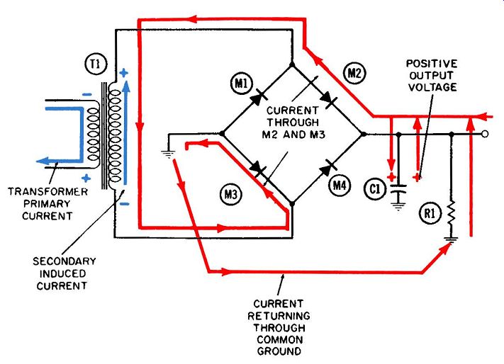
Fig. 3-6. The full-wave bridge rectifier-first half-cycle.
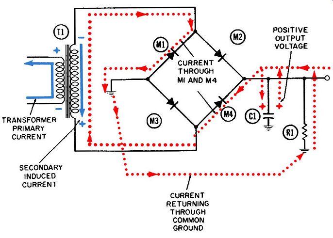
Fig. 3-7. The full-wave bridge rectifier-second half-cycle.
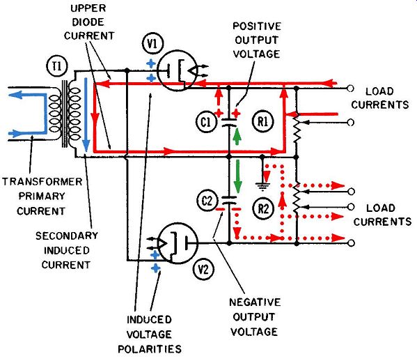
Fig. 3-8. The full-wave doubler rectifier-positive half-cycle.
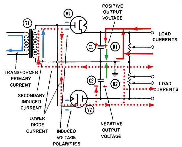
Fig. 3-9. The full-wave doubler rectifier-negative half-cycle.
FULL-WAVE VOLTAGE DOUBLER
Figs. 3-8 and 3-9 show two alternate half-cycles in the operation of a full-wave voltage-doubler power supply with transformer in put. The transformer used here might be identical to the one shown in Figs. 3-1 through 3-4. Because of the different circuit construction, however, the output voltage developed across out put resistors R1 and R2 will be twice the output voltage developed across R1 in Figs. 3-1 through 3-4. There are two important differences in the construction of the voltage-doubling circuit. First, the lower end of the transformer secondary is connected to ground rather than to the plate of the lower diode, V2. Also, the position of diode V2 is reversed from the previous example; here its cathode is connected directly to the plate of diode V1. In addition the junction of output resistors R1 and R2 is connected to ground; now this circuit will deliver both a negative and a positive output voltage.
Although two separate tubes are shown in Figs. 3-8 and 3-9, two halves of a single tube (with separate cathodes) are often employed. At other times, solid-state rectifiers such as used in Figs. 3-6 and 3-7 are utilized.
The necessary components of this circuit correspond as closely as possible to components doing similar jobs in Fig. 3-1. They include: R1 and R2-0utput resistors.
C1-Output filter capacitor.
C2-0utput filter capacitor.
T1-Power transformer.
V1-Upper-diode rectifier tube.
V2-Lower-diode rectifier tube.
For simplicity, the choke coil in Fig. 3-1 has been omitted from this circuit, and also the tertiary winding for heating the filaments.
Likewise, the filament heating current, shown in dotted blue in Fig. 3-1, does not appear in Figs. 3-9 and 3-10.
Identification of Currents:
Six principal electron currents are at work in this circuit, as follows:
1. Primary current in power transformer (blue).
2. Induced secondary current in power transformer (also in blue).
3. Current through upper diode V1 and its filter network ( solid red) .
4. Current through lower diode V2 and its filter network ( dotted red).
5. Two filter currents between C1 and ground and between C2 and ground (both green).
Details of Operation Fig. 3-8 has been designated the positive half-cycle of operation, because at this time the inductive action between the primary and secondary winding drives the upper end of the secondary winding positive. This positive voltage is indicated in Fig. 3-8 by the blue plus signs at the plate of diode V1 and also at the cathode of diode V2.
Diode V1 will conduct electrons, now that its plate is more positive than its cathode. This i:-; the current shown in solid red, and its complete path is from cathode to plate within the tube, then downward through the secondary winding and to the right.
Here it enters resistor R1, flows upward through R1, and returns to the cathode. Almost the full peak voltage which is developed across the transformer secondary winding is also developed across R1, since the lower end of it and the secondary winding are both connected to a common ground.
Electrons flow through diode V1 during only a small portion of the first half-cycle, when the plate reaches its peak positive voltage. During the remainder of this so-called positive half cycle, the cathode of V1 will be more positive than the plate. This is due to the integrating action of the filter system represented by R1 and C1. During that short period when electrons are being drawn across diode V1, this excess demand is provided from the upper plate of capacitor C1. This accounts in Fig. 3-8 for the upward flow of electrons leaving this plate, and also for the continuing positive voltage on it, as indicated by the red plus signs in Figs. 3-8 and 3-9.
During the nonconductive portion of the positive half-cycle, and during the entire negative half-cycle, electrons flow down ward onto the upper plate of capacitor C1. This direction of flow is indicated in Fig. 3-9 only. The filter current (shown in green in Fig. 3-8) between the lower plate of C1 and ground flows up ward when electrons are drawn away from the upper plate of C1 for passage through the tube. During the remainder of each cycle the current flows downward, as indicated in Fig. 3-9.
No current can flow through diode V2 during the first half cycle of Fig. 3-8 since its cathode is positive and its plate is negative (for reasons we shall discuss later). The positive voltage created at the upper plate of capacitor C1 is one of the output voltages of the power supply. It serves to draw electron current toward it from any load or loads to which it is connected. Two such load currents are shown in Figs. 3-8 and 3-9. One enters the filter at the main output tap, and the other through a potentiometer tap. Such a potentiometer could be made to provide a positive output voltage with any value be tween zero (ground) and the full output value.
During the second, or negative, half-cycle depicted by Fig. 3-9, the inductive action across the transformer makes the upper end of the secondary winding negative. This temporary negative voltage is indicated by the minus signs at the plate of V1 and the cathode of V2. At the negative peak of this half-cycle, the cathode of V2 will become more negative than the plate. As a result, this diode will conduct. The complete path of this current (shown in dotted red) is from cathode to plate within the tube, upward through R2, turning left to the lower end of the secondary winding. Then it flows upward through this winding, and downward to the cathode again.
R2 prevents each pulsation of plate current from flowing immediately to ground as it passes through the lower diode. Consequently, these electrons flow onto the lower plate of capacitor C2. A pool of negative electrons is soon created, and consequently a source of negative voltage. This pool of electrons persists during the entire cycle, and it drives a continuous electron current up ward through resistor R2, toward the ground connection. This current can be seen in Figs. 3-8 and 3-9.
The filter current which flows between capacitor C2 and ground changes its direction in accordance with the main electron current through diode V2. When V2 is conducting, electrons flow onto the lower plate of C2. This action forces the filter current to flow upward from C2, toward ground. When V2 is not con ducting, the filter current flows back onto the upper plate of C2 from ground. The latter condition is depicted most clearly in Fig. 3-8.
The three output points on resistor R2 constitute sources of negative rather than positive voltage. Negative voltages are required for various reasons in some types of equipment. A negative voltage source delivers electrons to a load, rather than drawing them away as a positive voltage source does. For this reason, load currents are shown flowing away from the various taps on resistor R2.
Since the full transformer-secondary voltage appears across each resistor separately, and since the two resistors are in series, the input voltage has in effect been doubled. As an example, if the peak primary voltage were 150 volts and the transformer turns ratio were 2-to-1, then the peak secondary voltage would be 300 volts. Thus, the positive output voltage on capacitor C1 measured between the upper plate of C1 and ground-would approach 300 volts, and so would the negative voltage output on capacitor C2, measured between the lower plate of C2 and ground.
A voltage measurement across the entire output-resistor path, consisting of R1 and R2 in series, would indicate a difference of 600 volts. This is twice the peak input voltage across the trans former secondary.