AMAZON multi-meters discounts AMAZON oscilloscope discounts
Lesson AEH -20 B
TROUBLESHOOTING A RADIO
ELECTRONS PENETRATE FOG
Fog was so thick that 60 vessels were forced to anchor and remain immobile for more than 14 hours in the winding St. Mary's River. Suddenly, the captains and crews on these ships were astonished to hear the 600 foot A. H. Ferbert steam past them at full speed ahead. These men did not know that this ship had been equipped with radar, and thus, electronically could "see" the shore line, docks, and other ships.
Radar can detect the distance to, the size, the direction, and speed of travel of objects which are beyond the visual range or hidden by darkness, fog, clouds, or rain. Developed originally for military use, radar now is employed for marine navigation, airfield tower control, blind landing of aircraft, by fishing boats to spot their catch, by the weather bureaus to locate and measure the velocity of approaching storms, and even by high way police to measure the speed of auto mobiles.
Fundamentals:
TROUBLESHOOTING A RADIO
Contents
First Inspection
Resistors Capacitors Transformers Tubes Hardware Dynamic Testing Static Testing Voltage Analysis Power Supply Signal Circuits Continuity Testing Point to Point Capacitor
Opportunity comes like a snail and once it has passed you, it changes into a rabbit and is gone. What is opportunity? It is a chance to do something, to give something, to achieve something, to climb out of the rut. To be some body of value in the world. Opportunity is life itself.
-Arthur Brisbane
TROUBLESHOOTING A RADIO
Every technician needs to know how to find trouble. The radio and television serviceman makes his living doing just that, but every other technician frequently needs to locate and set aright a defective circuit. He has either installed or built some equipment and it does not work as expected.
After examining a typical radio receiver a couple of lessons back, it should be apparent that troubles can be caused by any one of a number of parts in each of the different circuits. To find this fault by a haphazard "try this to see if it works" approach would be very time consuming and, in some cases completely ineffective.
Therefore, to be an efficient technician, one who seems to lay 'his finger right on the defect, you have to have a plan of attack that uses the minimum time and effort to determine the trouble.
This type of approach usually is composed of two major steps: First, find the circuit within the equipment that is not operating properly. Second, determine what in the circuit is defective and needs replacing. Everyone has a slightly different troubleshooting method, but efficient technicians all end up by using this basic approach to the problem.
Don't lose sight of it or you will find yourself wasting time testing things that have nothing to do with the problem at hand.
Another good rule of thumb to use is when more than one component is equally likely to be at fault always check the one most available; it saves time. Naturally, if one particular component of two is very prone to cause the fault observed, you check it first.
FIRST INSPECTION
Finally, troubleshooting starts immediately by being alert for little clues. All of your natural senses can be used to detect faults.
Don't assume that your test equipment must be laid out before the job begins. With the use of all your senses, except taste, and a good understanding of what each component and circuit can do, many faults can be discovered by being aware of exactly what is happening.
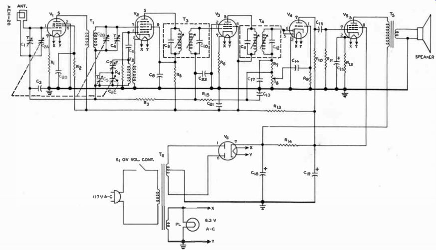
For example, suppose the receiver in Figure 12 plays intermittently when some one walks across the room. Here is likely what a good technician does. First he notices whether the dial light blinks too. If it does the power is being interrupted inside or out side of the receiver cabinet. If it doesn't something inside the receiver makes intermittent contact.
Next he would wiggle the volume knob to which the switch is attached. If that produced a similar effect and the light blinked, likely the trouble is in the switch, if the light didn't blink the volume control might have bad contact. Rotating it slowly up and down and listening for noise checks this point.
On the other hand, if no effect came from wiggling the control the fault either lies elsewhere in the receiver or outside. Since out side is handy, he would carefully check the cord and plug for defects and try a different outlet.
Only when these effects didn't yield results would the technician turn his efforts to the inside of the receiver. It would be a terrible waste of time to pull the receiver out of the cabinet when only the plug or outlet is at fault.
From this description it should be apparent that a good technician services by being alert to little details as well as making effective use's of instruments.
Without instruments, you can use your natural senses. With the exception of taste, these senses are important troubleshooting tools. There are the familiar parts which can be defective: resistors, capacitors, transformers, inductor, coils of all types, tubes, and batteries. Less noticed but equally as important, and often the most difficult to locate trouble in, or at, are such things as: mounting brackets, shielding cans, jacks, tube sockets, solder joints (especially ground connections), terminal strips, loudspeakers, cones, and foreign materials such as dirt, bugs, and moisture.
Therefore, before going into a description of how to service with a meter, we will just describe some things to look for.
Common defects w lich develop in most components a re "shorts" and "opens". A short is any condition which produces a lower than normal resistance between two given points in a circuit. An open is a condition in which conductors are separated so that current cannot pass.
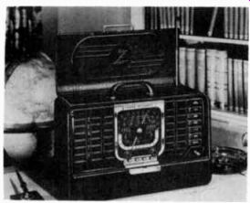
---------------- To make it easy to carry, this multi-band radio has a
number of circuits in a small space. Point-to-Point testing is a very effective
means of servicing it. Courtesy Zenith Radio Corp.
Resistors
When some circuit fault causes too heavy current in a resistor, the resistor overheats and be comes discolored. Some get so charred they are "dead black". Others may not discolor, but break or turn powdery and fall apart when jarred. Other signs of a too hot resistor are smoke or odors of burning paint. Usually, an other component is faulty also.
Capacitors
Capacitors are just a little more troublesome to locate. They can short, be leaky, change value, or open completely. In air dielectric jobs, such as a variable capacitor, bent plates touching together may be the fault.
Leaky capacitors conduct d-c all the time so they heat. This is especially true of electrolyte types.
Capacitors handling enormous power such as liquid filled units found in transmitters and industrial equipment do heat normally, but never enough to ooze or boil out the contained liquid. Cracked housing, chips, or even pencil cracks must be examined closely.
When the equipment is completely inoperative, very likely the power supply is at fault and the most likely fault is a leaky or shorted electrolytic capacitor.
Therefore, the first check to make for a completely "dead" piece of equipment is to remove all power immediately and measure the resistance from the cathode of the rectifier to ground. This can be made without even pulling the chassis by removing the rectifier tube and placing one ohmmeter lead in the socket hole for the cathode, and then using the other lead to touch the chassis of a receiver with a transformer or one side of the a-c plug on the ac/dc models. If the resistance is below normal or zero, the chassis should be pulled and the individual electrolytic capacitors checked to locate the faulty unit. This should be done before even replacing the tubes. Otherwise, good components will be ruined by the short.
Never lay capacitors on resistors, tubes, or any elements generating heat in electronic equipment. Moreover, since some capacitors are parts of tuned circuits, in servicing these should not be disturbed from their original position. The change can detune the circuit.
Transformers
Transformers, particularly power transformers, heat up normally. However, when overheated the odor of lacquer or varnish exists. When you detect such an odor, turn the power off promptly; you may save an expensive component. Usually an overheated transformer is due to a shorted electrolytic capacitor. Therefore, check the resistance from the rectifier cathode to ground. Only when the resistance from cathode to ground checks normal, should the transformer be suspected.
One shorted turn in a primary acts like a secondary. Since the ampere turns for the primary equals the secondary, then the shorted turn carries a heavy current. The result is over heating, low voltages, or the blowing of fuses.
Signal carrying transformers with a shorted turn ordinarily reduce the signal. In fact, some times the signal is blocked altogether since this one shorted turn tunes the circuit to another frequency. Inductors behave some what the same as transformers in so far as faults are concerned.
Tubes
The component most frequently at fault is the electron tube.
About 70 to 80% of the trouble is here. Many of the tubes have glass envelopes through which you can see when the heaters are on or not. Sometimes just feeling tubes to see if they are warm is enough, but don't expect tubes having type numbers such as 1B3GT, 1R5, or 1S5 to be warm.
Tubes in this 1 volt filament class operate cold. These are rated to operate at about 1.2 or 1.4 volts, usually d-c. On the other hand power rectifier tubes and power pentodes should be hot, but the plates shouldn't turn red or sparks fly in small equipment.
Not all faulty tubes have visible effects, and since they plug in easily and are so frequently at fault, it is a sound practice to re place the tubes with a set known to be good. If the trouble is cleared up, replace each old tube until the trouble appears. Thus the defective tube is found. This usually is done when preliminary inspection doesn't reveal any evidence of the fault. It saves removing and installing the chassis in many cases.
Hardware Mounting brackets sometimes are at fault. Other parts may be mounted on them, one side of which is grounded to the bracket, it in turn being grounded to the metal chassis. The connection be comes loose, corroded, or even broken. In any case, the circuit will not work normally.
Shielding cans on IF transformers are anchored with snap on clips or threaded lugs and some times are soldered to the chassis for a good ground connection. If the can gets loose, then with each jar of the equipment, tuning will change, and the set will operate erratically, fading in and out.
Any connector elements, such as jacks, tube sockets, and terminal strips have insulation material which ages and becomes leaky.
Normally, checked with an ohm meter their resistance reads close to "oc", but when the insulation resistance drops enough to obtain a reading definitely less than in finite, then they are suspects for causing trouble.
Of course foreign materials such as dirt, bugs, and moisture are great headaches. Dust or dirt on all components is harmful to their normal operating conditions.
Compared to other troubles in electronic devices, these are difficult to find and cure. As a result, the good technician removes such things as a general servicing practice no matter what other troubles exist.
These are items to watch for when you first pull the chassis. However, observation doesn't stop here. Often the performance indicates the nature or general location of the trouble. In fact, deliberately injecting a signal and observing what happens, helps to locate the faulty circuit.
DYNAMIC TESTING
Using the radio receiver in Figure 12 as an example, since a 60 cycle sound can be heard, part of the heater voltage can be coupled into the circuit to see if a signal comes through.
By connecting a capacitor to the ungrounded or "hot" side of a heater you can couple this signal voltage to the plate of the power amplifier at pin 5 of V. You should hear a hum through the speaker, if both speaker and transformer are good.
A harsh or weak sound would indicate a faulty part. Next the capacitor can be used to couple the heater voltage to the grid of the power amplifier at pin 7 of V.-, and then the grid of voltage amplifier at pin 1 of V,. In each case the sound should be louder but sound the same. Any loss of sound would indicate the added circuit was faulty. Finally when coupled between volume control IL and resistor RT, the sound should remain the same as on the grid of V4 when the volume control is rotated clockwise, and diminish smoothly as the volume control is turned down.
Going back further than the volume control with the 60 cycle voltage wouldn't work since V1 , V2, and V3 amplify only radio frequency signals.
Another variation of this procedure is the screwdriver test.
When two metal surfaces are rubbed together, small electric voltages or noises making up many frequencies are produced.
Therefore, rubbing the grids of V1, V2, and V: , with a screw driver blade often produces signals that can be heard as noises.
When these come through, it is a fair indication that the circuit does amplify although it might not perform some of its other functions.
Tracing the signal through the radio receiver in this manner to see what each tube does to the signal is called DYNAMIC TESTING. To make full use of the dynamic testing procedure, you must know a lot about how the circuit is sup posed to work so that an improper operation can be recognized and traced to its cause.
For example, a good service man can tell by looking at what is on the screen of a television receiver just about which tube circuit out of 16 or more can cause the particular trouble seen. There fore, he can go immediately to that part of the receiver for further troubleshooting. However, to do this, the technician must know exactly how each circuit performs.
For this reason most dynamic trouble shooting procedures are applied to the particular type of equipment you are interested in later in your study program.
STATIC TESTING
Once the general nature of the trouble has been found by dynamic testing, STATIC TESTING procedures are used. These include measuring the voltages and resistances in a circuit, rather than watching how the circuit handles the signal. To use static testing first would not be an efficient method. Rather than measure all of the voltages and resistances in the circuit of Figure 12, it is much better to locate the general area of the trouble by dynamic testing, and then measure these values only in this one area.
Static testing uses two important steps. First, the voltages are measured to see if they are normal. Once an abnormal voltage is found, the technician analyzes the situation to determine what most likely would cause the voltage to be high or low. This first step is called VOLTAGE ANALYSIS.
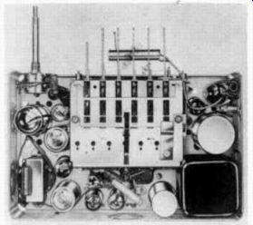
----------- Shown with the top cover removed is an auto radio. It has
circuits very similar to table model receiver, and so almost identical servicing
procedures ore used. Courtesy Motorola, Inc.
In the design of electronic equipment, the voltages are selected to provide optimum circuit operation. So long as these re main within about 20% of the design value, usually no appreciable change in operation is noted. However, when the voltage changes are greater, the circuit no longer performs as designed. Hence, measuring these various voltages and comparing them with the design values often locates that part of the circuit which is faulty.
However, in order to compare, the designed values must be known. Those listed in tube manuals only suggest possible voltages as a guide for designers. The actual voltages used may vary widely from these suggested values. Consequently most equipment manufacturers publish instruction booklets, schematic dia grams, and service data sheets containing part specifications, voltages, and resistances. The one exception to this general policy are some radio and television receiver manufacturers.
A common source of information subscribed to by many radio and television receiver service men are the manuals published by John F. Rider, Inc. of New York, and Howard W. Sams Co., Inc. of Indianapolis, Indiana.
These manuals give exact values for specific makes and models, and should be referred to when ever available.
Once the abnormal voltage is found, the serviceman measures the resistance of the suspected part to make sure it is the one at fault. This last step is made with the circuit turned off. Frequently these resistance measurements are called CONTINUITY TESTING. Possibly the best way to describe voltage analysis and continuity testing is to use individual circuits from Figure 12 as examples and Charts 1 and 2 at the end of this lesson list the voltages and resistances for this receiver.
In fact, these are quite typical for a table model receiver. In order to establish a common starting point, the conditions prevailing at the time the measurements were made are listed on the chart. For the technician to be sure his voltage or resistance readings give him a true indication of circuit conditions, he should strive to duplicate the listed conditions. Also, he should use a meter of the same sensitivity as that employed originally. If he does not, he must bear in mind that the meter itself may cause the circuit voltages to read lower than those listed due to the increased meter reading error.
VOLTAGE ANALYSIS
Power Supply
Since the power supply is the source of the operating voltages in any electron unit, it is good practice to test the power supply circuits first whenever the entire unit is inoperative or is operating improperly. Of course, when some sections or stages of a unit are observed to be operating properly, it is unlikely that the power supply is at fault, and the voltage testing may begin in the faulty stage or section.
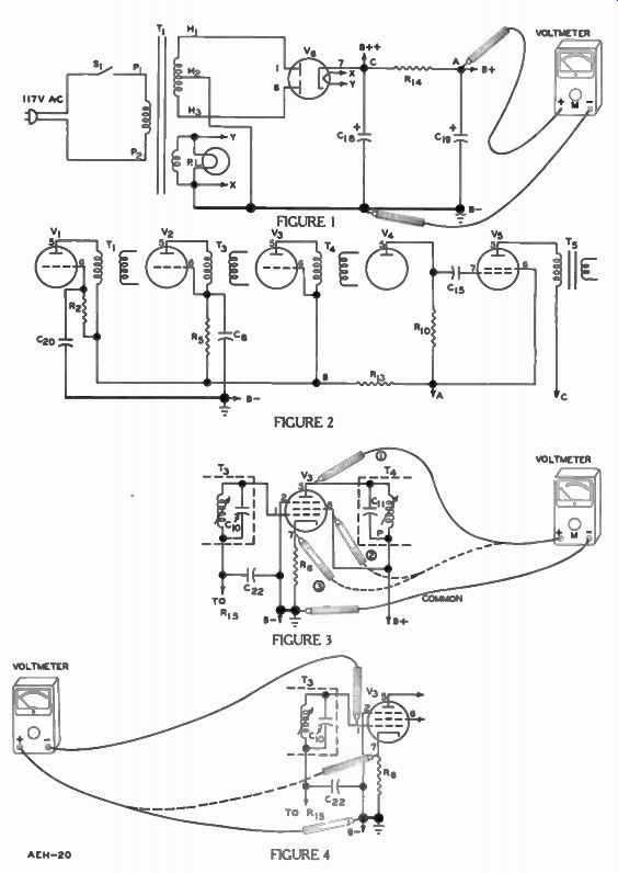
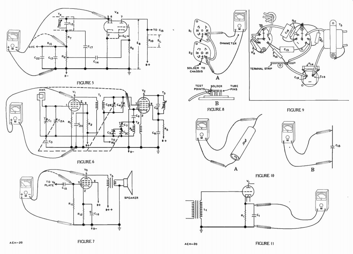
To illustrate the method of power supply voltage tests, the transformer type power supply used in Figure 12 is shown in Figure 1. Each plate of the full wave rectifier tube V6 connects to one end of the high voltage center tapped secondary and the filament is connected across the heater secondary of power transformer T6 as indicated by the letters X and Y. A pi type filter includes resistor R14 and capacitors C18 and C19.
We pointed out earlier that the electrolytic capacitors are very likely leaky or shorted when the receiver is completely "dead" or the transformer smokes. There fore, the first test on the power supply in Figure 1 is made while the chassis is still in the cabinet by pulling rectifier tube V6 and measuring the resistance from pin 7 to the chassis. According to Chart 2 this resistance should be 100 K ohms. If it is substantially less than this then very likely C18 or C16 is very leaky or shorted and needs to be checked individually. However, if the reading is near normal or above, it is safe to turn the power on and proceed with the voltage tests.
Therefore, assuming the initial inspection and tests have been made and the heaters of all the tubes light up to normal brilliance or heat to normal temperature, the primary and heater windings of the power transformer are very likely in good condition.
Therefore, with the receiver power turned on, the first check is made with the voltmeter prods at point A and ground, as shown in Figure 1.
Since the power supply provides a d-c output across points A and B - , the voltmeter must be a d-c instrument or a multimeter or VTVM set for d-c voltages. The exact voltage which should be present across these points may be found in a service manual or data sheet for the particular unit.
In this case it is Chart 1 at the end of this lesson. However, for equipment of the same general type the power supply output voltages do not vary a great deal.
Using radio receivers as an example, most power supplies of this type develop a normal output of 250 volts, plus or minus about 50 volts. Therefore, the voltmeter switch of the VTVM should be set on its 500 volt range. If the meter reading is more than 10% above or below the value specified or is beyond the general limits just given, it indicates a defect in either the supply or the external circuits to which it is connected.
The two most likely causes of a higher than normal voltage at Point A are an a-c line voltage above normal or one of the exterior circuits is not drawing normal current.
The first possibility can be checked by measuring the a-c voltage at an outlet or across transformer T1 primary at points P1 and P2. It should be the same as that used for obtaining the chart voltages. If it isn't, allowance must be made for the variation. If the fault is due to low current, the exterior circuits, that is the circuits around tubes V1 through V5 in Figure 12, need checking. Moreover, since V1, V2, V3 and V4 normally draw a small current, V5 is the most likely possibility.
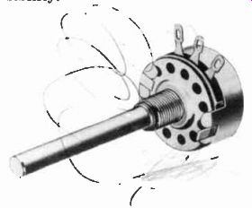
----------- Controls, especially the volume control, eventually become
noisy in radio and TV sets. Sometimes, a commercial contact cleaning fluid
placed in the slot immediately behind its terminals washes away loose particles
causing noise. Courtesy Ohmite Mfg. Co.
On the other hand, three different reasons can cause a lower than normal voltage: a low a-c voltage at the wall outlet, a defective power supply, or, some circuit connected to the power supply is drawing excessive current.
To determine the location of the defect causing the low voltage at point A, move the test prod from point A to point C. According to Chart 1, pin 7 of Vg is 250 volts and pin 6 of V5 is 240 volts, and since these are connected directly to points C and A, the voltage should increase about 10 volts when going from A to C. A larger voltage change indicates that too much current is passing through R14 or the resistance of R14 has increased. A normal change would indicate that the fault lies be fore R14.
Let's take the first condition first.
Open filter capacitor C18 may cause a greater reduction of output voltage than an open C19 but usually when either one is open it is indicated by a noticeable increase of hum. Completely shorted capacitors cause excessive heating of the rectifier tube and capacitor, a defect which should be observed during the initial inspection. But, filter capacitor defects which allow excessive leak age current can cause voltage drops like those explained for a high current in an external circuit.
To determine definitely whether the low voltage at point A is due to a large resistance in R14, a leaky capacitor C19, or excessive current in the external circuits, the B + wire connecting all exterior circuits to point A should be disconnected. If the voltage re turns to normal the external circuits need testing or the resistance of R14 is too high. If the volt-age remains low, very likely C19 leaks. As explained later in the lesson, R14 and C19 are checked by continuity test and replaced where necessary.
When point A is about 20 volts below point C, the fault is not very likely R14, C19, or the exterior circuits connected to B +. Either the B+ + line connected directly to point C draws too much current or the fault lies elsewhere.
Since the power line voltage may be low or an a-c component in the power supply may be defective, check the a-c voltages. If the voltage at points P, and P2 reads lower than normal, or zero, the power cord should be removed from the receptacle and a voltage test made at that point. With a low voltage at the receptacle, the trouble is in the house wiring.
With normal voltage at the receptacle and low voltage at points P1 and P2, there is a defect in the line cord, switch, or plug.
A visual check of the line cord chassis connections will locate the fuse which would be inspected.
The usual procedure is to make a continuity test of the line cord and fuse. This method is explained later in this lesson.
Next, check the secondary a-c voltages from H, to H2, from Ho to 113, and from X to Y. If any of these are below those listed in the chart, as the V6 plate and heater voltages, remove the plug and check the transformer windings by continuity test as described later. However, when these a-c voltages are normal three possibilities are left; Tube V6, capacitor C18, or the circuit connected to B + + is defective. Vg is checked during the preliminary inspection by replacing it. By removing B + - F - from point C the exterior circuits and C18 are checked. If the voltage returns to normal, the exterior circuit is at fault; if it remains below normal, then C18 must be checked for leakage.
As an example of the effects of an external circuit on the power supply voltages, suppose in Figure 2 that the voltages at points A and B were low but the difference in the voltages between these two points were about normal.
This would indicate that normal current was being conducted by R13. Since tubes V1, V2, and V3 all draw their plate and screen currents through this resistor, the short must be in the circuits about or V,. An extra large voltage drop across R13, on the other hand, would point to a short in the V1, V2, or V3 circuits.
For example, tube V2 has a screen bypass capacitor C8, which is in series with R13 and R5. There fore, a leakage or short in this capacitor will result in the abnormally low voltage reading at point B as well as pin 6. Therefore, a continuity or resistance check of these components also is necessary.
A short between the screen and grid in V1, V2, V, or V, all could produce the low voltage at point A. However, since it is sound policy to replace the tubes as a matter of routine in the preliminary steps, it isn't very likely the fault.
On the other hand, if one of the tubes wasn't replaced because you didn't have the type on hand, a quick check is to pull the tube out of the socket and see if the voltage returns to normal.
A more likely source of trouble is a leaky or shorted bypass capacitor like C2 4 or Cs, or a coupling capacitor like C15 or a short in the tube sockets between terminals, or between primary and secondary windings of trans formers like T1, T, or T. Also, there is always the possibility of defective insulation on wiring, bad tie points, etc. Once suspected, most of these can be traced down by continuity testing although by temporarily disconnecting the component from the B+ line to see if the voltage returns to normal is a positive check. Regardless of the order in which the power supply voltage tests are made, when proper voltage readings have been obtained at all of the key test points described for Figure 1, the power supply is in good condition, and any trouble that exists is in some other section.
Although variations of these circuits and other types of power supplies are in use, in every case they contain key test points which correspond to those in the dia grams of this lesson. The above outline of power supply testing has been given on the basis of using a minimum number of tests either to eliminate quickly the power supply section as the source of trouble, or to determine that the defect is in the power supply or in any B supply or heater circuits that are capable of affecting the power supply voltages.
If the trouble does lie in the supply or in circuits which affect the supply voltage readings, the chances are that this will be the only defect in the entire electron device. After it is corrected, further tests of the unit will be un necessary. Just turn the receiver on for a while to see if the operation remains normal. On the other hand, if the power supply and closely associated circuits and components are in proper condition, this knowledge is gained quickly by means of these voltage tests, after which the technician can turn his attention to checking the other sections of the receiver.
Signal Circuits
The various power supply checks described for Figure 1 indicate the nature of the B + and heater voltages at the output of the supply, but do not show that the required voltages reach the desired points in the other circuits of the unit, such as at the tube socket terminals. Since not more than one or two defects occur at a time, troubleshooting time is wasted when voltage and continuity tests are made in stages which are not defective. There fore, after tests have been made as explained, it is good practice to employ dynamic testing to isolate the trouble, to a particular section or stage of the unit and to make voltage and continuity tests only in the circuits so located.
Once it has been determined which stage is faulty, the first voltage tests are made at the tube socket lugs to determine the operating voltages applied to the plate, screen grid, control grid, and cathode of each tube in the defective section or stage.
The circuit of a typical amplifier stage is shown in Figure 3 in which the signal is coupled by in put transformer T3 to the grid of amplifier tube V3, and from the plate of V3 to the following stage by means of output transformer T4.
To make these tests, first the common or negative test prod is placed at a B- point in the circuit, as shown in Figure 3.
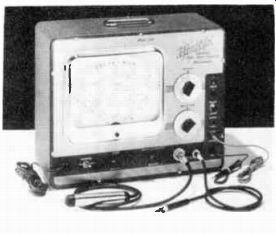
---------- This vacuum tube voltmeter and capacitance checker is used
not only to service radios, but TV sets, and other electronic equipment as
well. The capacitance checker is just added scales for the ohmmeter to indicate
the proper kick for each size capacitor. Courtesy Hickok Electrical Inst. Co.
When the chassis is at B- potential, the voltmeter negative test lead may be applied at any convenient point on the metal chassis As shown by the solid line 1 and dashed lines, 2 and 3, Figure 3, the voltmeter positive test prod is touched to the appropriate tube socket lugs in turn to check the plate, screen grid, and cathode voltages. In each case, the readings obtained are checked against the values given in a service manual or manufacturer's data sheet like chart 1, or those known to be approximately correct for the particular type of equipment.
These sources usually give values as measured from the various tube socket lugs to the receiver common B- point. Technically speaking, plate, screen, and grid voltages are those existing respectively from plate to cathode, screen to cathode, and grid to cathode. Thus, on this basis, a plate voltage should be measured with the negative test prod at the cathode socket lug. However, when readings of B + voltages at points in the circuit other than tube elements are to be made, the B - point is the proper reference, and so to simplify the entire process, MOST SERVICE MANUALS LIST ALL VALUES WITH REFERENCE TO B- ; therefore, the tube voltage tests are made as shown in Figure 3.
This removes the need to move the common or negative lead from one tube cathode to another and is the method used for measuring the Chart 1 voltages.
Since the control grid usually is operated negative with respect to the cathode of a tube, and negative or at zero potential with respect to B-, the test leads must be reversed to make this measurement. That is, the positive test prod is placed at B- and the negative prod at the grid socket lug, as shown by the solid lines in Figure 4. Actually, the total grid-to cathode negative bias includes the voltage across cathode resistor R,,, when this voltage drop is to be included in the measurement, the positive test lead must be placed at the cathode socket lug as indicated by the dashed line in Figure 4.
Most vacuum tube voltmeters incorporate a polarity reversing switch which makes it unnecessary to reverse the test leads to check negative voltages. With this arrangement, the test leads are used the same as for the positive voltage tests of Figure 3, except that the reversing switch is turned to "-D.C. VOLTS" when the control grid voltage is checked.
As explained earlier, since the various voltage charts normally give all voltages as measured from the tube socket lugs to B - ; the method of measuring grid operating voltages usually is used as indicated by the solid-line test leads in Figure 4.
Plate and Screen Voltages
Once a tube voltage has been found to be abnormal, the technician is well on his way to discovering the circuit defect. For example, in the circuit of Figure 3, suppose the check at the plate of tube V: , results in a reading of zero on the meter although the chart lists 112 volts for that point As the preliminary tests have shown that the proper B+ voltage is present at the output of the power supply, it now is evident that a defect must exist in some component, wire, or connection forming a part of the circuit between the plate of V3 and B+. Further isolation of the fault may be obtained by making a second voltage test as shown at point P, Figure 3. At this point, the reading should be practically the same as the voltage specified in the chart for the tube plate, since normally there is very little drop due to the plate current in the primary of T4.
If the proper voltage is found to be present at point P, then an open exists in the primary of T4 in the leads, or connections between this winding and the plate of tube V3 or between the winding and point P are open.
If a zero voltage reading is obtained at point P, then there may be a short in V1, V2, or V3 plate or screen circuits, or an open in the circuit between this point and B+ such as in R13. Any of the components, wiring, or the circuit connections upon which the voltage tests have thrown suspicion may be given a continuity or resistance test, using an ohmmeter in the manner explained later in this lesson.
Many circuits do not employ resistors such as R5, Figure 12, and the plate voltage of the tube normally is at B + potential less the small drop across the transformer primary as shown by V3 in Figure 3. In such a case, the plate voltage test does not disclose much.
However, for any tube where the plate circuit contains a series resistor R5 as in Figure 12 or in the case of a resistance coupled amplifier stage, an abnormally low reading indicates an excessive plate current. One common cause of this condition is lack of grid bias due to some defect. Also, an open cathode circuit will be indicated by a higher than normal plate voltage reading.
Figure 5 shows why measurement of the plate voltage indicates these conditions. The plate to B - voltage for V4 is indicated as E_B. EL represents the voltage due to plate current in resistor R10.
Since the total voltage between B+ and B - remains essentially constant, the increase in voltage EL is accompanied by a corresponding decrease in E.. And as mentioned, E. is measured by the meter in checking the tube plate voltage.
Since the decrease in E. is due to an increase in voltage across R10 in the case of stages in which the plate circuit does not contain a series resistor, a defect may not be discovered until the cathode or grid voltage is measured.
------------ A signal tracer is a detector, amplifier, and speaker used
to trace a signal through every stage of a radio. McMurdo Silver Co., Inc.
If the original plate voltage test results in an abnormally high reading, then it is likely that the cathode resistor, which carries both the plate and screen currents, is open. Thus, with an open in cathode resistor R1 of Figure 12, the plate and screen currents will be zero, there will be no voltage drop across R2 and at the plate of V1 the voltage will equal that at B +.
A second cause for the abnormally high reading is an open grid circuit. For example, if antenna loop is open, the grid of V1 in Figure 12 has no cathode d-c path to ground. The few electrons that hit the grid on the way from cathode to plate would collect on the grid until it became so negative that the tube cuts off.
This condition is referred to as a "floating grid". Frequently when a temporary connection is made to ground by means of a screwdriver or even the meter, the radio will play after the connection is removed until enough electrons collect to bias the tube beyond cut-off again.
Similar circuit defects may be the cause of an abnormal screen voltage reading. That is, a zero reading indicates an open some where in the d-c circuit between the screen socket lug and B +, or a shorted bypass capacitor. A high screen voltage reading indicates that some circuit defect is causing the screen current to be low or zero, while an abnormally low reading is indicative of excessive screen current due to some circuit fault, such as a shorted by pass capacitor.
Cathode Voltage
Insufficient or complete lack of cathode voltage may be due to a snorted or leaky bypass capacitor or to some condition which limits or prevents the screen current, plate current, or both. If there is an open in the cathode circuit, such as in R1 of Figure 12, there is no current and very little voltage drop in the tube or the resistors between the tube plate or screen and B +. Therefore, the cathode voltage will be very high; practically equal to B + Grid Voltage In the case of stages employing self bias as in Figure 3, lack of or excessive negative grid bias voltage may be due to defects in the cathode circuit components or abnormal plate and screen currents.
For equipment where a fixed bias is used, it may be necessary to take voltage readings at various points in the grid bias supply circuit as described for the power supply of Figure 1 in order to locate the component or connection which is causing the trouble.
A positive voltage reading may be obtained at a control grid due to leakage of the capacitor which couples the signal voltages to this grid from the plate of the preceding stage. The rare exceptions are amplifier stages designed to operate with the control grids positive with respect to B-. However, even in these cases normal operating conditions prevail, since the cathodes of these tubes are operated still more positive than the grids.
Detector and AVC
The detector performs two things. It removes the audio signal by rectifying the r-f. Once this is performed, there is an additional function: it provides part of the rectified voltage as an automatic volume control for the in coming signal. In Figure 12, the detected signal is fed by C74 to the audio amplifier and the AVC voltage from the top of R8 is fed through a filter consisting of R15, R3, C22, and C3 to the previous three tube grids.
Returning to Figure 5, with no signal into the circuit, the voltage measured from pin 5 to ground is due to a tube noise. As a result, the voltage at the junction of R7 and R8 is usually about-0.4 volt d-c as shown in Chart 1. In addition, any voltages measured at the grids of V7 , V2, V3 is due to their own self-bias properties.
And the only way to tell that the AVC is operating properly is to have a signal passing through the radio. However, unless this signal is controlled there may be improper AVC action due to other causes. Here is one specific service technique which requires the very thorough knowledge of a-c circuits.
RF Amp and Converter
Most of the comments on voltage checks hold true for RF AMP of Figure 12 as shown in Figure 6. In addition, some comments should be noted on the oscillator action within tube V2. You may recall that V2 has a tuned-grid oscillator. The tuned circuit of the oscillator consists of C2c, C5e Co, C7, and T2. Primarily, C8 and R4 provide the grid-leak bias for, V2. In the cathode circuit, the winding of T2 is the feedback winding to maintain the oscillations. Since grid-leak bias is produced by rectifying the signal applied to the grid, and in an oscillator the only signals are the oscillations, a bias indicates that the circuit is oscillating. This d-c check is shown in Figure 6 using ground and the dotted connection line to pin 1 of V2.
Power Amplifier
Frequently, the power amplifier tube in Figure 7 causes trouble since it handles more power than several of the other tubes in Figure 12 put together. Other than the tube itself, capacitor C15 breaks down about as often since it has the plate voltage of practically all of V4 across it. When this happens, the positive grid for V5 is a sure sign of such trouble.
Since it does handle so much power, the tube will draw enough current to cause damage very quickly were it not for the cathode self bias of C16 and R12. C16 may be leaky and, for a low cathode to chassis voltage, a continuity check should be made to determine whether this is the defect.
Note that the plate voltage is applied through the primary winding of T5 from the junction of C18 and R14 labeled B+ +. This enables the tube to operate at a higher voltage. Figure 7 shows the VTVM connections for measuring the plate voltage from pin 5 to ground.
In each of the Figures 1 through 7, once the voltage check has been completed in a stage and an incorrect reading is obtained, further checks are necessary to locate the exact component. Thus, the voltage checks in general tell whether the trouble is in the cathode, control grid, screen grid or plate circuit. To pin point the exact part causing the trouble, continuity checks must be performed.
CONTINUITY TESTING
Modern chassis design makes it impossible to trace most connecting wires visually, moreover a defective resistor, coil or capacitor may appear to be in perfect condition. Therefore, electric tests must be made to determine which parts are defective. Fortunately, most of this work can be done with very simple equipment using continuity testing.
The word CONTINUITY means uninterrupted connection, and in regard to electric and electron circuits, is defined as the presence of a complete, or continuous path for current. For service work, this definition usually means a complete, or closed, circuit for direct current only, and depending on the purpose of the circuit, it may contain a large, moderate, small, or zero resistance.
Because of the range of resistance that may be employed in the various circuits, most service manuals include charts like Chart 2 that list the resistance between two selected points, usually but not always the socket lugs and the chassis or common B - point.
Like voltage measurements, resistance measurements are made under certain conditions, and the technician must duplicate those conditions if the readings he obtains are to have real meaning.
Variations up to about 20 percent between the actual resistance and those listed in any circuit may be caused by resistor and other component tolerances. Greater variations are due to component failures which may be discovered by checking each component and wire between the points with the abnormal reading.
Point to Point
As one form of continuity testing, POINT-TO-POINT testing consists of checking the resistance or continuity between two points in a circuit.
The wiring of the majority of modern radio and television receivers especially those using printed circuits and other electronic equipment is very compact, and many of the component parts are shielded so that they are out of sight. In such cases, continuity or point-to-point tests are the practical method.
An example of a test of this kind is illustrated in Figure 8A where an ohmmeter is being used to check the continuity between the terminals of two tube sockets.

---------- Shown is one type of tube checker. It tests the tube while
operating in a circuit built in the instrument. Courtesy Hickok Electrical
Instruments Co.
Since terminal Number 3 of socket S, is connected directly by a wire to terminal 3 of socket S2, the resistance between these terminals should be almost zero. The resistance of the connecting wire is so low that it will not be indicated by the usual service type ohmmeter.
The lowest ohmmeter range should be used for this type of test, and the test prods should be held tightly against the socket terminal lugs rather than on the soldered joints. If a reading of zero resistance is obtained under these conditions, the connection may be considered in good condition. Should a higher resistance reading be obtained, a "high-resistance" soldered joint or a break in the wire is indicated. However, before proceeding, the test prods should be touched together to make sure the "zero adjustment" of the meter is still correct.
In the case of a connection of this kind, the soldered joints are the most likely offenders. The solder may cover the joint, but the wire is loose inside of it, or not even connected. These are called "cold" solder joints. These may be checked by placing one test prod on the bare wire and the other on the socket lug, as indicated in Figure 8B. A zero reading should be obtained, but if the meter indicates resistance, a hot soldering iron should be held against the joint until the solder melts and flows. After cooling, the joint should be re-tested.
The connecting wire itself may have broken inside the insulation to cause a very high, if not infinite resistance. In any case, the continuity of the wire may be checked by placing the ohmmeter test prods on the ends in such a way as not to include the solder joints.
Instances of broken wires in cases of connections of the type shown in Figure 8A are rather rare; it is more frequently en countered in wires that may be moved. Examples of these are the a-c power cord, and tube grid cap wires.
In Figure 8A, a short wire of sockets S1 and S2 is connected from terminals 4 to ground. Each connection from the terminal to ground should have zero resistance. A zero resistance indication using the Rx1 VTVM range shows that the connections between these points are all right. To check the connection at S1 , remove the tube from socket S2. This is done since the heaters which are pins 3 and 4 of the two tubes are in parallel.
Thus, one parallel connection may be good while the other may not and checking the two connected together is no check at all.
When the tube pins are exposed, the surest check is to touch pin 4 of the tube with the other ohmmeter lead touching the chassis at a place not on the solder connection. You may meet up with a cold solder joint, but by placing the test lead on the solder ground point, you press the lead against it and complete the connection.
As for touching the tube pin, the socket lug itself may be making poor contact with the pin. Thus, the sure deck is to check from pin to chassis.
A high resistance requires a further check to isolate the poor connection. For instance, pin 4 to chassis ground reads 1 megohm.
Checking from pin 4 to socket lug of S1 , you read zero. From lug 4 to the solder on the chassis, you still read zero. From the solder on the chassis to the chassis, you read 1 megohm.
To cure a cold solder joint, take your soldering iron, properly cleaning off old solder and corrosion are necessary, and resolder the wire properly. As a final check, make an ohmmeter test from pin 4 to the chassis. You should read zero.
Then replace the tube in socket S., and remove the tube from socket S, to perform the same point to point check for the S., connection to ground.
Let us suppose that with dynamic checking we have isolated the trouble to tube V, and the under-chassis view of this part of receiver looks like Figure 9. We can check the continuity of the resistors, transformer L, and other components. We can check the continuity of It, by placing the ohmmeter test leads from the bare wire attached to pin 7 of V, and the bare lead of R1, connected to the chassis by the solder lug.
To include these connections, the same procedure outlined for heater checks is followed. That is, check from chassis to pin 7. In our receiver, the grid resistor is about 1 megohm, so if the range selected is R x 100,000, the pointer should indicate about 10 on the dial.
Resistor R1 , can be checked the same way, that is from pin 2 to solder lug, but this time using the R x 100 range. The pointer should indicate about 2.7 or read as 270 ohms.
To check the continuity of the primary of n, connect the ohm meter leads to lug 5 of J5 and to the junction of C18 and R14.
A reading of several hundred ohms should be obtained. If not and a high resistance of say 1,000 ohms is obtained, the transformer has been damaged.
When a part changes value, further checks should be under taken to be sure another part failure did not cause the change.
For example, a burnt out transformer winding would lead one to suspect lug 5 of the V5 socket of being shorted to ground.
Capacitor Testing
When in proper operating condition, a capacitor consists of two conductors, in the form of plates, rolled sheets or electrodes, insulated from each other by a dielectric. When the dielectric breaks down or is punctured, so that the plates come in contact with each other, the capacitor is shorted.
When an external lead wire be comes disconnected from its plate, the capacitor is open and again, in most cases, it must be replaced.
Capacitors are classed in several ways: According to their use as filter, coupling, tuning, bypass, trimmer, and padder; according to their shape as tubular, disc, button, postage stamp, and bath tub; or according to their dielectric such as paper, mica, oil, air, ceramic, and electrolytic. Also, they are rated in capacitance, or and d-c working volts, "WV" or "WV DC". However, insofar as tests are concerned, the main distinction must be made between electrolytic capacitors and others. Not only are electrolytics polarized when in good condition, but they allow leakage current which would indicate a short for capacitors with other dielectrics.
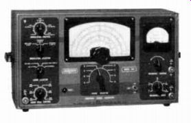
--------------- This service type instrument generates a wide range of frequencies which are needed to tune oscillators and i-f transformers to their proper frequencies. Courtesy Jackson Electrical Instrument Co.
Although special testers are available, capacitors can be checked for leakage by applying the test prods of a series type ohm meter across the terminals as shown pictorially in Figure 10A and schematically in Figure 10B. For good paper type capacitors, the capacitance of which is greater than .01 microfarad, the meter pointer will jump or "kick" slightly, when the test prods are touched to the leads, and then at once drop back toward the high end of the ohms scale. This shows that the direct current from the meter battery charges the capacitor, but as the pointer drops back toward infinity on the ohms scale it indicates that the dielectric is in good shape and the capacitor is all right. No pointer deflection indicates a probable fault of an "open". In most cases the terminal lead has broken loose from the capacitor foil or plate.
With the capacitor charged in this manner, removing and re placing the test prods on its terminals should cause no deflection of the meter pointer. However, a recheck of the condition of the capacitor can be made by reversing the test prods and touching them again to the capacitor terminals. This will allow the capacitor to discharge and then charge again in the opposite direction, causing an even greater initial kick of the meter pointer.
A back-up type ohmmeter is not satisfactory because the meter pointer is at full scale and the capacitor charging current is so small that its shunting effect will not cause a change of the pointer position.
Although giving a reading of infinite resistance on ordinary ohmmeters, good capacitors of this type do indicate a definite resistance after the initial needle kick, when they are checked with very sensitive ohmmeters of the VTVM type. The dielectric of a capacitor is not a perfect insulator, and therefore, it has some finite resistance. The present standard insulation has a resistance of around 500 megohms for a one microfarad paper capacitor and this rating can be used as a rough check as to whether or not a capacitor has a leaky dielectric.
In the event the capacitor di-electric is defective or broken down so that the plates touch each other, the ohmmeter will read a steady low or zero resistance.
For tests of this type, be sure to disconnect one capacitor lead to avoid inaccurate readings due to parallel connected units. For example, in the circuit of Figure 11, capacitor C1 is connected as a by-pass in parallel with bias resistor R1. With the test prods in the positions shown, both R, and C, affect the meter reading, thus making it useless for testing either one separately.
Sometimes the plate of a vari able capacitor is bent out of shape sufficiently to touch and provide a low resistance d-c path.
To test for this trouble, first disconnect any coils that may be connected across the capacitor, and then touch one of the ohm meter test prods to the rotor and the other to the stator of the capacitor section that is suspected of being defective. Then the rotor is turned slowly, and if and when it touches the stator plates, the ohmmeter will indicate very low or zero resistance. If the capacitor plates are correct and do not touch, the ohmmeter reads infinite resistance during the full turn of the rotor.
Electrolytic capacitors present a little different problem because they are polarized, and also be cause they allow a small leakage current even though they are in good condition. Therefore, when a capacitor of this type is tested with an ohmmeter, the prod connected to the positive of the meter battery should be placed on the positive terminal of the capacitor.
The dielectric of an electrolytic capacitor consists of an insulating oxide film which has the property of allowing heavy current to pass in one direction and very little in the opposite direction.
Thus, when one of these capacitors is subjected to reversed polarity, the heavy current will raise its internal temperature and may cause serious damage to the unit.
However, the oxide film on the capacitor anode plate is not harmed by reversed polarity except when sufficient heat is generated.
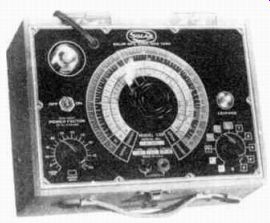
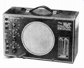
-------------- 471 A capacitor analyzer, as illustrated here, can be used for checking paper (or mica) and electrolytic capacitors for capacitance and leak age. Leaky capacitors cause intermittent and erratic receiver performance. Courtesy Solar Manufacturing Corporation
Therefore, a short application of reversed polarity does not injure the capacitor.
When ohmmeter test prods are placed across the terminals of a good electrolytic capacitor, C16 in Figure 9, and its ground is disconnected, the meter indicates a comparatively low resistance, but almost immediately the deflection of the meter pointer changes slowly until a fairly high resistance is indicated. As explained above, this action is due to the current which charges the capacitor. It is heavy at first and then drops gradually to a final value determined by the leakage resistance of the unit.
When making this test, always take a second reading, with the ohmmeter test prods in a reversed position, to check the polarity of the test voltage. The highest indicated resistance can be considered as correct but be sure the meter hand has stopped moving before taking the final reading.
While it is difficult to make a general statement as to what resistance a good electrolytic capacitor should have, field observations indicate that the average 20 pf filter capacitor rated at 150 WV DC has a resistance of 150,000 up to perhaps 500,000 ohms. An 8 pf capacitor rated at 450 WV DC usually has a resistance of between 250,000 ohms and 1 megohm. In either case, a new capacitor shows a somewhat lower resistance, but the value increases as the capacitor has been in operation for a short time.
If the ohmmeter pointer shows little or no deflection when the prods are placed on the terminals of an electrolytic capacitor, it indicates that the capacitor is either open or has low capacitance. In either case it should be replaced.
On the other hand, when the meter pointer indicates low or zero resistance and retains this reading for a minute or so, it is safe to say that the capacitor is shorted internally and should be re placed. Thus by watching the ohmmeter pointer, the condition of an electrolytic capacitor can be checked quite accurately.
SUMMARIZING:
(1) when the meter shows an initial low resistance but changes quite rapidly to a higher resistance reading, the electrolytic capacitor is presumably in good condition, (2) when the meter shows little or no deflection, or gives a continuous low resistance reading, the unit can be presumed to be in need of replacement.
In this lesson we have described for you an effective method for troubleshooting the radio receiver in Figure 12. However, bear in mind that the very same methods used here apply equally well to every other type of electronic equipment. An organized approach along with an alertness to the significance of each reading soon leads one to the defective part.
Only one type of test equipment was shown in this lesson. There are others. These are described after the fundamentals are presented which make it possible to use this added equipment effectively.
Take a look at the lessons studied and notice how much you have learned already. As you progress, you find this information increasingly valuable to you.
SUMMARY
Troubleshooting procedures for locating and correcting a fault in any electronic device require a planned and systematic, approach. First, it is necessary to isolate the circuit containing the fault. Then, determine what part or parts cause failure or unsatisfactory operation of that circuit. Next, the part is checked, and if a satisfactory repair cannot be made, it is repaired.
Finally, an operational check is made to confirm normal operation.
In such a planned procedure, the first step is a careful inspection of the device using the natural senses of sight, hearing, and smell-these are very valuable aids in the detection of trouble.
When the initial inspection doesn't provide a clue as to the nature of the fault, dynamic tests are made. These tests consist usually of tracing a signal through the various stages of the electronic equipment being serviced.
An abnormal signal indicates a faulty stage.
Once the general location of the fault is known, static tests are made to isolate the particular part causing failure or abnormal operation. Static tests include voltage analysis, resistance measurements, and continuity tests, the latter usually done with an ohmmeter.
Complete failure of a part or a component is due to an "open", which is a broken current path, or a "short" or unwanted current path. Abnormal operation of a device usually means the desired characteristic of a component has changed beyond its normal tolerance.
Effective troubleshooting is the result of correctly interpreting the meaning of tests or measurements made in a logical sequence.
---------
CHART 1 VOLTAGE MEASUREMENTS All voltages measured with an electronic voltmeter from socket lugs to the chassis.
Volume control turned to maximum clockwise position, no signal applied.
Line=117 v a-c.
CHART 2 RESISTANCE MEASUREMENTS
All resistances except as noted measured from the socket lugs to the chassis.
* Measured from lug 7 of socket V6.
Line cord removed from a-c outlet and volume control turned to maximum clockwise position.
--------
--------
FROM OUR Director’s NOTEBOOK
THE MAN WHO QUITS
The man who quits has a brain and hand
As good as the next; but he lacks the sand
That would make him stick, with a courage stout,
To whatever he tackles, and fight it out.
He starts with a rush, and a solemn vow
That he'll soon be showing the others how;
Then something new strikes his roving eye,
And his task is left for the bye and bye.
It's up to each man what becomes of him;
He must find in himself the grit and vim
That brings success; he can get the skill, If he brings to the task a steadfast will.
No man is beaten till he gives in; Hard luck can't stand for a cheerful grin; The man who fails needs a better excuse Than the quitter's whining "What's the use?" For the man who quits lets his chances slip, Just because he's too lazy to keep his grip.
The man who sticks goes ahead with a shout, While the an who quits joins the "down and out."
-Charles R. Barrett
Yours for success,
-DIRECTOR