AMAZON multi-meters discounts AMAZON oscilloscope discounts
ELECTRONS BAKE CAKES
Within 90 seconds after the batter is poured into the pan, it rises to form a smooth even texture, and the baking of a cake is completed. Instead of in the oven, the cake pan has been placed between two electrodes and an electric field generates the heat within the batter. Thus, it is un necessary to wait the usual long period of time while heat penetrates inward slowly from the surface.
Known as dielectric heating, this process is used whenever quick, carefully controlled heating is required throughout the entire object. Other typical applications include molding plastics quickly from a powder, setting the glue quickly between thin sheets of wood to form plywood, curing rubber in tires and foam mattresses, "sewing" plastic cloth, and as diathermy, to reduce soreness, aches, and pains in the bodies of patients.
Fundamentals
R, L, and C
Contents
Resistance of Series Circuits Resistance of Parallel Circuits Measuring Electron Tube Voltages Resistor Combination Circuits Series Inductors Parallel Inductors Series Capacitors Parallel Capacitors
Voltages Across Capacitors
Appendix A--Equivalent Resistance of Parallel Resistors
Our best friends and our worst enemies are our thoughts. A thought can do us more good than a doctor or a banker or a faithful friend. It can also do us more harm than a brick.
-Dr. Frank Crane
R, L, and C
Regardless of its particular application, every electron circuit contains at least a little of each of the three properties, resistance, inductance, and capacitance.
Whether we want them there or not, these properties are always in a circuit due to the materials of which the circuit is construct ed. In any given circuit, the properties due to its construction usually are not concentrated at a point. Instead, they are spread all along the circuit. For this reason, we call them the "distributed" properties. When concentrated in the form of resistors, inductors, and capacitors, these same properties are known as the "lumped" properties.
Since nearly all practical circuits contain lumped properties, it is this form which is under stood ordinarily when the words resistance, inductance, and capacitance are used. The terms distributed and lumped are needed only when there is danger of mis understanding in a particular case.
Normally, resistors, inductors, and capacitors contain a much larger amount of the respective properties than there is of the distributed type in a given circuit.
Therefore, for most practical purposes, when a circuit contains one or more resistors, we simply assume that these resistors contain all of the circuit resistance. The same assumptions are made in the cases of inductors and capacitors. That is, in practice, we ignore the small distributed properties. The few exceptions to this rule are certain special cases which are better covered when the need arises.
Depending upon the meter measurement being made, certain circuit conditions result in erroneous indications of voltage or current. These errors are not the result of poor meter design.
Instead, they are due to the effects which the meters have on the circuits in which the measurements are made. These effects are described in this lesson. Whenever a meter is connected to or into a circuit, the meter itself becomes a series or parallel section of the circuit. Therefore, to aid your understanding the various effects to be described, we shall begin with a review of the basic series and parallel circuits.
In such circuits, Ohm's Law can be employed to calculate either the resistance of, current in, or voltage across a single resistor. However, many practical circuits contain more than one re resistor. Often, it is desirable to compute the circuit current which will be produced in such a circuit by a given applied voltage. Ohm's Law can be applied here too, once we have determined the resistance of the entire circuit. Similar calculations also are employed with circuits containing inductance or capacitance.
RESISTANCE OF SERIES CIRCUITS
Figure 1A shows a voltage E applied to the terminals of a circuit containing a resistor, R1, and an ammeter, A. The applied voltage is obtained from any suitable source such as a battery or generator. As you will recall, Ohm's Law can be employed to find the value of either E, R1, or I1 , pro viding the other two quantities are known.
As an example, suppose we desire to find the applied voltage, when R1 is known to be 50 ohms, and the ammeter indicates a current of 3 amperes. We use Ohm's Law in the form which states that voltage is equal to current times resistance:
E=3 x50=150 volts.
For a second example, suppose the applied voltage is 250 volts, the circuit current measures 10 amperes, and we desire to know the resistance of the resistor. We then use the Ohm's Law form which states that resistance is equal to voltage divided by current:
R1=25 ohms.
Finally, suppose we desire to check the accuracy of the ammeter reading by means of Ohm's Law. Here we employ the form which states that current is equal to voltage divided by resistance.
If E is known to be 120 volts, and R1 equals 10 ohms, the meter should read:
I1=12 amperes.
As an experiment, suppose we replace resistor R1 of this last ex ample with a 20 ohm resistor, R29 as shown in Figure 1B. The applied voltage is still 120 volts, but we have doubled the circuit resistance. With greater resistance in the circuit, current 1 2 should be less than I1 of Figure 1A. That this idea is correct is shown by the ammeter which read 12 amperes with R1 but reads only 6 amperes with R2 in the circuit.
Checking with Ohm's Law: E R, 120 1,= = 6 amperes.
20
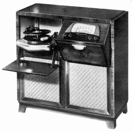
---------------- An AM/FM. radio-phono combination. Equipment such as this incorporate o considerable number of each of the types of circuits described in this lesson. Courtesy Admiral Corporation
Thus, with the same applied voltage, increasing the circuit resistance resulted in decreasing the current. For the values used above, the current was halved when the resistance was doubled.
Now, if we replace R., with R,, to return to the circuit of Figure 1A, we reduce the resistance from 20 ohms to 10 ohms. As a result, the current increases from 6 amperes to 12 amperes. Notice that, whichever way the resistance is changed, the current changes in the opposite direction. That is, a resistance increase reduces the current, while a resistance decrease permits greater current.
When related quantities change in this manner, we say they are INVERSELY PROPORTIONAL to each other. With voltage constant, CURRENT IS INVERSELY PROPORTIONAL TO RESISTANCE. To continue our experiment, we next use both resistors to form the series circuit of Figure 2.
Here, the applied voltage E produces current I which is carried by both resistors and the ammeter. Although there are two resistors in the circuit, there is only one path for current. Coming from the voltage source, electrons enter one terminal, flow through the circuit, and leave by the other terminal to return to the source.
Polarity signs are not shown since it matters not whether the electrons enter by the upper or the lower terminal. In either case, the opposition offered by the resistors is the same. That is, the ammeter indicates the same current regardless of whether the electrons enter the upper terminal and flow through the meter first and then through R1 and R2 to the lower terminal, or enter the lower terminal and flow through R2 and Rt and then through the meter to the upper terminal.
With E equal to 120 volts as before, R1 equal to 10 ohms, and It, equal to 20 ohms in the circuit of Figure 2. we find that our am meter indicates a circuit current of 4 amperes. That is, the entire series circuit of Figure 2 has a resistance that permits only 4 amperes of current when 120 volts is applied. The current, here, is less than in either circuit of Figure 1. Since current and resistance are inversely proportional, the entire circuit resistance of Figure 2 must be greater than Figure 1A or Figure 1B. To use Ohm's Law for Figure 2, we can think of the entire resistance as being lumped in one component, RT. Thus, RT represents the total resistive effect offered by R1 and Ro connected in series. Then substituting the known values of voltage and current in the Ohm's Law equation:
E RT = 120 RT== 30 ohms.
That is, the entire series circuit of Figure 2 has a resistance, RI', equal to 30 ohms.
Also, when the resistances of R1 and R.2 are added, we obtain a total of 30 ohms:
RI+ 11,3= 10+20=30 ohms.
Since both R1 . and R1 + R., are equal to the same value, 30 ohms, they are equal to each other also.
This idea can be expressed briefly as follows: 11,=11,4•1t (1)
Stated in words, this equation tells us that THE TOTAL RESISTANCE RT OF A SERIES CIRCUIT IS ...
---------- Resistors are mode in a variety of sizes,
compositions, resistances, and wattage ratings to accommodate the different
current, voltage, and other requirements of the circuits employed in the
various types of electron equipment. Courtesy Sprague Electric Co.
... EQUAL TO THE SUM OF THE SEPARATE RESISTANCES, R1 and R2. Notice that there are no numbers in the equation: only the symbols, RT, R1 , and R2 are used. This fact enables us to use the equation for any series circuit like that of Figure 2, regardless of the resistances used.
As an example, in Figure 2, suppose E and I are not known, but we know that R1 equals 25 ohms and R., equals 60 ohms, and we desire to find the total resistance of the circuit, RT. We substitute the known resistances into the above equation
2r=Rii-R RT= 25 + 60 =85 ohms.
Now that we have a means of calculating the total resistance of, a series circuit, we can employ it to solve Ohm's Law problems as mentioned in our introduction to this lesson. That is, we can em ploy Ohm's Law to compute the current which is produced in a series circuit by a given applied voltage.
An example is illustrated in Figure 3. Here, it is desired to know what current I is produced when 60 volts are applied to a series circuit containing two resistors with resistances of 10 ohms and 15 ohms. Since the current is limited by both resistors, the total resistance of the circuit must be known to compute the current.
The total resistance is, RT -= 15 + 10 = 25 ohms. Now, with RT known, the current is,
E 60 I =--=-=2.4 amperes.
Ri 25
In Figures 2 and 3, the applied voltage E is across both resistors in series. However, this voltage is not applied to each individual resistor. For example, in Figure 3, if 60 volts were applied across the terminals of the 15 ohm resistor alone, the current in this unit would be I = E/R = 60/15 = 4 amperes. As explained above, the current in this circuit, and there fore in this resistor, is only 2.4 amperes. Due to the circuit current, the voltage E1 across the 15 ohm resistor is found from Ohm's Law as follows: Ei=I x R,= 2.4 x 15=36 volts.
Likewise, the voltage E. across the 10 ohm resistor is: E,= I x 2.4 x 10= 24 volts.
Notice that the sum of E1 and E2 is 36 + 24=60 volts, the total applied voltage. This situation is true in all series circuits. Therefore, we can state this general rule in the form of an equation: (2)
... where E is the voltage applied to the entire series circuit, and E1 and E2 are the voltages across the individual components.
In words, this rule states that, IN A SERIES CIRCUIT, THE APPLIED VOLTAGE IS EQUAL TO THE SUM OF THE COMPONENT VOLTAGES. Also in Figure 3, the voltage E1 across the 15 ohm resistor is greater than the voltage E. across the 10 ohm unit. This fact illustrates another rule which is true for all series resistance circuits.
This rule is: IN A SERIES CIRCUIT, THE VOLTAGES ACROSS THE RESIS TORS ARE DIRECTLY PROPORTIONAL TO THE RESISTANCES. That is, the higher the resistance of a given resistor in a series circuit, the greater the voltage across it.
RESISTANCE OF PARALLEL CIRCUITS
In Figure 4, resistors R1 and R2 are connected to switches which enable us to apply voltage E to either resistor alone or to both in parallel. When switches S1 and S2 are both closed, we obtain the parallel circuit shown in Figure 5. With E applied, electrons from the source enter either the upper or the lower terminal, flow through the circuit, and leave by the other terminal. As before, the meter indicates I_T to be the same with either current direction.
If electrons enter by the upper terminal, the current passes through the meter to point A. Here, it divides into two parts.
One part, I1 , passes through S1 and R1 to point B. The other part, 1 2, passes through S. and R. to point B. At point B, 1 1 and 1 2 join to become a single current equal to the value I, read by the meter.
Finally, the electrons flow from point B to the lower terminal, from which they return to the source. On the other hand, if electrons enter by the lower terminal, the current splits at point B, each resistor carries a part of the total current, and the parts join at point A to pass through the meter and leave by the upper terminal.
Suppose, in Figures 4 and 5, the applied voltage E =120 volts, R1=20 ohms, and R2=30 ohms.
With both switches open, as in Figure 4, there is no path for current. Now, if S, is closed, there is a path from the upper input terminal, through the ammeter, switch S1 , and resistor R1 to the lower terminal. Thus, with S1 closed, and S.> open, the circuit is like that of Figure 1A. The applied voltage produces a current I, which is determined by the values of E and RI. I , can be calculated by employing the given E and R, values in the Ohm's Law equation:
E 120 1=-=-=6 amperes.
Therefore, with only switch S1 closed in Figure 4, the ammeter indicates a current of 6 amperes.
Now if S1 is opened and S2 closed, the circuit is like that of Figure 1B. The applied voltage produces a current 12 which is determined by the values of E and R2. Using Ohm's Law: E 120 12 = = 4 amperes.
R, 30
Thus, with only switch S2 closed in Figure 4, the ammeter indicates a current of 4 amperes.
In these examples, closing S1 permitted voltage E to be applied to R1 , while closing S2 applied E to resistor R4. In each case, the produced current depended upon the value of E and the resistance of only the resistor thus connected.
However, when both S1 and S2 are closed, as in Figure 5, then voltage E is applied to both resistors. Along with its switch, each resistor forms a "branch" of the parallel circuit.
Thus, THE VOLTAGE ACROSS EACH BRANCH OF A PARALLEL CIRCUIT IS THE SAME AS THAT APPLIED AC CROSS THE ENTIRE CIRCUIT. The branches are independent of each other. That is, branch current I, is the same whether switch S2 is open or closed. Likewise, branch current I_2 is the same when S1 is closed as when S1 is open. This point is important to remember.
Stated in general terms, regard less of the number of branches IN A PARALLEL CIRCUIT LIKE THAT OF FIGURE 5, THE CURRENT IN A GIVEN BRANCH DEPENDS ONLY UPON THE RESISTANCE IN THAT BRANCH AND THE APPLIED VOLTAGE.
Therefore, in Figure 5:
E 120 I ,=-=-=6 amperes, and R, 20 E 120 I 2,,-=-=4 amperes.
Notice here, that current I t in the 20 ohm branch is greater than current I.. in the 30 ohm branch.
Stated as a rule: IN A PARALLEL CIRCUIT, THE BRANCH CURRENTS ARE INVERSELY PROPORTIONAL TO THE BRANCH RESISTANCES. That is, the branch with the lowest resistance carries the largest branch current, and that with the highest resistance the smallest branch current.
As mentioned, when current direction is such that electrons enter the lower input terminal, for example, in Figure 5, then the current divides at point B. Part is carried by the R1 branch; the other part by the R2 branch. As explained above, branch current 1 1 is equal to E/Ri and branch current I_2 is equal to E/R2. At point A, these currents, I1 and I2, rejoin to form the current I_T indicated by the ammeter. The source supplies sufficient current for all the branches of the parallel circuit. Called the total current, I T, this supplied current is equal to the sum of the branch currents.
In Figure 5, I T is carried by the portion of the circuit between point A and the upper terminal, and also by the portion between the lower terminal and point B. Using the values of the above example: (3)
I T=6+4=10 amperes.
Thus, with both switches closed to form the parallel circuit of Figure 5, the ammeter A indicates a total circuit current of 10 amperes.

----------- Combination circuits form the majority of those employed in
electron equipment such as this table model television receiver. Courtesy Sentinel
Radio Corp.
We can think of the entire circuit of Figure 5 as though it were a single component, Re „, in which all of the resistance is lumped. In this case, R, is the "equivalent" resistance of the circuit. It is not equal to the sum of R1 and R2.
Instead, Re ., is the resistance which will allow a current equal to I_T when a voltage E is applied.
When E and I_T are known, can be calculated from Ohm's Law: R= E / I T. Using the values of the above example, the equivalent resistance of the circuit of Figure 5 is: E 120 R,„=-=-=12 ohms.
Thus, THE EQUIVALENT RESIST ANCE OF A PARALLEL CIRCUIT IS LESS THAN THE RESISTANCE IN ANY BRANCH . As shown in the Figure, the same voltage, E is applied to each branch and also to the entire circuit. With the same applied voltage, the branch with the highest resistance carries the smallest current. As Re, is less than the lowest branch resistance, I_T is greater than any branch current. Of course, this condition is necessarily true since I_T is the sum of all the branch currents.
As with series circuits, some times it is necessary to calculate the equivalent resistance of a parallel circuit when E and I_T are not known. By a method explained in Appendix A of this lesson, we can derive an equation which gives Re „ in terms of the branch resistances. For a two-branch parallel circuit like that of Figure 5, this equation can be expressed as follows: (4)
In words, this equation states that THE PRODUCT OF THE BRANCH RESISTANCES DIVIDED BY THEIR SUM GIVES A VALUE WHICH IS THE EQUIVALENT RESISTANCE OF THE ENTIRE PARALLEL CIRCUIT OF TWO BRANCHES. As an illustration, we can em ploy this equation to check the value of lt,„, obtained in the above example. The branch resistance values given were, R, =20 ohms, and R, = 30 ohms. Substituting these values in equation (4) :
=12 ohms.
This result checks with that obtained above using R„ - - -- E/IT. With equation (4) providing a means of finding R,„, we can em ploy Ohm's Law to compute the total current produced in a parallel circuit by a given voltage. An example is illustrated in Figure 6. Here, 60 volts are applied to the terminals of a parallel circuit in which one branch consists of a 10 ohm resistor and the other of a 15 ohm resistor. Using equation (4), the equivalent resistance of this circuit is:
=6 ohms
Then, to find the total current, we use this calculated value of
Re , and the given value of E in Ohm's Law:
= 10 amperes.
------------- Inductors. The lower two are made up of sections connected
in series. Courtesy of J. W. Miller Co.
Comparing the parallel circuit of Figure 6 with the series circuit of Figure 3, although the resistors have the same values, and the same voltage is applied to both circuits, the total current of 10 amperes in the parallel circuit is much greater than the 2.4 amperes in the series circuit. Also, in Figure 3, the total resistance RT is 25 ohms, while in Figure 6 the equivalent resistance Re „ is only 6 ohms.
An alternative method of computing the total current in the circuit of Figure 6 is that which we used in explaining Figure 5.
That is, since 60 volts is across each resistor, we can use Ohm's Law first to find the branch currents:
E 60 I=-=-=6 amperes R1 10 E 60 I 2=-=-=4 amperes.
Then, we can add the branch currents to obtain the total current:
= + I.= 6+4 = 10 amperes.
Of course, the same result is obtained by either method.
MEASURING ELECTRON TUBE VOLTAGES
In the above explanations, we gave equations concerning the total resistance and the voltages in series circuits and the currents and equivalent resistance in parallel circuits. Strictly speaking, these equations apply only to circuits like those of Figures 3 and
6. In the case of Figures 1, 2, 4, and 5, we included meters and switches to aid our explanations.
Such components, especially the ammeters, have some resistance.
Although relatively small, this resistance alters the circuit currents and voltages by a slight amount.
As a result, whenever ammeters are inserted into circuits, the current readings obtained are slightly lower than the values calculated by the equations. In most practical cases, however, the circuit resistances are much greater than the ammeter resistance, and the errors are very small. For this reason, the preceding explanations ignored the effect of the am meters.
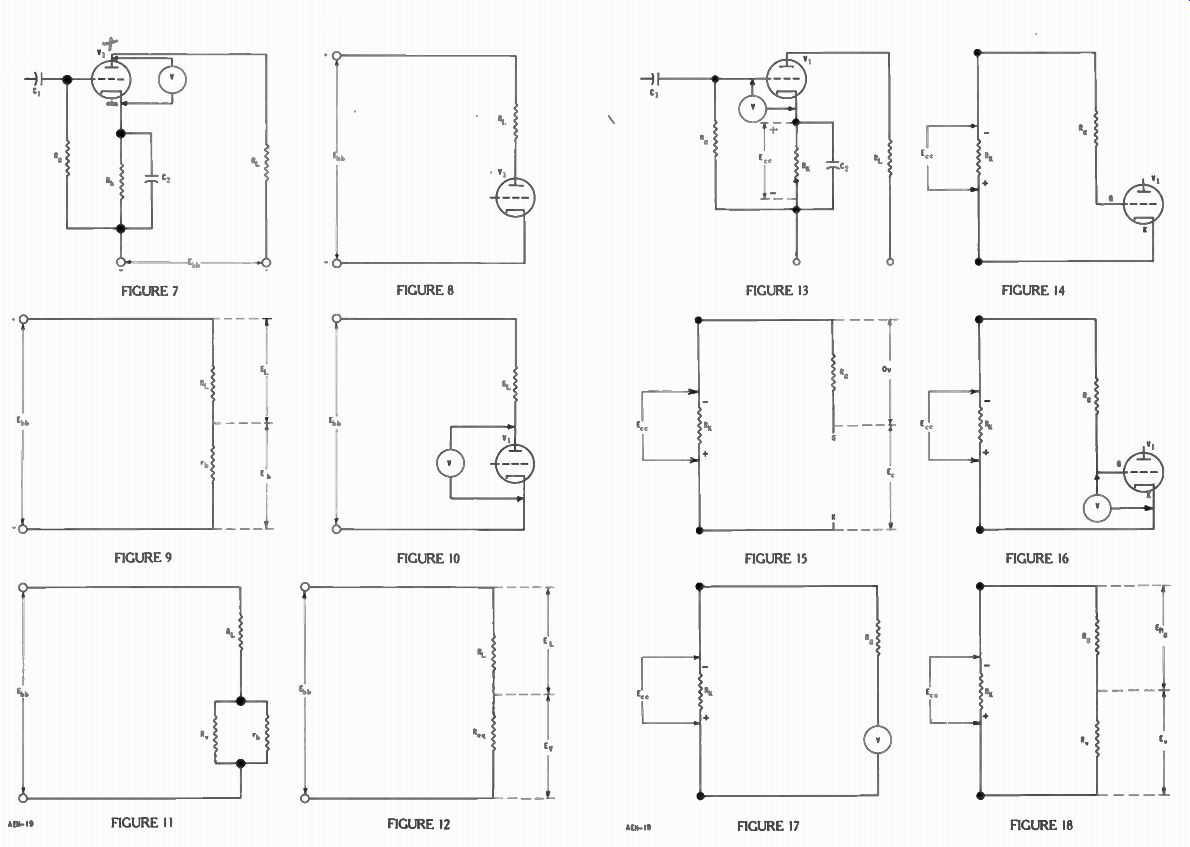
Errors are obtained also when meters are connected to measure voltage. Often, these errors are considerably greater than the am meter errors explained above. Figure 7 shows a triode employed as an amplifier. Here, C1 and R, are the input coupling components by means of which the signal is applied to the grid-cathode circuit of V1. In the plate circuit, the out put signal is developed across load resistor RL, Rk and C2 provide cathode bias for the tube.
The plate supply voltage Ebb is applied to the terminals of the plate circuit as indicated.
When checking the operating voltages in a circuit like that of Figure 7, it is normal practice to touch the voltmeter prods to the plate and cathode of the tube, as shown. All tube voltages are measured using the cathode as the reference point. Therefore, in the Figure, the voltmeter is measuring the plate voltage. As the plate is positive with respect to the cathode, the positive meter terminal is connected to the plate of V1 , and the negative terminal to the cathode. These connections provide an added current path through the meter, external to the tube. Electrons flow from the cathode through the meter to the plate without passing through V1 . This current operates the meter, and the pointer deflects to indicate the plate voltage. It is this conduction by the meter which causes the error.
In Figure 8, the plate circuit of V1 is redrawn to show that Ebb, is applied to RL and V1 in series.
Compared with RL and V1 , cathode resistor RK has very low resistance. For this reason, we have omitted Rk , and its bypass capacitor C. in Figure 8. Tube V1 conducts plate current in the direction from cathode to plate, and in this respect, may be considered a resistor. Therefore, we have re drawn the plate circuit again in Figure 9 where V, is replaced by the resistor labeled r b. Here, we have a series circuit like that of Figure 3. Voltage Ebb is across both R1 . and r b. The portion of this voltage across Ri , is labeled EL, and the remainder, across r b , is the plate voltage E,. As in all series circuits, E,, is equal to EL E,,. Therefore, the plate voltage is the difference between E,, and the voltage EL across the load resistor. That is, Eb = Ebb – E1.
Figure 9 represents the conditions without a meter connected to the circuit.
The plate circuit arrangement of Figure 8 is repeated in Figure 10 where voltmeter V is connected to measure the plate voltage of V,. Since the voltmeter conducts current, it can be represented as a resistor also. In Figure 10, the voltmeter and tube V1 are in parallel with each other. Therefore, these units are represented by resistors R. and r b , respectively, in Figure' 11. Here, load resistor Ri , is in series with the parallel circuit consisting of R. and r b.
Equation (4) can be employed to calculate the equivalent resistance of the two parallel units.
Thus, R. X rt.
R., = Rv+ rb
In Figure 12, this equivalent resistance is represented by resistor Req . Again, E, is the voltage across R,,, but the voltage across R,.„ is indicated as Ey, since this is what the voltmeter scale reads.
As explained for parallel circuits, the equivalent resistance is less than that in any branch.
Therefore, 11,.„ in Figure 12 is less than r b. As a result, the voltage Er indicated by the meter is less than the voltage Eb of Figure 9.

------------ This popular type radio receiver contains a number of series
circuits, parallel circuits, and combination circuits. Courtesy Crosley Div.
of Avco Mfg. Corp.
To illustrate how this error comes about, we can employ typical voltages and resistances as an example.
In the circuit of Figure 7, suppose E,,,,=250 volts, R1 ,== 100,000 ohms, and the plate current I b is .001 ampere. This current is carried by R1 . , therefore we can use Ohm's Law to calculate the voltage EL, indicated in Figure 9.
E, = I., x Ei.=.001 x 100,000= 100 volts.
Subtracting EL from the total applied voltage Ebb gives the actual plate voltage E,, which is present when there is no meter connected:
Eb= Ebb - El.
Eh= 250 - 100=150 volts.
Suppose a 1,000 ohms-per-volt meter is set to its 250 volt range to measure the plate voltage as shown in Figure 10. The meter resistance R, is equal to 250 x 1,000=250,000 ohms. With Eb= 150 volts, and .001 ampere, the resistance r,, presented by the tube is:
E., 150
=-=-= 150,000 ohms.
1,, .001 With and r,, in parallel, as shown in Figure 11, they have an equivalent resistance of, x rt.
In the circuit of Figure 12, the total resistance of R1 , and R,.,, in series is R.,.= Ri , + R.,.„= 100,000 + 93,750 = 193,750 ohms. The current in the circuit is increased to Ebb 250 I= = -.0013 ampere.
With this larger current in the load resistor, the voltage EL is equal to = Ix R. = .0013 x 100,000=130 volts.
Subtracting EL from Ebb gives the voltage E,. in Figure 12.
E,= ELL, - = 250 - 130 = 120 volts.
As Ev is the voltage that the voltmeter indicates, the meter reading is 120 volts, since this is the voltage across the tube with the meter connected as in Figure 10. As explained, the actual plate voltage without the meter connected is 150 volts. Therefore, connecting the meter to the circuit, in this example, results in an error of 30 volts.
Summarizing this action briefly, touching the voltmeter test prods to the plate and cathode of tube V, in Figure 7 results in an equivalent resistance between the points of connection which is less than the resistance of the tube alone. The total resistance of the plate circuit thereby is reduced, allowing the circuit current to in crease. With the larger current, the voltage EL across the load resistor is greater. As the applied voltage Ebb is unchanged, there is less of this voltage available to appear across the tube, since the plate voltage Eb is equal to Ebb - EL. As mentioned, it is common practice to measure plate voltage in the manner shown in Figure 7, even though we know the reading obtained is not exactly correct.
When such a measurement is made therefore, it is necessary to keep in mind the fact that the actual voltage present is somewhat higher than indicated by the voltmeter scale. If the voltmeter had in finite resistance, it would not decrease the resistance of the circuit to which it is connected. Then, Rer, in Figure 12 would be equal to r, in Figure 9, the circuit currents and EL would be the same in both cases, and Ev would be equal to E,. To approach this ideal condition with a given voltmeter, it is a good idea to EMPLOY THE HIGHEST VOLTAGE RANGE WHICH WILL PERMIT REASONABLY EASY READING OF THE SCALE. To illustrate the smaller error obtained when a high resistance voltmeter is employed, suppose a vacuum tube- voltmeter is connected to measure the plate voltage as shown in Figure 7. If the VTVM has an input resistance of 10 megohms, then, in Figure 11, Rv and r, have an equivalent resistance of
R„ - X rb 10,000,000 x 150,000 10,000,000 +150,000 1,500,000,000,000 R„- 147,783 10,150,000 or approximately 148,000 ohms.
In the circuit of Figure 12, the total resistance is RT = RL + Reg = 100,000 ± 148,000 = 248,000 ohms. Therefore, the current in the circuit is Ebb I - Rr 248,000 250 .001008 ampere.
With this current in Rt ., the voltage across this resistor is:
E. =I x R, =- .001008 X 100,000 = 100.8 volts.
Subtracting E1 . from E„,, gives the voltage indicated by the meter E, = Ebb - = 250 - 100.8= 149.2 volts.
Since the plate voltage without the meter connected is 150 volts, this meter reading of 149.2 volts is ch more accurate than that obtain with the 1,000 ohm-per volt met r.
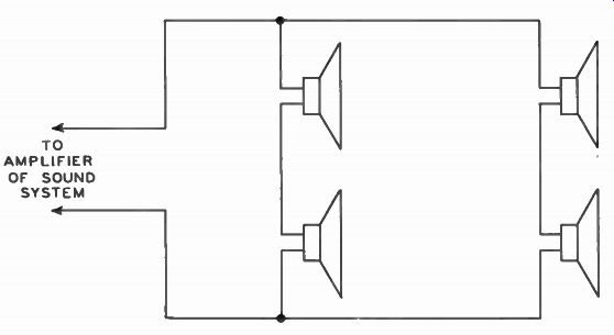
-------------- In certain public address systems the loudspeakers are operated
as a combination circuit to provide proper sound coverage.
Figure 13 shows a voltmeter V connected to measure the bias voltage between the grid and cathode of an electron tube. In this circuit, the cathode bias voltage E„ is developed across the cathode resistor, R is., with the polarity indicated. This Figure illustrates one method sometimes employed to measure the grid bias.
However, due to the normal grid cathode circuit conditions, a volt meter connected as shown provides a reading with considerable error, unless the meter resistance is very high.
To explain the cause of this error, we have redrawn the grid cathode circuit in Figure 14. Here, the cathode bias voltage Ec , is represented as the applied voltage with polarity such that the upper terminal is negative, and the low er terminal positive. By careful inspection, you will see that this circuit is exactly like the grid cathode circuit of Figure 13, insofar as electric connections are concerned.
In Figure 14, there is a conductive path from the negative terminal of R. through the grid resistor R. to the grid of V. The cathode is connected directly to the positive terminal of R.. There fore, the cathode bias voltage E„ is applied to Rg and the grid-cathode portion of V1 in series. How ever, when the tube is operated so that there is no grid current, the resistance between the cathode and grid within the tube can be considered infinite. Thus, there is NOT a complete circuit through the tube and R.. This condition is illustrated in Figure 15.
Here, the tube has been re moved entirely to show that it does not provide a path for current in the grid circuit.
With no current in R., there is no voltage across this resistor, as indicated. With no difference of potential across R„ both of its terminals are at the same potential. Therefore, point G in Figure 15 is at the same potential as the negative terminal of resistor R.. Also, point K is at the same potential as the positive terminal of R.. Thus, points G and K, the grid and cathode of VI, have a difference of potential E, equal to E„. This situation exists when there is no meter connected to the grid and cathode.
Figure 14 is repeated in Figure 16, but now a voltmeter V is connected to measure grid bias voltage in the manner of Figure 13, and the meter provides a conductive path between points G and K. Therefore, now a current path exists from the lower terminal of R. to the positive terminal of R.. Again we do not show the tube in Figure 17, since only the meter V forms a complete series circuit with R.. In Figure 18, resistor Rv represents the meter resistance, and with a circuit thus completed, the applied voltage E„ causes current in R and R. With current in this circuit, there is a voltage E.s across the grid resistor and a voltage Ev across the meter as indicated.
As in all series circuits, the applied voltage is equal to the sum of the voltages across the individual components. Thus, in Figure 18, E„.=Elie+E%.
Hence, the voltage Ev indicated by the voltmeter is equal to the difference between the applied voltage E„ and the voltage ERg : Er L---E„-Eng Therefore, because the current allowed by the voltmeter produces a voltage across the grid resistor R,, the voltage Ev indicated on the meter is less than the actual bias Ee.
Using typical circuit values in an example, suppose the circuit of Figure 13 operates with an applied bias E„.= -5 volts, and the grid resistor R, has a resistance of 1,000,000 ohms. As explained for Figure 15, with no voltmeter connected, the full bias voltage appears between points G and K. That is, the grid bias E, on V1 is 5 volts negative with respect to the cathode.
Suppose a 1,000 ohms-per-volt meter, set to its 10 volt range, is connected to measure the grid voltage as in Figure 13. The meter resistance then is 10 x 1,000 =10,000 ohms. As explained for Figures 16 and 17, the meter completes the circuit between the grid end of R, and the cathode end of R. In Figure 18, the grid resistor and meter form a series circuit which has a total resistance R, equal to: L=1,000,000+10,000=1,010,000 ohms.
Applied to this series circuit, the voltage E,„ produces a current equal to:
5 RT 1,010,000
.00000495 ampere.
With this current in the circuit, the voltage Ev indicated by the voltmeter is: Ev=IxEr = .00000495 x 10,000 = .0495 volts, or approximately .05 volts.
Thus, the meter reading is only .05/5, or 1/100, of the actual bias present when the meter is not connected. With the voltmeter in the circuit, practically all of E, appears across the grid resistor.
Thus: Eng =IxR, Eng = . 00000495 x 1,000,000= 4.95 volts.
As when measuring plate voltage, less error is obtained if a high resistance voltmeter is employed to measure grid voltage in the manner of Figure 13. For ex ample, suppose the meter used is a vacuum tube voltmeter with an input resistance of 10 megohms.
In this case, in Figure 18, R. and It,. have a total resistance of RT=RG+Rv 11-, =1,000,000+10,000,000 =11,000,000 ohms.
In this series circuit, the applied voltage E,, produces a current of E„ 5 I= .00000045 amp.
RT 11,000,000 and the voltage indicated by the meter is Ev=lx1tv E= .00000045 x 10,000,000 =1.5 volts.
Thus, even with the higher resistance meter, an appreciable error is obtained when the connection of Figure 13 is employed to measure grid bias.
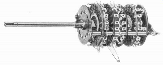
---------- In many electron instruments, multi-terminal switches, operated
by a common shaft, ore mounted to form a single unit as shown here. These switches
permit changing connections in several combination circuits at the some time.
Courtesy Oak Mfg. Co.
As explained for Figures 14 and 15, the voltage between the grid and cathode is equal to E„, and this voltage is also across the cathode resistor R. Therefore, to measure the grid bias in a circuit of this type, the voltmeter may be connected across the cathode resistor. The test lead from the ( 4- ) meter terminal is touched to the positive end of RK, and the lead from the ( - ) meter terminal to the negative end of RK. The grid to cathode measurement is used as a rough check to make sure that the voltage applied to the grid isn't positive and close enough to the cathode resistor voltage to indicate a good grid resistor.
Referring again to Figures 7 through 12, when the meter resistance is 250,000 ohms, the reading obtained is in error by 30 -X100=20%. 150 When the VTVM is used with a 10 megohm input resistance, the per cent of error is only .8 -x100=0.53%. 150
In the case of Figure 13 through 18, when the meter resistance is 10,000 ohms, the meter reading is in error by 4.95 -X100=99%. 5 and with the 10 megohm input resistance of the VTVY, the error percentage is .5 - X100=10%. 5
These percentages show two things:
(1) for a given circuit, the higher the meter resistance, the more accurate the reading.
(2) For a given meter, greater accuracy is obtained when the meter resistance is high compared with that of the circuit component in parallel or series with the meter.
Generally, it is considered that sufficient accuracy is obtained for most practical purposes when a voltmeter has resistance at least 10 times that of the resistance of the component which the meter is connected in parallel or in series with. In Figure 11, the meter resistance R, is connected in parallel with the resistance r b of the tube. In Figure 18, the meter resistance R. is connected in series with the grid resistor It,. Thus, Rv should be at least 10 times rb or R, for these two examples.
RESISTOR COMBINATION CIRCUITS
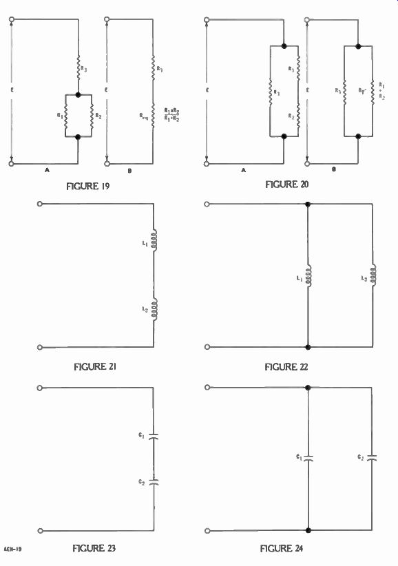
Referring to Figure 11, resistors R, and r b are connected in parallel. As explained, these parallel units are represented in Figure 12 by a resistor R, equal to their equivalent resistance. How ever, R,.„ is in series with RI. Therefore, the circuit of Figure 11 is not a parallel circuit only, nor is it just a series circuit; it is a combination of both. Consequently, a circuit of this type is called a combination circuit. In this case, we produced a combination circuit by connecting a volt meter in parallel with an electron tube. This arrangement is only one example of a general form which is shown in Figure 19A. Here, we show resistors R1 and R, in parallel, and this parallel section of the circuit is in series with resistor R3.
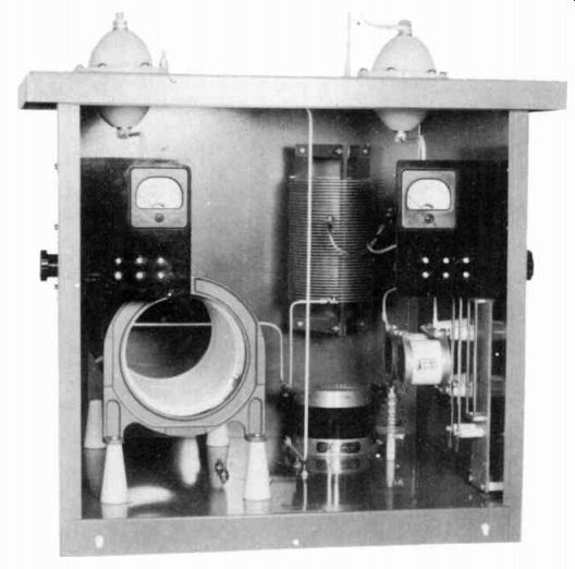
--------------- Antenna tuning unit uses inductors in series and parallel
circuits. On the upper coil, the tap can be adjusted to vary the inductance
to the desired value. Courtesy Collins Radio Co.
In the various electron circuits to be studied, you will encounter many more combination circuits like that of Figure 19A. However, should you desire, you can use the method we employed with Figures 11 and 12 to convert this type of combination circuit to a simple series circuit like that of Figure 19B. That is, in Figure 19A, the resistances of R1 and R. can be substituted in equation (4) to give 11,.„ of Figure 19B. Since Figure 19B is a series circuit, all the rules and conditions apply to it which were explained for Figure 2.
Figure 18 is an example of an other type of combination circuit.
Resistors R, and R. form a series circuit, and this series circuit is in parallel with resistor R.. Again, we produced the combination circuit of Figure 18 by connecting a voltmeter to an electron tube circuit. However, as you advance in your studies, you will en counter many more combination circuits of this type also. The general form is shown in Figure 20A. Here, resistors R1 and R. in series form one branch of a parallel circuit. It, is the other branch. When ever you desire, you can substitute the resistances of R1 and R. in equation (1) to obtain R/ of Figure 20B. As the circuit of Figure 20B is a parallel circuit, all the rules and conditions apply to it which were explained for Figure 5. Thus, together with Ohm's Law, the four equations given in the earlier sections of this lesson provide you with means of computing voltage, current, and resistance in any circuit composed of resistors, regardless of whether the resistors are connected in series, in parallel, or in a combi nation circuit.
Often, when solving problems concerning combination circuits, you will find that you cannot obtain the values desired directly from the information given. In such cases, the best plan is to study the circuit carefully and decide exactly what additional in formation you need in order to use some equation that will give you the voltage, current, or resistance desired. Then, you begin by using the given data in one or more equations which will give the additional information need ed. With this information thus obtained, you can complete the solution of your problem. Stated briefly, several steps are generally required to solve problems dealing with combination circuits.
As an example of this procedure applied to the circuits of Figures 19A and 20A, suppose, in both of these circuits, the applied voltage E is 100 volts, R1 =20 ohms, R. is 30 ohms, R, is 8 ohms, and we desire to know the current in R2 in Figure 19A, and the voltage across R. in Figure 20A. For Figure 19A, we can use Ohm's Law in the form I.= E2,/lt, to find the desired current. How ever, to do so, we need to know the voltage E. which is across R2.
This voltage E, is across both branches of the parallel section.
If we determine the equivalent resistance R,. of R1 and R2 in parallel, and the circuit current I, we can compute the voltage E. from Ohm's Law in the form E2 =I x R„,. Since the values of R, and It, are given above, we first use equation (4) to find R„,: xR, 20 x 30 600
---=-=12 ohms.
Ri+lt, 20+30 50
This step changes the circuit to the simple series arrangement of Figure 19B. Now, we can use equation (1) to find the total resistance of this circuit:
Itt=Ri+FL.=8+12=20 ohms.
Since the applied voltage is 100 volts, we can use Ohm's Law to find the circuit current I: E 100 I=-=-=5 amperes.
Next, we can use Ohm's Law to find the voltage across R„, in Figure 19B. However, since R,.„ rep resents the parallel resistors R1 and R. in Figure 19A, the voltage across R,.„ is also the voltage E2 across R.. Thus: E,=IxR=5x12=60 volts.
Finally, we use Ohm's Law to obtain the current in R2 E2 60 I=-=-=2 amperes.
R, 30 To find the voltage across R2 in Figure 20A, we can use Ohm's 1_ = RT Law in the form E2 = 12 X R2P where I., is carried by the R1, R2 branch of the circuit. Since the voltage E is applied across R, and R. in series, we can find I_2 by using Ohm's Law in the form I2 E/RT, in which RT is the total resistance of the series resistors R, and Ro. Since the resistances of R1 and Ro are given, we first use equation (1) to find RT: RT= Ri+lt,=20 +30 = 50 ohms.
This step changes the circuit to the simple parallel arrangement of Figure 20B. Next, we use Ohm's Law to find the current in Ri -. Since 11, represents the series resistors R1 and Ro in Figure 20, the current in RT is also the current I_2 in R2. Thus: E 100 =-=2 amperes.
Finally, we use Ohm's Law to obtain the voltage across Ro: E,= I, x 11,= 2 X 30 = 60 volts.
SERIES INDUCTORS
Two independent inductors are shown connected in series in Figure 21; that is, there is no magnetic coupling between them.
When such inductors are connected in this manner, the total inductance of the circuit is the sum of the individual inductances. This rule is the same as that for series resistors. Stated as an equation: LT=Li+1, (5)
Thus, if L1 is 8 henrys and L., is 4 henrys in the circuit of Figure 21, the circuit has a total inductance of: LT=8+4=12 henrys.
Also, as in resistor circuits, the voltages across the series inductors are directly proportional to the individual inductances, and their sum is equal to the applied voltage.
PARALLEL INDUCTORS
Two independent inductors parallel connected are shown in Figure 22. Again, the rule for the inductance presented by the en tire circuit is the same as with resistors. That is, the equivalent inductance of two inductors in parallel is equal to the product of the individual inductances divided by their sum. As an equation: L1 x 1,2 L L1+L2 (6)
Thus, if L1=15 henrys and L2 =10 henrys in Figure 22, the circuit presents an equivalent inductance of: 15 x10 150 L.q = 6 henrys.
As with resistors, the inductance of the entire parallel circuit is less than the inductance in any branch.
A voltage applied to the terminals of the circuit of Figure 22 is applied to both L, and L2. Thus, in any parallel inductance circuit, the voltage across each branch is equal to the applied voltage. Also, the branch currents are inversely proportional to the branch inductances, and the total current equals the sum of the branch currents.
Again these situations are the same as in resistor circuits.
SERIES CAPACITORS
A series circuit made up of two capacitors is shown in Figure 23.
As you may recall, the nearer the plates of a capacitor are to each other, the greater the capacitance.
Connecting capacitors in series has the same effect as moving the plates of a single unit farther apart. That is, it decreases the capacitance. A series capacitor circuit has an equivalent capacitance which is less than the capacitance of the smallest capacitor.
The equation for computing the equivalent capacitance of two capacitors in series is like that used for two resistors in parallel. Thus, for a circuit like that of Figure 23: C1 X C2 C„- Ci+C2 (7)
For example, if C1 -..002 and C2= .003 id, then the equivalent capacitance of these capacitors in series is:
.002 x .003 .000006 Ceq = .0012 µf.
.002+ .003 .005
PARALLEL CAPACITORS

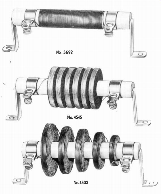
-------------- On these wire-wound resistors, the adjustable bands provide
a third terminal, and often connections are made so that part of the resistor
becomes a branch of a parallel circuit which is in series with the remainder
of the resistor. Courtesy Ohmite Mfg. Co.
With a given spacing between them, the larger the plates of a capacitor the greater its capacitance. Connecting capacitors in parallel has the same effect as in creasing the area of the plates of a single unit. It increases the capacitance. Two capacitors connected to form a parallel circuit are shown in Figure 24. A circuit like this has a total capacitance equal to the sum of the capacitances of the individual capacitors. The equation is like that for series resistors: CT=n+C: (8)
To illustrate the use of equation (8) for the circuit of Figure 24, suppose C,..001 ef and C2 = .005 ,d. Then the total capacitance of the circuit is:
CT = + =•001 + .005 = . 006
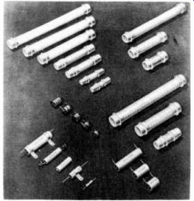
--------- These ceramic tubular capacitors are a type commonly found
in the circuits of television and radio receivers as well as many other electron
instruments. Courtesy Centrolab Division of Globe Union, Inc.
VOLTAGES ACROSS CAPACITORS
When a voltage E is applied to the terminals of the circuit of Figure 23, it produces electron flow which charges the capacitors. For example, if E has polarity such that the upper terminal is made positive and the lower terminal negative, electrons flow from the voltage source to the lower plate of C., from the upper plate of C. to the lower plate of C1 , and from the upper plate of C1 to the voltage source. Since the electrons do not pass through the capacitors, they "accumulate" on the lower plates to produce a negative charge on these plates. Also, as the electrons leave the upper plates, the electron "deficiency" produces a positive charge here.
Electron flow in this manner is known as "displacement current." Due to its plates having obtained opposite charges, each capacitor has a voltage across it. As in all series circuits, the electron flow is the same in every part of the circuit. Therefore, in Figure 23, both capacitors receive the same charge. For any capacitor, the voltage across its plates is equal to the number of electrons displaced measured in coulombs divided by its capacitance in far ads. Thus, in Figure 23, where Q represents the number of coulombs in the charge, the displaced electrons produce a voltage on capacitor C1 equal to: E,=-, C, and a voltage on capacitor C. equal to: E.,=
As an example, suppose a voltage E is applied to the terminals of the circuit of Figure 23 such as to cause a charge Q of .0036 coulombs to be produced on each capacitor. If C1.20 id, the voltage across this capacitor is: Q .0036
-180 volts.
C1.00002
If C.= 30 t tf, the voltage across this unit is: Q .0036 -120 volts.
Notice here that the voltage E1 across the 20 4 capacitor is greater than the voltage E, across the 30 4 capacitor. This condition exists whenever capacitors are connected in series. That is, IN A SERIES CIRCUIT, VOLTAGES ACROSS THE CAPACITORS ARE INVERSELY PROPORTIONAL TO THE INDIVIDUAL CAPACITANCES. This relation is exactly opposite that found in series resistance and series inductance circuits.
As in all series circuits, the sum of the voltages across the capacitors in Figure 23 is equal to the total voltage applied to the terminals of the circuit. There fore, to produce the voltages E1 and E, calculated in the above ex ample, the voltage applied to the circuit must be equal to:
E= E.+ E., E 180 + 120 = 300 volts.
When a voltage E is applied to the terminals of the circuit of Figure 24, this voltage is applied to both capacitors. Each capacitor is a branch of the parallel circuit.
The applied voltage produces a displacement of electrons in each branch which charges the capacitors in the manner explained above. When the capacitors are charged, voltage E1 across C1 and voltage E2 across C2 are both equal to the applied voltage E, and therefore to each other also.
As in all parallel circuits, the total electron flow supplied from the source is equal to the sum of the electrons displaced in the branches of a parallel capacitor circuit. Therefore: 14=11+12 For example, if 300 volts is applied to the terminals of the circuit of Figure 24 in which C1 = 20 4 and C, = 30 4, the voltage E, E =300 volts, and the charge on C1 is: Q1=CL x E1= .00002 x 300 = .006 coulombs.
Also, the voltage E2 = E .300 volts, and the charge on C2 is: Q2 = C2 X E2=.00003 x 300 = .009 coulomb.
Here, as in all parallel capacitance circuits, the branch with the largest capacitance has the largest displacement current.
That is, the branch currents are directly proportional to the branch capacitances.
Since current in amperes is the total number of electrons that flow each second measured in coulombs, if both capacitors are charged in 1 millisecond of time, the displacement current in the C1 branch is: C1, .006 t .00t and that in the C., branch is:
.009 I=-=-=9 amperes. t .00t
Equal to the sum of these displacement currents, the total current supplied by the source to charge the capacitors is: I, =I L -02= 6+9=15 amperes.
The circuit principles outlined in this lesson form the foundation upon which you can base your analysis of the various practical circuits which may be encountered in service and maintenance work. Most electron equipment is made up of nothing more than series circuits, parallel circuits, and combination circuits.
SUMMARY
In all series circuits, the sum of the voltages across the individual components, is equal to the applied voltage. In those made up of resistors or inductors, the component voltages are directly proportional to the individual resistances and inductances. In capacitor series circuits, the capacitor voltages are inversely proportional to the capacitances. In all series circuits, the current is the same in all parts of the circuit.
In all parallel circuits, the total current is equal to the sum of the branch currents. In the resistor and inductor circuits, the branch currents are inversely proportional to the branch resistances and inductances. In the case of capacitor parallel circuits, the branch currents are proportional to the branch capacitances. In all parallel circuits, the voltage is the same across all branches and equal to the applied voltage.
The various equations given for computing resistances, inductances, and capacitances have a form which states that the total circuit value is equal to the sum of the individual values in the case of:
1) resistors in series
2) inductors in series
3) capacitors in parallel, and a form which states that the equivalent circuit value for two components is equal to the product of the individual values divided by their sum in the case of:
1) resistors in parallel
2) inductors in parallel
3) capacitors in series
The explanations regarding voltmeter error were given to illustrate the actual conditions encountered when you are troubleshooting electron equipment.
APPENDIX A
EQUIVALENT RESISTANCE OF PARALLEL RESISTORS
In this lesson, equation (4) is given as, R,.„ = x R R. . This equation applies to parallel circuits containing two resistors. only, and is a special form of a more general equation for circuits with any number of resistors in parallel. This general equation is derived as follows: Assume a parallel circuit composed of a number of branches having resistances R1 , 112, R3 and so on. If a voltage E is applied to the terminals of this circuit, each branch carries a current, and the sum of these branch currents is the total circuit current I. Thus: I_T=I1+I2+I3
Since the voltage across each branch is equal to E, branch current I1 = E/RI, branch current I2 = E/110, and so on. We can substitute these E/R terms for I1 , I ?, etc. in the above expression to give:
EEE I T=-+-+-+ • • • R1 Rs
By Ohm's Law, the total current I T is equal to the applied voltage E divided by the equivalent resistance R„, of the circuit: E I T = R" Therefore, as they are both equal to I T, the right members of these equations are equal to each other: E EEE
Factoring out the E in the right member, we can write this expression as:
APPENDIX A-(Continued)
Dividing both members of this equation by E, we obtain the general equation for R..„ which may be applied to a parallel circuit with any number of branches:
For two branches, the above equation is written as:
To simplify the right member, we can multiply the numerator and denominator of the first term by Ro, and the numerator and denominator of the second term by R1 , thus obtaining a common denominator:
Adding the terms of the right member gives:
Inverting both members, we have:
R1 X R2 Lq- + k which is the form shown for equation (4) in this lesson.
As for resistor circuits, there are general equations for parallel inductor circuits and for series capacitor circuits which are derived in a manner similar to that for Re<,.
These general equations are: 1 1 1 1
For parallel inductors:
L., L1 L2 L3 For series capacitors: 1 1 1 1
C. ‹ , C1 Ca C3
ESSENTIAL SYMBOLS AND EQUATIONS
- equivalent capacitance (farads)
CT - total capacitance (farads)
C1 , C2 - individual capacitances (farads)
E - applied voltage (volts)
E1 , E2 - individual voltages (volts)
I T - total current (amperes)
I_2 - individual currents (amperes)
- equivalent inductance (henrys)
LT - total inductance (henrys)
L1 , L2 - individual inductances (henrys)
- equivalent resistance (ohms)
RT - total resistance (ohms)
R1, R2 - individual resistances (ohms)
RT R1+ R2 (1)
E = Ei+E2 (2)
I T = Il1+I2 (3)
RIXR2 Re , - +R2 (4)
LT -= L1 + L2 (5)
L1 X L2 Leg + L2 (6)
CIXC2 = C1 +C2 (7)
CT C1 +C2
(8) ESSENTIAL SYMBOLS AND EQUATIONS
- equivalent capacitance (farads)
CT - total capacitance (farads)
C1 , C2 - individual capacitances (farads)
E - applied voltage (volts)
E1 , E2 - individual voltages (volts)
I_T - total current (amperes)
I_2 - individual currents (amperes)
- equivalent inductance (henrys)
LT - total inductance (henrys)
L1 , L2 - individual inductances (henrys)
- equivalent resistance (ohms)
RT - total resistance (ohms)
R1, R2 - individual resistances (ohms)
RT R1+ R2 (1)
E = E1+E2 (2)
I T = I1 +I2 (3)
R1XR2 Re , - +R2 (4)
LT -= L1 + L2 (5)
L1 X L2 Leg + L2 (6)
C1XC2
= C1 +C2 (7)
CT C1 +C2 (8)
WORK DIAGRAM SOLUTIONS
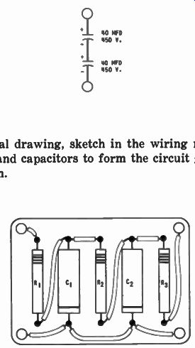
1. A 20 ufd, 600 volt capacitor is needed. The only units available are rated at 40 ufd, 450 volts. Draw a schematic diagram showing how two of the available capacitors can be connected to satisfy the stated requirements. Indicate the capacitor positive and negative plates.
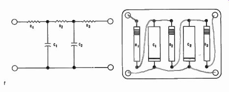
2. In the pictorial drawing, sketch in the wiring needed to connect the resistors and capacitors to form the circuit given in the schematic diagram.
------------
-----------
------------
------------
FROM OUR NOTEBOOK
THE MAN WHO STICKS
The man who sticks has this lesson learned;
Success doesn't come by chance--its earned
By pounding away; for good hard knocks
Will make steppingstones of the stumbling blocks
He knows in his heart that he cannot fail,
That no ill effects can make him quail
While his will is strong and his courage high,
For he's always good for another try.
He doesn't expect by a single stride
To jump to the front; he is satisfied
To do every day his level best,
And let the future take care of the rest.
He doesn't believe he's held down by the boss -- It's work, and not favor, that "gets across",
So his motto is this: "What another man
Has been able to handle, I surely can",
For the man who sticks has the sense to see
He can make himself what he wants to be,
If he'll off with his coat and pitch right in--Why, the man who sticks can't help but win!
-Charles R. Barrett
Yours for success,
-DIRECTOR