AMAZON multi-meters discounts AMAZON oscilloscope discounts
INTRODUCTION
Industry’s desire to increase productivity has been the main catalyst for increased automation. This automation is used to control not only individual machines but an entire process. A control system must consider input information, output, and the processing itself.
As early as the late 1960s, manufacturers tried alter natives for control circuits. Minicomputers were used, but they were not designed for industrial life, they had no input or output capabilities, and they generally had to be programmed in assembly or machine language.
The evolution to programmable controllers from standard or conventional minicomputers occurred through the late 1960s and early 1970s. Some credit General Motors with initially conceiving the programmable controller in 1968. Engineers at Cincinnati Mila cron also worked on the development of a programmable controller. The early programmable controllers had to meet the following requirements:
1. Easily programmed and reprogrammed
2. Easily maintained
3. More reliable
4. Physically small
5. Capable of handling data communication
6. Cost competitive
7. 115 V AC input/output
8. Expandable in size and memory
Although the shutdown times were reduced because reprogramming was less time consuming than with traditional hard-wired methods, there were still some major problems with these early programmable controllers. The programming language was still very complex and required training in programming to understand. The first units were very large and costly and did not save floor space.
During the development phase of computer-con trolled systems, the only desire was to have a method of replacing magnetic relays. The introduction of the microprocessor in 1978 led to smaller, faster, and less expensive computers. These new designs brought improvements to the programmable controller and made it what it is today. In order for programmable controllers to be used by persons knowledgeable in ladder diagrams and relay logic, several manufacturers use high-level programming languages based on more conversational style. These languages include PROTEUS from Westinghouse, BICEPS from Honeywell, and PCL from Hitachi. Unfortunately, some of these high-level languages are still implemented only on mainframes and minicomputers.
PROGRAMMABLE CONTROLLER
The programmable controller is defined by the National Electrical Manufacturers Association as a digitally operating electrical apparatus that uses a programmable memory for the internal storage of instructions for implementing specific functions such as logic, sequencing, timing, counting, and arithmetic to control machines or processes through digital or analog input or output modules. A digital computer used to perform the functions of a programmable (logic) controller is considered to be within this scope. Excluded are drum and similar mechanical-type sequencing controllers. The definition of a programmable controller as a replacement for solid-state logic controls or electromechanical relay controls must also indicate that it can be programmed or reprogrammed and maintained by persons unskilled in the use of computers. A person who is already knowledgeable in relay logic systems should be able to master most programmable controller functions in a few hours.
A programmable controller system controlling a simple process may be housed in one or more units. For a more complex process, the entire system may consist of three to five or more units connected together. Connecting these units together is relatively simple and is usually done with single cables. The connections for the input and output modules present a still more complex task. The overall programmable controller system al ways consists of the following: the CPU (central processing unit), the programmer/monitor, and the input/ output modules; it may include peripherals such as a printer and a program recorder/player. FIG. 1 shows a block diagram representation of a programmable controller.
A CPU is a computer centered around a single microprocessor chip. Its operation is similar to a desktop or personal computer, although it is generally limited to industrial control applications, whereas a personal computer would be used for all kinds of personal productivity. The CPU includes the microprocessor, fixed memory, alterable memory, and usually the power sup ply. A typical programmable controller is shown in FIG. 2. Although the input and output modules are included, the keyboard and the display unit are not shown. They are not required for the operation of a programmable controller, but are necessary only for the actual programming steps.
The input modules receive either binary or analog signals provided by transducers. In early programmable controllers, only digital or binary inputs were used. This provided only ON/OFF control. However, today it is not uncommon to use programmable controllers that provide proportional, integral, and derivative (or PID) control. FIG. 3 shows standard input modules.
Transducers
Various instruments are used to measure variations in temperature, pressure, current, or other variables. These variable measurements can be changed into electrical impulses. Another variable that is often measured is position. The measurement of position can be either absolute or incremental. Absolute transducers measure position with respect to a fixed or datum point. An incremental transducer measures distance moved from the last measured point. This would result in an inaccurate measurement after a power failure.
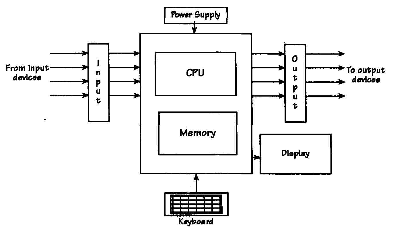
FIG. 1 Block diagram of a programmable controller.
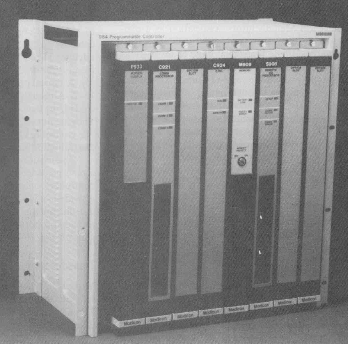
FIG. 2 Typical programmable controller with CPU, memory, power supply,
I/O slots, and communication processor. (Courtesy of Modicon, Inc.)
Proximity detectors may be defined as solid-state limit switches. FIG. 4 shows such a device. Many of these use optical detection for measurement. Measurement of weights is very important for economic and often legal applications. The simplest method for weight measurement is a balance arm with a known weight used to balance an unknown weight. A strain weigher requires a secondary transducer, which is used to measure the amount of deflection caused when a weight is measured by exertion of a force on a spring.
Devices are available to measure almost any vari able. To make these measurements in control circuits requires the use of transducers. In the strictest sense, a transducer is a device that converts one physical quantity into another. The term transducer is often used interchangeably with the sensor itself, rather than to refer to the complete process.
DESIGN USING PROGRAMMABLE CONTROLLERS
Keep in mind that ON/OFF control, although simpler than PID. should not be thought of as an inferior form of control. Many processes will require only ON/OFF control systems. The output from the output module might be used to actuate pumps, motors, pistons, relays, or other devices.
When programmable controllers are used in control circuits, the following design steps should be followed:
1. Define the process.
2. Sketch the operation using block diagrams or flow charts.
3. Give a written description of each step.
4. Show where sensors are required.
5. Show where manual controls, such as switches, are required.
6. Add master switches for stopping and starting the operation.
7. Consider fail-safe operation to protect personnel.
8. Draw a ladder diagram representing all steps of the operation.
9. Create a parts list of sensors, relays. and the like.
10. Create a wiring diagram showing the interconnection of various modules.
The final step should include a series of “what could go wrong” questions and what steps may be necessary to correct faults.
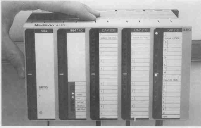
FIG. 3 Programmable controller with three standard input/output units.
(Courtesy of Modicon, Inc.)
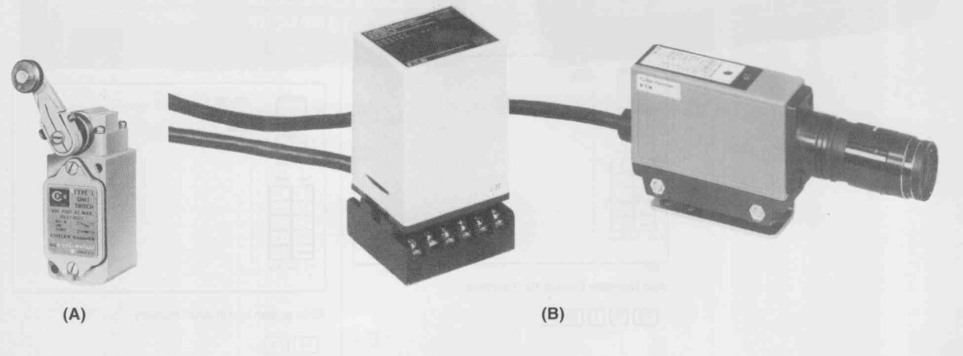
FIG. 4 (A) Simple limit switch and (B) proximity detector. (Courtesy
Eaton Corporation, Cutler—Hammer Products)
Programming the Programmable Controller
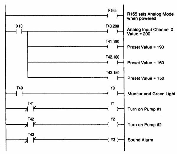
Once an operation has been fully described and documented, the programmable controller can be programmed. Each manufacturer may use a slightly different format for its programmable controller; however, the principles are the same for all types. Individual manuals will include the required screen format, numbering schemes, limitations, and other important information for each controller. A representative page from a manufacturer’s manual is shown in FIG. 5.
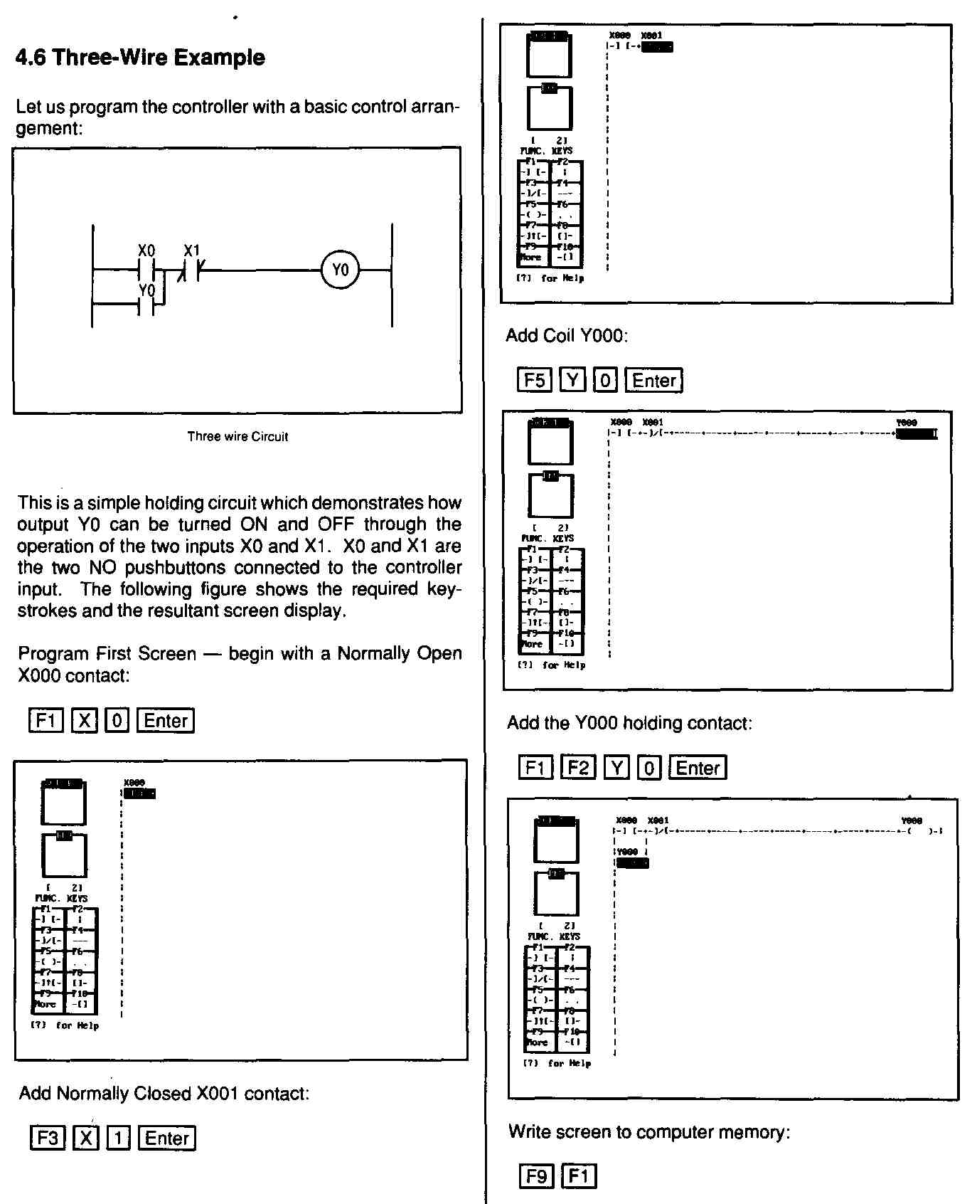
FIG. 5 Page from programmable controller manual demonstrating programming
steps and screen format. (Courtesy of Eaton Corporation, Cutler—Hammer
Products)
4.6 Three-Wire Example
Let us program the controller with a basic control arrangement:
Three wire Circuit
This is a simple holding Circuit which demonstrates how output YO can be turned ON and OFF through the operation of the two inputs XO and Xl - XO and Xl are the two NO pushbuttons connected to the controller input. The following figure shows the required key strokes and the resultant screen display.
Program First Screen — begin with a Normally Open X000 contact:
Add the Y000 holding contact:
Write screen to computer memory:
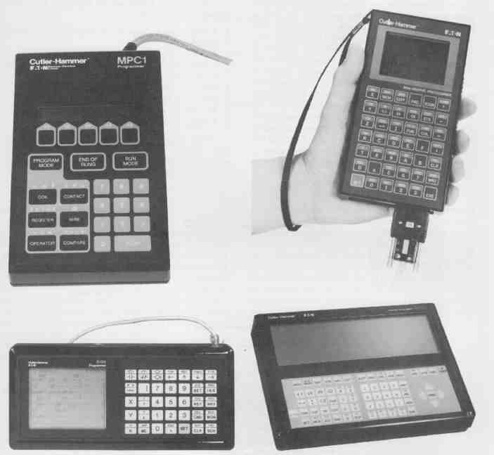
FIG. 6 Hand-held and small graphic programmers. (Courtesy Eaton Corporation,
Cutler—Hammer Products)
Major differences can be found between hand-held units and large monitor units. The large-monitor-type unit generally displays a number of ladder rungs at a time, whereas the hand-held unit may show only a portion of one or more rungs. Two types of controllers are shown in FIG. 6. There is a trade-off for the large- monitor type in cost factor and, although the view of the complete circuit is helpful during programming, it is of no use during operation. Some programmable controllers, with an appropriate interface, allow a standard microcomputer to be used as the keyboard and display unit for programming. Using a microcomputer only during the programming stage provides the advantage of a full-screen display without the cost associated with a large monitor dedicated only as an output display. The microcomputer can be used in other applications when not needed for programming the controller. Each programmable controller provides codes for incorrect programming or problems during operation. On a large screen, the error message may include the error code as well as some explanatory phrase. On a smaller unit, only the code may appear, requiring the operator to check the reference manual for a description of the error. For example, 24 might appear on the display of a small system; this number refers to a memory overflow, so the words memory overflow would probably appear on the screen of a large-monitor system.
Each programmable controller has format limitations that must be observed when programming ladder diagrams. If the format is not correct, the CPU will not accept the program into memory. FIG. 7 shows a page of error messages and what these messages might represent for a typical programmable controller.
The following limitations are typical for most programmable controllers:
1. A contact must always be inserted in the first slot of the first rung.
2. A coil or output must be inserted first.
3. A limited number of outputs and contacts can appear on the screen at one time.
4. Only one output can be connected to one contact.
5. Flow must always go from left to right.
6. All contacts must run vertically.
7. A coil or contact must be inserted last.
Some common relay symbols, including normally open contacts, normally closed contacts, and coils or outputs, are used no matter what type of programmer is used. Also, there is a limit to the number of parallel branches or lines and the number of contacts or other logic symbols that can be included on any line. Some programmable controllers limit the number of nested branches allowed. FIG. 8 illustrates some correct and incorrect ladder diagrams used in programmable controllers. During operation, a programmable controller must scan every rung from top to bottom in order. In a relay logic system, any event occurring anywhere results in an immediate output, but in a programmable controller, output will not occur until that rung is scanned. This must be considered when a ladder diagram is drawn to ensure that the right sequence of events occurs.
== ==
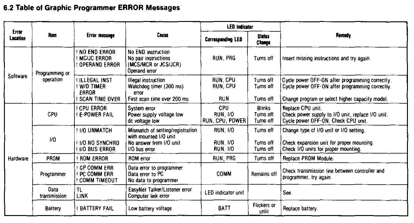
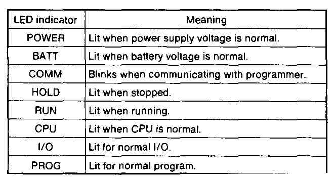
FIG. 7 Page from installation manual of Cutler—Hammer D500 PCL indicating
errors. (Courtesy Eaton Corporation, Cutler—Hammer Products)
6.0 Troubleshooting
The prime diagnostic device is the LED’s on the CPU and n each module. Regular observance of these LED’s will alert the user to potential or actual trouble. Other diagnostic information is available through peripheral devices like the programmer.
6.1 Table of Graphic Programmer ALARM Messages
Alarms are displayed in the message area of the graphic programmer display panel. Following are the alarms which may appear.
BATT — Battery condition or low voltage alarm.
IL — EasyNet error.
LINK .— Abnormal occurrence in Computer Link.
DIAG — An error has occurred during diagnosis.
DOWN — The processor is in the ERROR DOWN state, an Error Reset command is required to HALT the system.
6.2 Table of Graphic Programmer ERROR Messages
6.3 Interpreting LED Displays
All eight LED indicators on the basic unit are lit or blink during normal operation. Should one or more LEDs not light, a malfunction is indicated.
== ==
Methods of Control
Open-loop control is the simplest form of control used. It uses no feedback, as in a closed-loop system. The feedback system can provide many kinds of control action and correction. Proportional control is the simplestform, but it is rarely sufficient by itself. In addition, derivative and integral calculations are also used. This type of feedback and control is based on the rate of change of the error (the derivative) plus the integral of the sum of the errors, as well as the size (proportional) of the error. This combination of error correction used in control systems, called PID, is one of the most widely used forms today. FIG. 9 shows a general flow diagram using feedback.
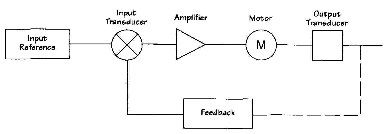
FIG. 9 Block diagram of general flow with feedback.
Relationship of Digital Logic to Relay Logic
Most larger programmable controllers do not require digital gate logic principles. They are programmed by keying in lines, connections, contacts, coils, timers, or functions. However, many smaller programmable controllers have keyboards with LED displays and digital logic symbols on the keypad, such as AND, OR, and NOT, and a dot, +, —, 0, or =. These are Boolean algebra operators used with logic terms.
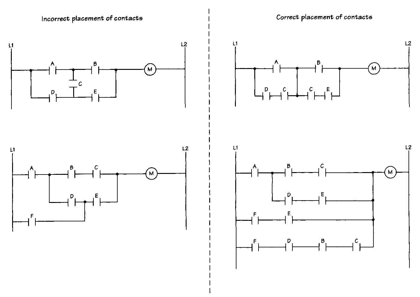
FIG. 8 Incorrect logic and the equivalent correct logic. Correct placement
of contacts; Incorrect placement of contacts.
The voltages used to operate programmable controllers are in the 5- to 15-V DC range, but the process signals are generally much greater. The input/output modules provide the interface between the controller and the actuators and transducers. For NEMA size 4 or larger motor starters, a standard control relay is required to connect the output module. When used this way, the relay is called an interposing relay.
Converting from Relay or Logic Diagrams
The following examples demonstrate how gate logic can be translated to relay logic and then implemented by a programmable controller.
A conveyor system is to be controlled by several inputs. It is not important at this time how those inputs are detected, because we are interested only in the logic and control portion of this circuit at present. The inputs in this example are simple momentary-contact push but tons. The conveyor will run if any one of three switches is activated, and it will stop if any one of three other switches is activated. FIG. 10 demonstrates the gate logic to implement this problem. This same circuit can be implemented by the relay logic shown in FIG. 11. The relay ladder diagram would be converted to a programmable controller, as shown in FIG. 12. This circuit requires any one of the start buttons to continue to be depressed for the conveyor to continue running. As soon as the start button is released, the conveyor will stop. The use of momentary-contact push buttons for this application is not too realistic for this type of circuit. To allow the conveyor to continue to run after any of the three start switches is pressed, a sealing contact from the motor can be added to the circuit. This contact is shown in FIG. 13.
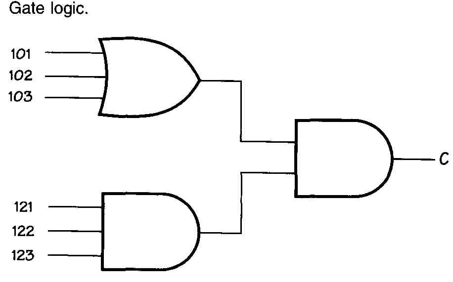
FIG. 10 Gate logic.
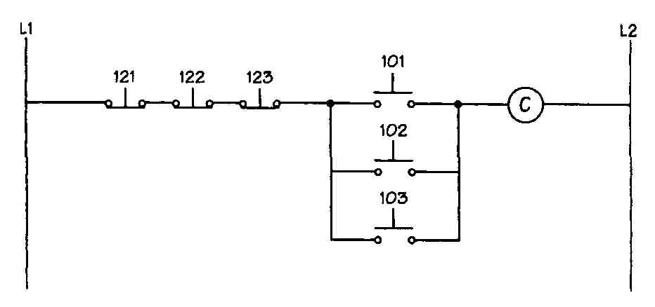
FIG. 11 Relay logic.
The actual wiring for relay logic circuits may be come rather complex, although the programmable controller wiring remains fairly simple. For example, the reversing motor control circuit shown in FIG. 14 is fairly standard. The dotted lines connecting the REV and FWD push buttons indicate that these are interlocked; when one is closed, the other must be open. For the programmable controller, all the interlock and sealing contacts are a part of the program portion, and the only wiring required includes the start and stop buttons for forward and reverse, the motor connections for forward and reverse, and the red and green indicator lights. This wiring diagram is shown in FIG. 15. The programmable controller logic would be similar to that shown in FIG. 16.
Sequential Logic Control
When various devices such as pumps, motors, or timers need to be activated in a particular order and one step must be completed before the next, the system is referred to as a sequential system.
In the beginning, these systems were designed mostly by intuition, experience, and trial and error. Such a design was very impractical for large and complex systems, so a more systematic method of design became necessary. Flow tables, merged flow tables, and Karnaugh maps are used to design what is referred to as an asynchronous system. However, this system can become very impractical for even medium-sized circuits. Also, if only one small change is made, a whole new solution must be derived. One solution to this problem is to use commercially available sequential-system programmers. Such programmers involve either punched-card or punched-tape readers. These systems are extremely flexible but rather expensive. Programmable sequence controllers can provide the greatest flexibility and convenience. Also called logic counter programmers, they can be assembled from completely compatible with existing logic elements. Logic counter programmers keep track of program steps by counting them.
The use of programmable logic controllers allows the individual required program steps to be stored in memory, rather than using individual switching elements for the steps. The programming steps for sequential logic are very similar to those of combinational logic from earlier discussions:
1. Describe the process.
2. Create a flowchart or function diagram.
3. Identify conditions and convert to Boolean equations.
4. Translate the Boolean equations into ladder logic.
Relay ladder diagrams or logic circuits are not normally used to represent sequential logic circuits, since the diagrammatic layout would become far too complex and difficult to follow. Flowcharts can also become un wieldy. Consequently, function charts or diagrams tend to be used most often. A function diagram is shown in FIG. 17. Note that the function diagram is laid out much like a flowchart.
Limitations of Ladder Programming
Ladder programs are ideal for combinational and simple sequential tasks. Full documentation is required for small programmers, since they have no means of adding comments to the circuit. Ladder diagrams are much too cumbersome to be used with most complex sequential tasks. They are difficult to design as well as troubleshoot.
APPLICATIONS OF PROGRAMMABLE CONTROLLERS
Programmable controllers are often used in robotics as either the controllers for individual robots or as overall standard, commercially available logic elements that are
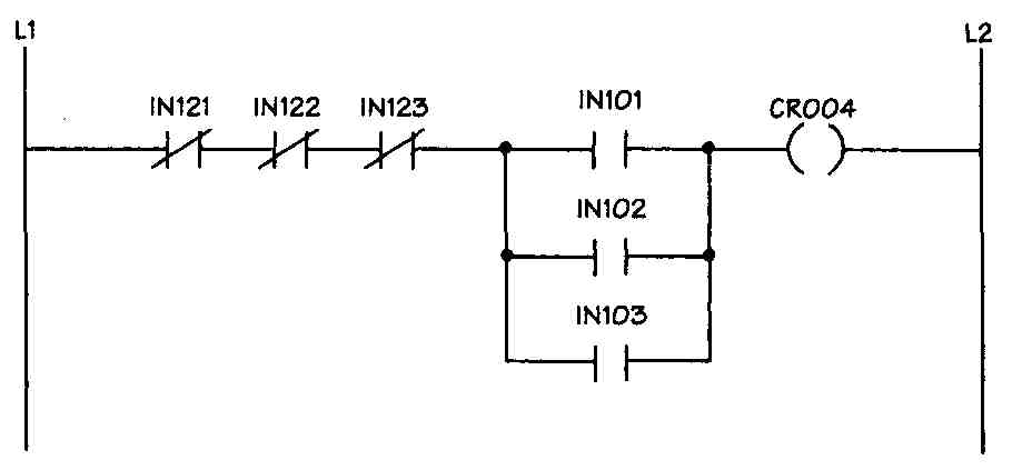
FIG. 12 Programmable controller logic.
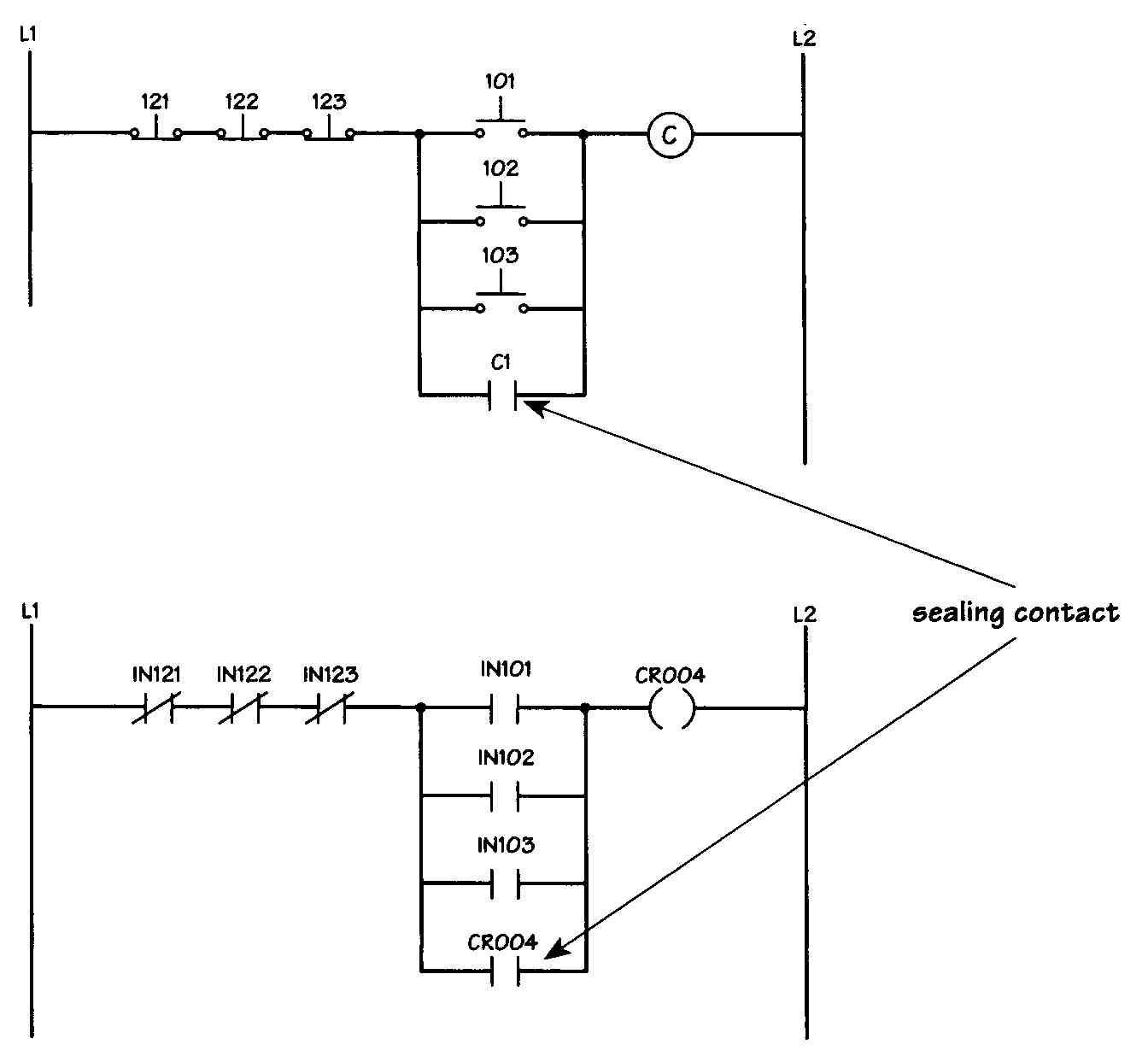
FIG. 13 Addition of a sealing contact.
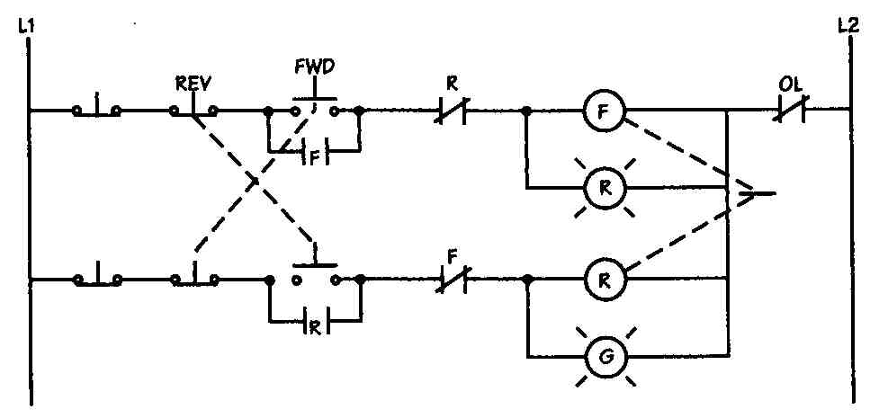
FIG. 14 Reversing motor relay logic control.
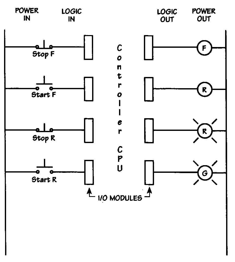
FIG. 15 Wiring of a programmable controller.
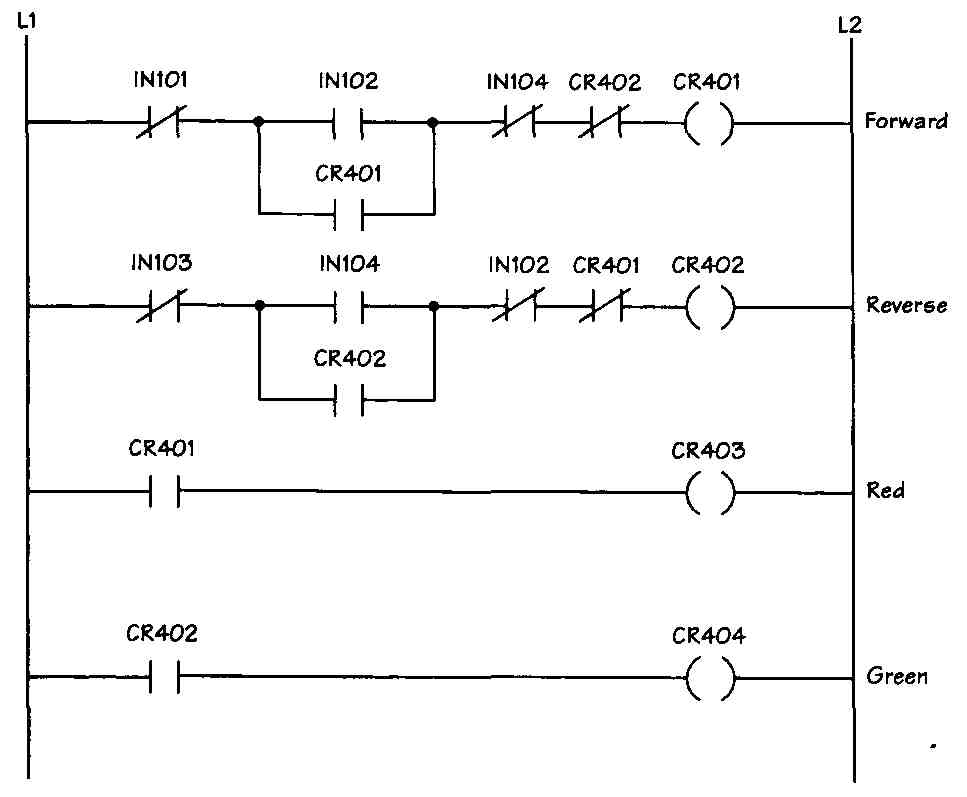
FIG. 16 Programmable controller logic.
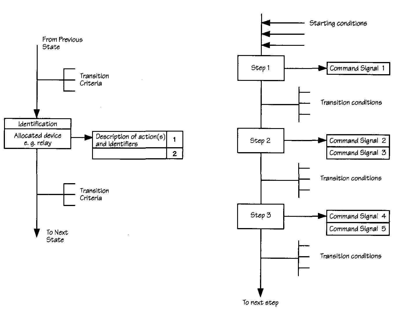
FIG. 17 Function diagram.
Limitations of Ladder Programming
Ladder programs are ideal for combinational and simple sequential tasks. Full documentation is required for small programmers, since they have no means of adding comments to the circuit. Ladder diagrams are much too cumbersome to be used with most complex sequential tasks. They are difficult to design as well as troubleshoot.
APPLICATIONS OF PROGRAMMABLE CONTROLLERS
Programmable controllers are often used in robotics as either the controllers for individual robots or as overall system controllers for a number of robots. More often, a microcomputer is used to control a robot to provide the necessary and adequate processing speed. Programmable controllers are used to process large numbers of input and output signals when only simple logic functions are required on the inputs. Programmable controllers are a very reasonable and cost-effective choice for point-to-point and limited-sequence robots.
The next step is to link and group programmable machines into flexible manufacturing cells, which might include robots, CNC machines, a conveyor system, and a programmable controller.
Robots
The definition of a robot as adopted by the Robotic Industries Association is as follows:
A robot is a reprogrammable multifunctional manipulator designed to move material, parts, tools, and specialized devices through variable programmed motions for the performance of a variety of tasks.
Industrial robots can be categorized by a number of different features. For example, they can be servo and non-servo-controlled or they can have different degrees of freedom. A degree of freedom is an axis of motion for the robot. Robots with six or more degrees of freedom are classified as medium or high technology. As more degrees of freedom are added, complexity and cost can quickly become prohibitive in many applications. Most industrial tasks require from three to six degrees of freedom, or axes of motion. Keep in mind that limited axes of motion do not mean inaccurate or limited usefulness. In robots, more is not necessarily better. A robot should be selected to perform only the needed tasks; extra capabilities can simply result in additional and unnecessary costs.
A two-axis robot can have both linear and rotary movement. Basic robot elements include some sort of mechanical arm and either computer control for the most flexibility or a fixed-sequence controller. The three basic components of a robot include the controller, the manipulator, and the end effector, or gripper. FIG. 18 identifies the six possible axes of rotation in a complex robot. The controller ( FIG. 19) includes both the hardware and software needed to control the movements of the robot. The manipulator is the base and the arm itself. It is usually internally powered. Each individual joint in a robot arm can have up to three axes of movement, and each axis has its own actuator. These actuators are either mechanical, electrical, or pneumatic. Each of these presents its own advantages and disadvantages. The gripper, or the robot hand, is used for grasping, moving, spray painting, welding. and other similar tasks. The hand can have fingers that are mechanical, magnetic, or vacuum devices or can just be some type of tool.
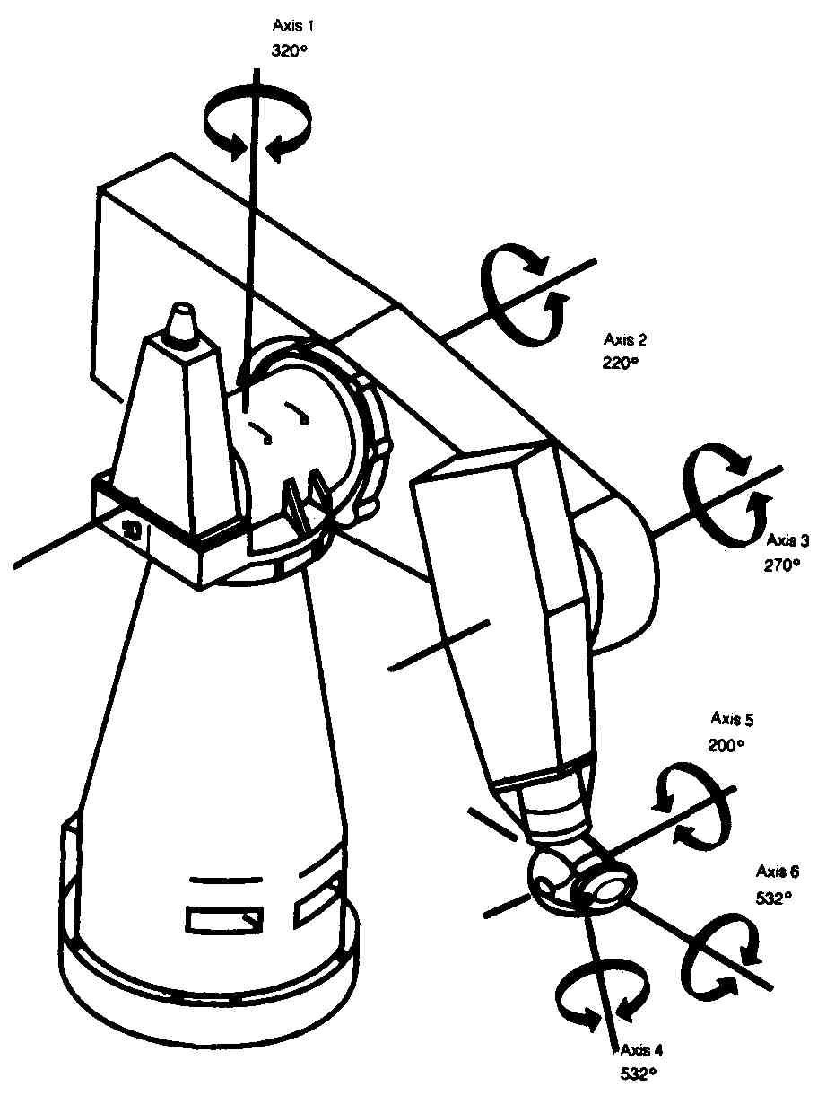
FIG. 18 Robot with six axes of movement.
The simplest of robots are typically two-position (sometimes called bang-bang) robots, the positions being up and down or in and out; these robots perform very limited tasks. Programmable controllers can often be used to control these low-technology robots. The programs for these robots usually contain only time delays or sequential events. Very sophisticated robots can perform many tasks and have very flexible movements. A robot such as Cincinnati Milacron’s T3 is one of these remarkable units. It allows for six degrees of freedom and is used in many industrial applications.
There are four primary classifications of the functions performed by robots:
1. Pick and place
2. Point to point
3. Continuous path
4. Assembly (which combines continuous path with machine tools such as drills or lathes)
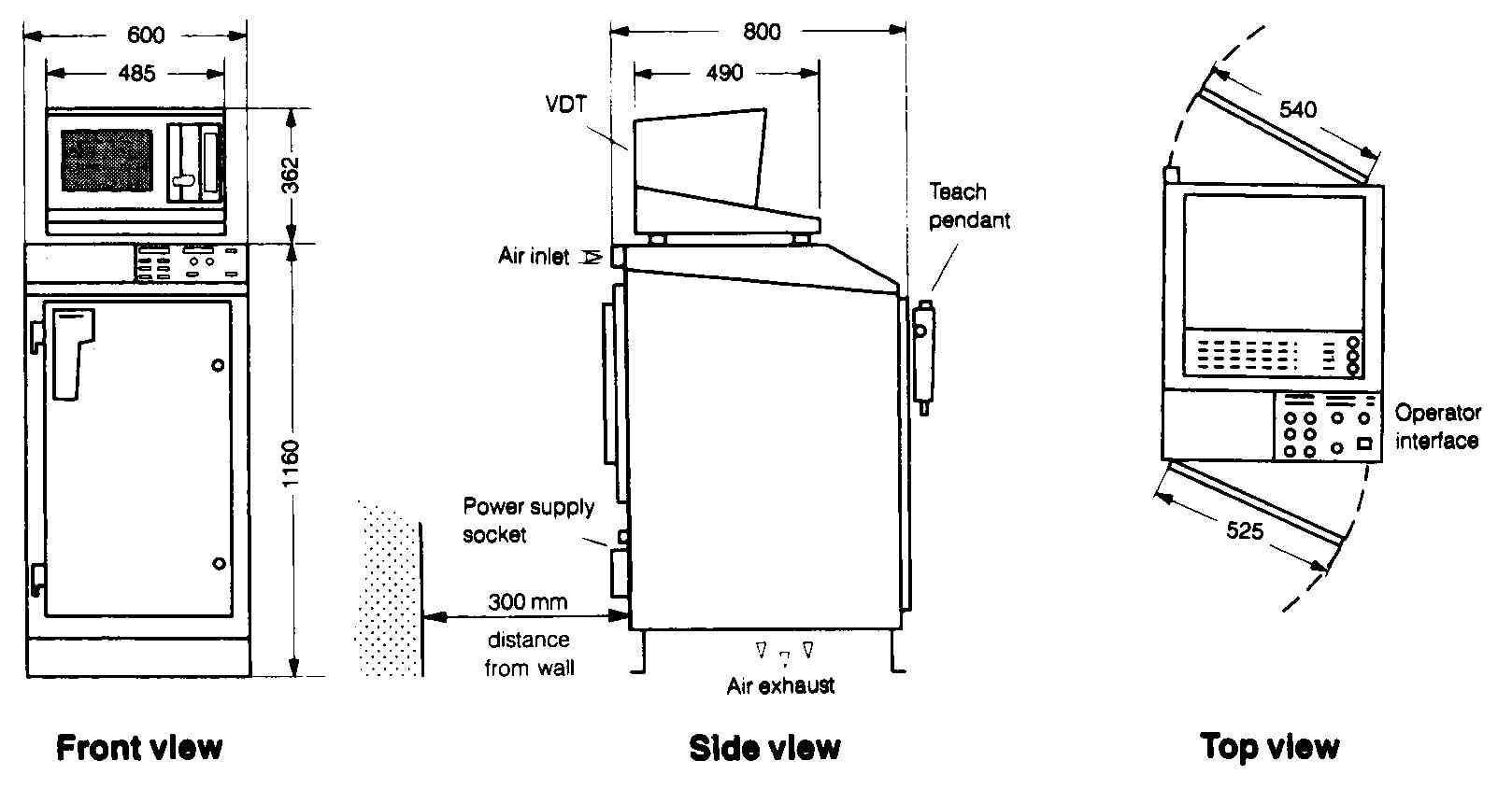
FIG. 19 Controller for PUMA 761/762 robot. Teach pendant; Operator
interface
The more flexible the robot, the more complex the control system has to be. A control system is used to cause a process to occur and may be able to adjust for disturbances that will affect the final product of this process. A block diagram of a general control system with feed back is shown in FIG. 9. The feedback may be a signal from a meter reading, a limit switch, a pressure gage, or any other device used to measure a disturbance.
Each different robot has a different operating envelope or space needed for clearance of the arm movement based on the dimensions of the arm, gripper, base, and so on, as well as the directions of movement. FIG. 20 shows various types of operating areas or envelopes required. A robot with a simple linear in-and- out arm movement does not require any side-to-side clearance or up-and-down clearance.
The programming of a robot includes designing the work pattern that must be performed so that the robot can operate without human intervention. When a person programs a robot to perform a task, that person must generally be skilled in performing that task. There are several methods of programming a robot, and the method used has a good deal to do with the complexity of the robot as well as the task to be performed. Many robots have an attached pendant or training box that allows the operator to move the arm through a series of steps and points. This situation requires the operator to move each axis for the robot until it is in exactly the right place. The movements are not done in real time, so the operator should make certain that the series of points or movements, when connected, do not require the arm to travel through the base of the robot or to make too large a movement at once. If the arm needs to move over a large distance, it is better to create a series of small moves so that the final movement is not too rapid or too large an individual swing. Most robots have built-in self-preservation. If you do attempt to move the arm from one point to another in a straight line that would cause the arm to crash into the base, the robot will not perform that task. Some robots are “trained” by actually grasping handles and moving the robot arm through the task to be performed. This is sometimes called teach by showing or walkthrough. It can also be called continuous path, since you are moving the robot on a continuous path rather than from individual point to individual point. This method requires a great deal of memory and can be a problem when the manipulator arm is quite heavy. As the arm is moved through a sequence of steps, a sample of the arm’s position is made and entered into the control program. Off- line programming can also be used to control the robot’s movement. This is sometimes referred to as the con trolled-path method, and it takes advantage of the computational ability of the computer interface. One way of producing the controlled path is for the operator simply to move the arm with the pendant; the computer can then generate the path to produce that movement.
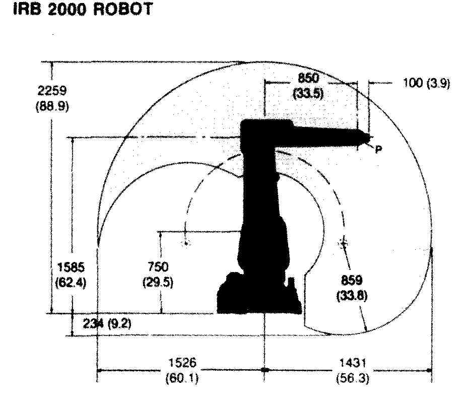
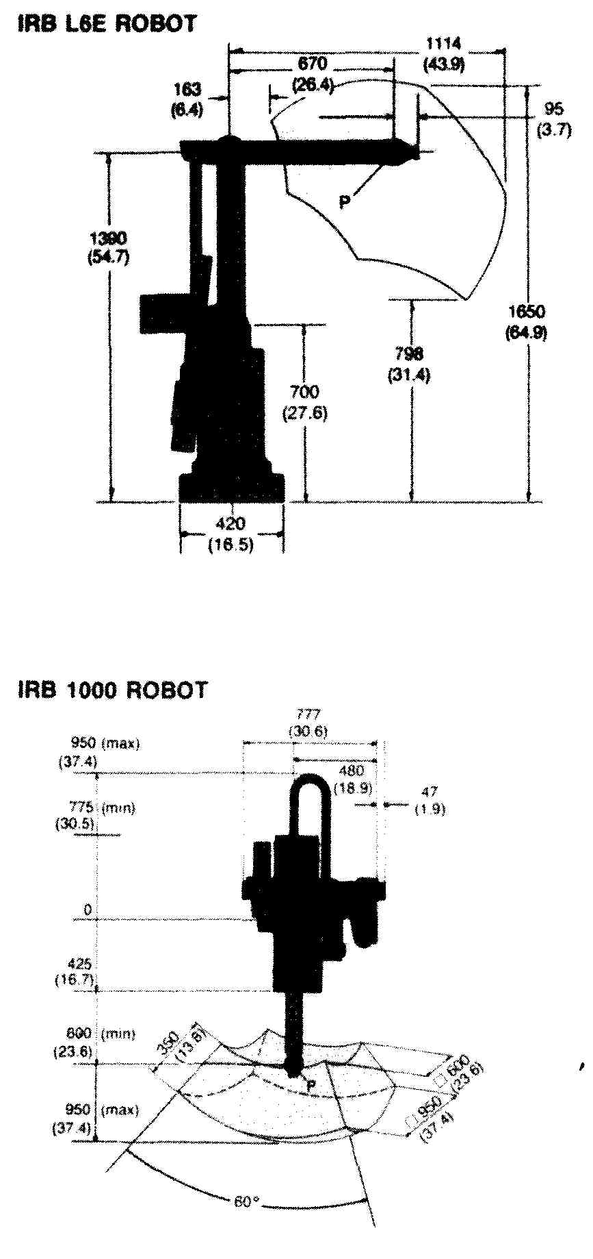
FIG. 20 Working range, or operating envelopes, of various robots. (Courtesy
ABB Robotics, Inc.)
Software for controlling robots is as diverse as popular programming languages for general-purpose computers. Some of the more popular languages available are VAL (Westinghouse), AML (IBM robotics), RAIL (Automatix), and T3 (Cincinnati Milacron). Also, BA-SIC and PASCAL can be used for real-time robot control. The basic function of each of these languages is to move the robot arm through a series of tasks. Robots can be found performing in the following work environments:
1. Spray painting
2. Parts transfer and assembly
3. Electronic and PCB assembly
4. Plastic molding
5. Machining, welding. and finishing
6. Loading and unloading machines or machine tools
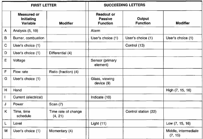
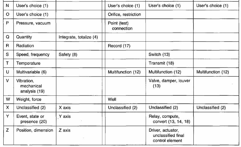
TABLE 1 Identification Letters
INSTRUMENTATION
Very few control systems exist without instrumentation used as either instrumentation-monitoring or instrumentation-actuated controls. The link between instrumentation and control circuits becomes more obvious when one considers using automatic control in response to measurements. For example, a process that needs water cooling could actuate water flow after a tempera ture indicator signals a high temperature. Instruments are required to measure many different variables. From an electrical point of view, there are only two broad classes of instruments: analog and digital. Analog instruments generally require a power supply and often re quire some wiring to obtain the necessary signals for operation. Often, digital instruments used to measure flow, pressure, or temperature are included in discussions of instrumentation, because they perform the task of measurement. But they should be included in discussions of control circuits, because one of their primary functions is that of control. The need for instrumentation introduces a unique set of drawings for industrial control. These drawings are called balloon drawings, and they are found only in instrumentation diagrams.
There have been two sets of standards for symbols used in the area of instrumentation. The most widely used in electrical areas is ANSIIISA-S5.1-1984, Instrumentation Symbols and Identification, from the Instrumentation Society of America, which was approved on November 5, 1986. The other set is from Scientific Apparatus Makers Association (SAMA). These standards use a method of functional diagramming to describe functions with blocks and designators. In addition to these standards, the key elements of ISA-S5.3, Graphics Symbols for Distributed Control/Shared Display Instrumentation, Logic, and Computer Systems, were incorporated into ISA-S5.i with the intent of with drawing that document after the approval of the revision of ISA-S5.1. The standards cover instrumentation used in many areas, such as chemical, petroleum, power generation, air conditioning, and metal refining processes, to name a few. The emphasis here is on power generation.
Looking up the definition of balloon in the standard gives the following:
Balloon Synonym for bubble.
Bubble The circular symbol used to denote and identify the purpose of an instrument or function. It may contain a tag number. Synonym for balloon.
The tag numbers or other identification include information such as plant area designation or the function of the instrument itself. Each set of tag numbers and identification can be translated using designations from the standard, as shown in Table 16.1. The numbers in this table refer to notes in the standard. The standard should be consulted when preparing instrumentation diagrams.
The location of a particular letter in the tag string is important. The first letter is the identifier, and all other letters are for additional readouts or functions. For example, the use of the letter V as the measured or initiating variable means vibration or mechanical analysis. But using V as a succeeding letter indicates a valve, damper, or louver. The first letter, then, is determined by the measured value or a functional identification. The succeeding letters indicate additional readouts, recordings, or output functions of the instrument. In addition, special modifier letters may be used to modify the initial variable or output variables. For example, the use of T indicates temperature, but the use of TD indicates temperature differential, or the difference in tempera ture. These are two entirely different variables. FIG. 21 shows two samples of the use of this identification method. FIG. 21 (A) pictures an indicating voltmeter connected to a turbine-generator pair. The line cut ting across the circle shows that the primary location of this instrument is normally accessible to the operator.
The tag in FIG. 21 (B) includes the use of a modifier.
This instrument measures the temperature and engages a switch when that temperature is low. This action causes one output to split, sounding a low-temperature alarm and tripping the circuit.
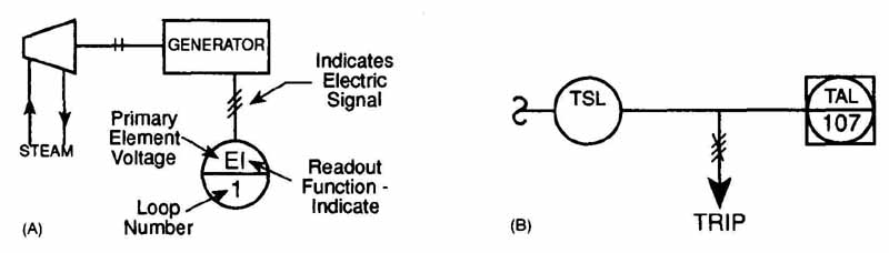
FIG. 21 Examples of primary element bubbles.
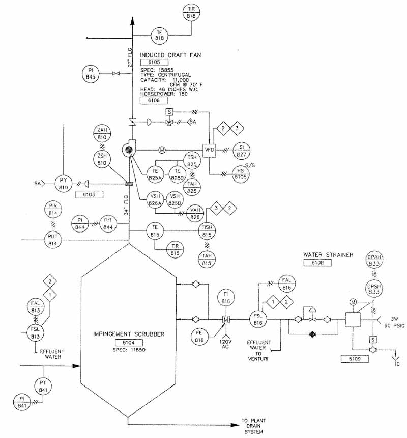
FIG. 22 Instrumentation diagram. (Courtesy Brown and Caldwell Consultants)
The numbering of the loop that contains the instruments may be done with either a parallel numbering system or a serial one. The use of a parallel numbering system requires the same starting numerical sequence for each different function or first letter, such as FT 100, TE-100, and TIC-100. For serial numbering, a single numerical sequence is used regardless of the function or first letter, such as, FT-100, TE-101, and TIC-102. The most important thing to remember is that the numbering system used should be as simple as possible.
Actual drafting practices for the use of tagging bubbles are covered in the standard. In general, good drafting practices should be followed for neatness and legibility. Adequate space must be left between symbols for notes and other information. Symbols may be drawn with any orientation, but the tag numbers should always be horizontal. Electrical, pneumatic, and power supplies are not shown unless they are required for a complete understanding of the operation. The arrangement of the diagram will reflect the functional flow and not necessarily indicate correct interconnections. These interconnections are shown on another diagram. The sizes of the tagging bubbles will vary, depending on final reductions of the finished drawing and sizes of other symbols used to represent equipment on the diagram. A suggested starting size for circles and squares to be used on large diagrams is 7/16 in. The most important consideration is consistency throughout the entire drawing. The degree of detail used in the final drawings will vary for each instance. A simple functional representation indicating what instruments are used or what variables are measured is shown in FIG. 22. This diagram indicates the kind of hardware and types of signals that will be measured.
REVIEW QUESTIONS
1 What three things must be considered for a complete control system?
2 What type of functions are performed by programmable logic controllers?
3 True or false: To program or maintain a programmable logic controller, one must be a computer expert.
4 Both the programmable logic controller and the personal microcomputer contain a microprocessor. What makes them different?
5 What is a transducer, and what is its primary purpose?
6 List the primary parts of a programmable logic controller, and discuss the function of each part.
7 Discuss the limitations found in most programmable logic controllers.
8 Why is the sequence of operations a more important consideration in programmable logic controllers than for hard-wired relay logic?
9 What is the difference between an open-loop and a closed-loop control system?
10 Why is wiring for an actual relay logic circuit so much more complex than for programmable logic controllers?
11 List some common applications of programmable logic controllers.
12 What are the three basic components of a robot?
13 List two methods of classifying industrial robots.
14 What is a degree of freedom?
15 What is an operating envelope?
16 List and describe different methods of programming, or training, robot movements.
17 Why is instrumentation an important part of a control system?
PROBLEMS
1. A motor is to be started and stopped from any of three locations. Each location has a start and stop button. Draw a logic circuit representing this. Convert the circuit drawing to a ladder diagram using relay logic.
2. A grinding machine (G) must have lubricating oil (0) whenever it is running.
Both the grinder and the oil reservoir use three-wire control, and 0 must be running before G is started. Also, if 0 stops. G must stop immediately. Draw the logic circuit representing this and convert it to a ladder diagram using relay logic.
6. On a size B sheet, draw the programmable controller circuit shown here.
PROBLEM 6 Programmable controller circuit. (Courtesy of Eaton Corporation,
Cutler—Hammer Products)
7. Shown is the chassis for the D100 programmable logic controller. On a size B sheet, draw these views at one-half scale, showing all dimensions.
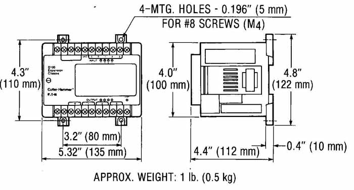
PROBLEM 7 D100 programmable controller chassis. (Courtesy of Eaton
Corporation, Cutler—Hammer Products)
8. Shown is a chassis for a programmable controller. On a size B sheet, draw these views at one-half scale, showing all dimensions.
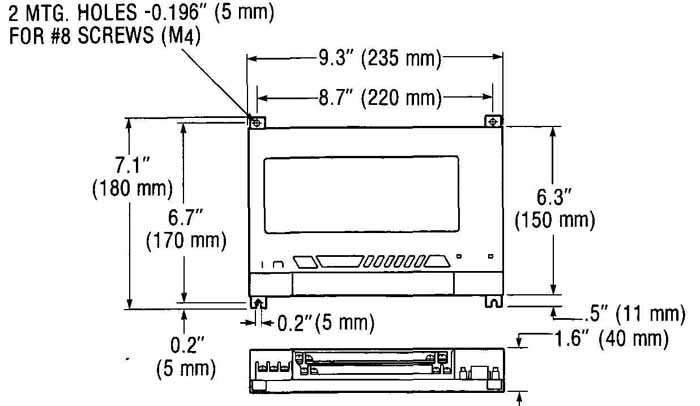
PROBLEM 8 Programmable controller chassis. (Courtesy of Eaton Corporation,
Cutler—Hammer Products)
9. On a size C sheet, draw the PLC enclosure shown.
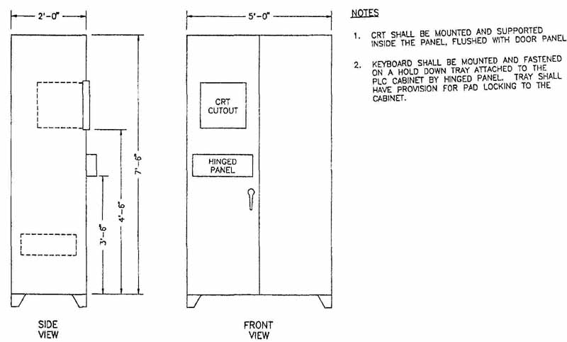
PROBLEM 9 PLC enclosure. (Courtesy of Brown and Caldwell Consultants)
10. On a size B sheet, draw the operating envelopes shown for the IRB 3200 robot. Use metric dimensions.
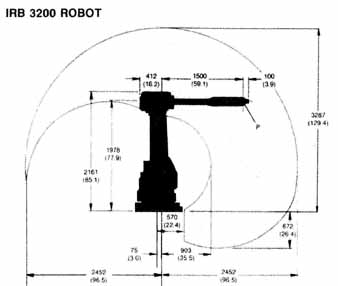
PROBLEM 10 Robot operating envelope. (Courtesy of ABB Robotics, Inc.)
11. On a size B sheet, draw the operating envelopes shown for the IRB 3000 robot. Use metric dimensions.
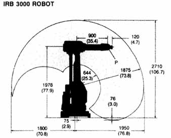
PROBLEM 11 Robot operating envelope. (Courtesy of ABB Robotics, Inc.)
12. On a size C sheet, draw the wiring diagram for the programmable controller shown.
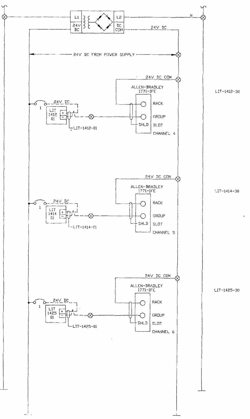
PROBLEM 12
13. On a size C, sheet draw the Packer I/O detail shown.
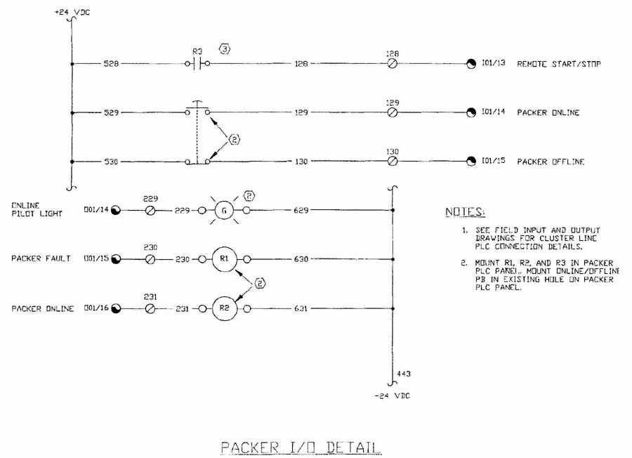
PROBLEM 13
14 On a size B sheet, draw the instrumentation circuit shown in FIG. 14.
15. On a size C sheet, draw the ladder diagram shown.
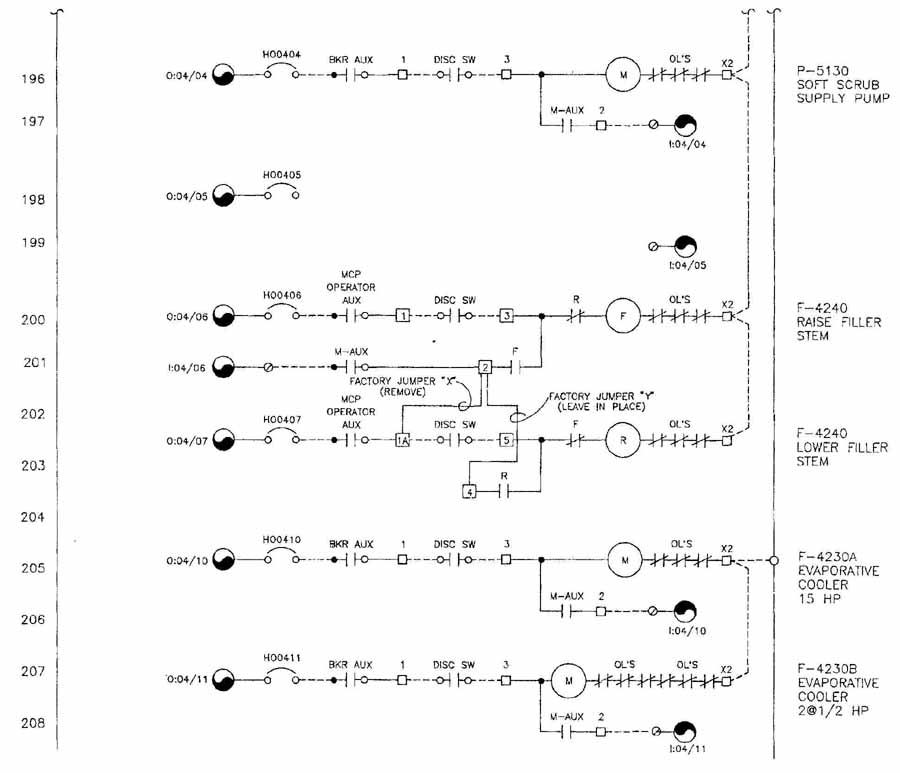
PROBLEM 15
16. (Advanced Problem) On a size C sheet, draw the schematic diagram shown.
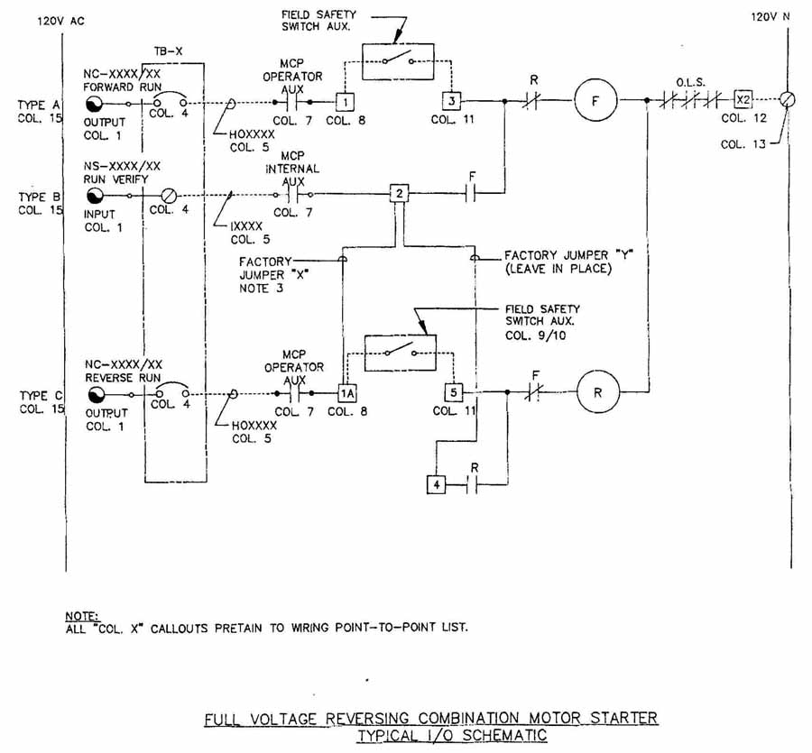
PROBLEM 16
17. (Advanced Problem) On a size D sheet, draw the instrumentation diagram shown in FIG. 22.