AMAZON multi-meters discounts AMAZON oscilloscope discounts
INTRODUCTION
The total packaging of an electronic or electrical item includes both the exterior form and the interior parts for securing electronic modules and other parts to the frame and enclosure. Therefore, the field of electronic packaging covers the functional and esthetic design of commercial computer products, as well as the mounting and structural configurations for modules and electronic subassemblies involving sheet metal parts. These areas can be referred to as exterior enclosures (shells) and interior securing configurations. This simple division, however, cannot always be applied to packages that incorporate both the exterior and interior package into one unit.
Exterior packaging includes the cabinet and envelope design for all types of electrical, electronic, and computer equipment. The computer products shown in FIG. 1 provide examples of the possible variations in packaging size and configuration.
Interior packaging includes the mounting plates, panels, brackets, chassis, cage, and other parts, and sub units that secure or enclose the actual electronic and electrical modules, assemblies, and subassemblies to the outer holding envelope or cabinet.
For small intrinsic units such as portable metering equipment, shown in FIG. 2, the exterior and interior division does not apply since the electronic components, circuit boards, and other parts may be at least partially secured directly to the outer shell or envelope.
Packaging can also be divided into functional categories; consumer product, private business or medical, industrial, public communications, power generation, military or space, and computer. Each category has its own design specifications based on environmental, functional, esthetic, and cost factors.
Products manufactured for sale in the consumer market include radio, stereo, video, television, calculator, personal computer, computer game, household, and transportation products. In the manufacture of military products and power generation or communications equipment, reliability and life length are the most important considerations. Private consumer products have the added requirements of a high degree of esthetic and cost engineering considerations.
Private sector business and medical applications include computers, communication equipment, and medical or dental equipment. Medical and dental equipment must be designed and manufactured according to strict government standards because of their life sustaining or threatening aspects. Medical equipment includes nu clear devices and life monitoring equipment.
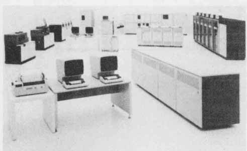
FIG. 1 Computer input, processing, and storage equipment. (Courtesy
of International Business Machines Corporation)
Industrial equipment includes electronic controls and monitoring equipment for robotics and computer aided manufacturing equipment, along with traditional industrial machinery and production or assembly equipment. The artificial vision system shown in FIG. 3 is a programmable image sensing and processing system that inspects, identifies, counts, sorts, and positions parts. It can also be used as a stand-alone sensor for robots. Robotics equipment, CAD/CAM, and other automated electronic equipment are the fastest growing and most dynamic areas of electronic engineering and package design.
Power generation and communications equipment are also extremely important areas where electronic and electrical equipment are used extensively.
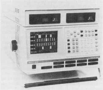
FIG. 2 Logic analyzer. (Courtesy Gould, Inc.)
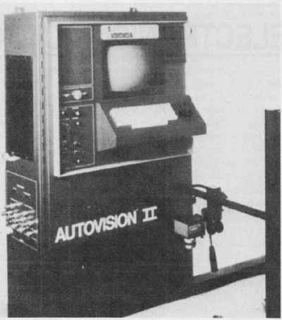
FIG. 3 Artificial vision system and control station for an industrial
robotic system. (Courtesy Automatix)
Military and space exploration applications for electronics include everything from simple hand-held enemy detection systems to missile and early warning systems. The military uses electronic equipment extensively on ships, aircraft, and land-based equipment. All military electronic equipment is governed by strict Mi! Specs. Military electronic packaging must meet stringent de sign specifications, including tough requirements for strength, reliability, and operation, including human element engineering. Space exploration and satellite communications equipment, shown in FIG. 4, require the highest degree of electronic state-of-the-art design and packaging because of the extreme degrees of unknown and known variables encountered while in operation. Most state-of-the-art designs and inventions (including calculators and computers) are a direct result of the space program.
Computer equipment and products span the full range of categories: personal computers for private consumer tasks; military computers for radar, satellite, and military equipment; industrial computers to run CAM. CAD, and robotics operations; and communications and business operations computers for business tasks. CAD system hardware is an example of electronics packaging in the computer industry. Note that a CAD system’s packaging must take into account human factors of workstation design and esthetic values associated with highly visible business and engineering of fire equipment.
FIG. 4 NASA training and test facility equipment for space flight networks.
(Courtesy NASA)
DESIGN OF ELECTRONIC PACKAGING
The design of electronic packaging is such a varied and complex subject that this text is only able to introduce general design factors.
Package design starts with acquiring the limiting factors involved in the particular project. The size, material, and environmental and cost restrictions must be understood at the early stages of design.
The system’s block diagram, schematic diagram, and wiring diagram should be readily available to the package designer. The block diagram provides essential information on the number of assemblies and the individual units that make up the system. The functional relationship between main components and assemblies is also defined in the block diagram.
Schematic diagrams describe in detail the functional relationship between modules, subassemblies, and components for a particular portion of the system. All component sizes, module dimensions, and mounting requirements need to be known before the actual system can be packaged. The parts list on the schematic de scribes each component type, size, and value designation.
The wiring diagram should be available when the packaging design starts. Wiring diagrams provide information regarding the interconnection of individual units, assemblies, and main components, along with the required connections to panel switches, lights, metering components. and other parts. The physical space requirements must take into account space taken up by wires, harnesses, cables, and connection items. Sp . for wiring must include extra areas for the long wire lengths needed to provide the unit with slide-out capabilities.
Cost restrictions on package design are influenced by the eventual use of the item and governing standards. Reliability and strength factors take precedence over cost when military packaging is being designed. For consumer and business products, esthetic and human engineering factors are as important as reliability. The computer terminal and microsystem emulator shown in FIG. 5 must meet high standards for appearance and human use to be attractive and salable. The printed circuit modules on the left are packaged in the emulator shown in the right of the photograph. Size, shape, ease of maintenance, and esthetic considerations were taken into account during the package design of this product.
Environmental conditions encountered during the use of the equipment must be considered in the early stages of the package design. Temperature variation, vibration, humidity, pressure, corrosion, and other variables are important in the selection of materials, finishes. fasteners, and the general design configuration of the package. The portability of the logic analyzer shown in FIG. 2 demands environmental design considerations different from those imposed on the designer when stationary equipment is involved.
Sophisticated CAD electronic packaging programs enable the designer to pack more electronics into less space. Designers can test and refine many component arrangements, materials, and packaging configurations on-line, clearly visualizing the effect of each on the emerging design. Two- and three-dimensional programs allow the designer unlimited freedom in creative and efficient design of even the most complex systems. The 3D option allows visualization and design in pictorial views. At any point in the design process, visual interference checks can be run on even the most difficult pack aging configurations. After the design is completed, the system automatically generates assembly drawings, NC tapes, or a flat pattern for metalworking.

FIG. 5 CRT, computer, and printed circuit boards. (Courtesy Gould,
Inc.)
Package materials range from traditional metals or metal alloys to sophisticated plastics. The printed circuit board and accompanying switches, battery. and fuse compartment of a VOM, shown in FIG. 6, use a molded plastic base unit. The computer equipment in FIG. 5 is packaged in a molded plastic enclosure, which requires no upkeep since the color and texture of the plastic meet all esthetic and functional requirements.
Metals are used where durability and toughness are more important than esthetics. The logic analyzer in FIG. 2 has a metal shell. A variety of sheet metal materials are used in package design for panels, chassis, brackets, mounts, and cabinets. Oxidizing metals must be anodized, alodined, or painted.
Exterior and Interior Parts of Electronic Packaging
Electronic packaging has been previously separated into exterior and interior packages with securing devices. Exterior configurations include all types, shapes, and sizes of cabinets, as well as simple enclosures and envelopes.
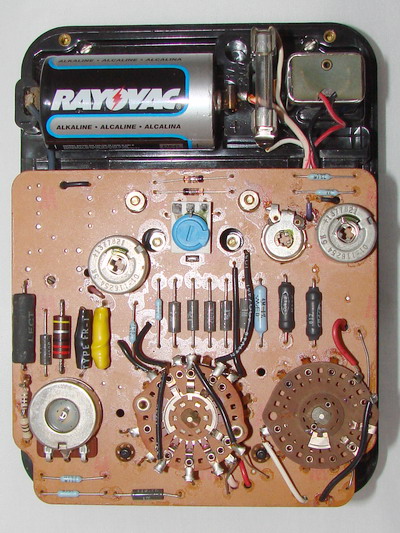
FIG. 6 Printed circuit board with the function and range switches,
the zero OHM pot, and the battery and fused compartment of the 260 VOM.
(Courtesy Simpson Electric Co.)
Cabinets range from standard units to custom-de signed units for specific users. The maze of electronic equipment shown in FIG. 4 is an example of user- defined, custom-designed packaging. Electronic equipment is mounted in a cabinet designed for easy access and use by the operator. A standard cabinet as shown in FIG. 7 is a unit designed for consumer purchase to meet the needs of a variety of users. Standard cabinets are used for computer memory expansion units and a variety of electronic equipment.
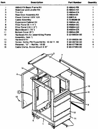
FIG. 7 Cabinet and parts list. (Courtesy Digital Equipment Corp.)
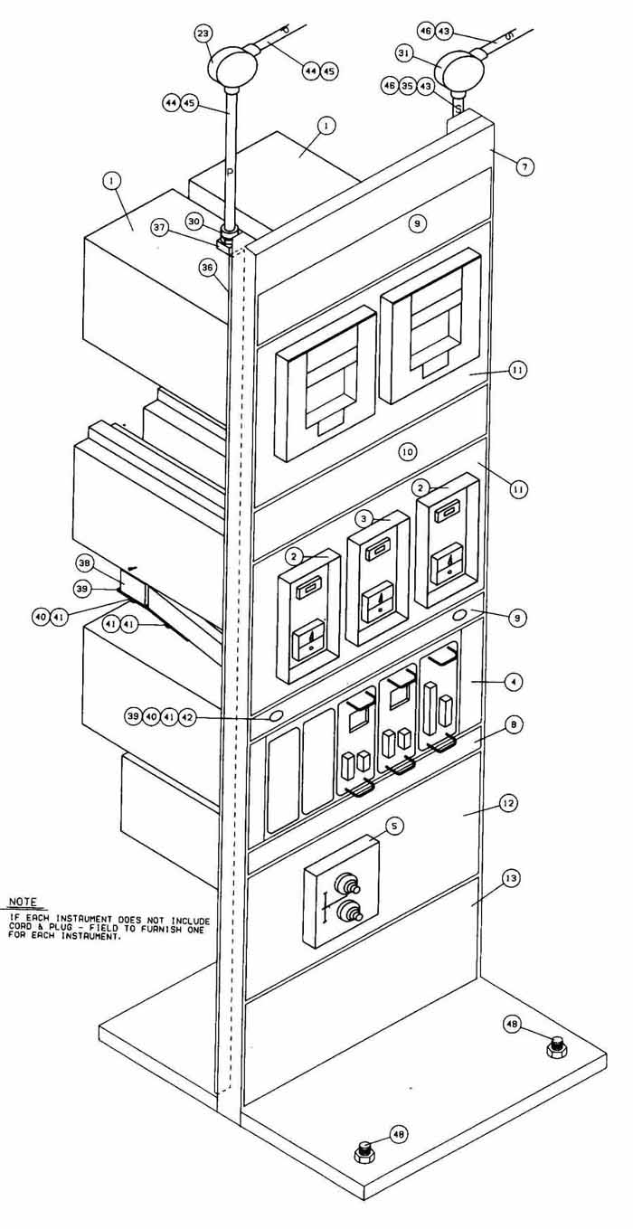
FIG. 8 Pictorial of rack and panel assembly (see Figs. 9 and 10). (Courtesy
Interactive Computer Systems, Inc.)
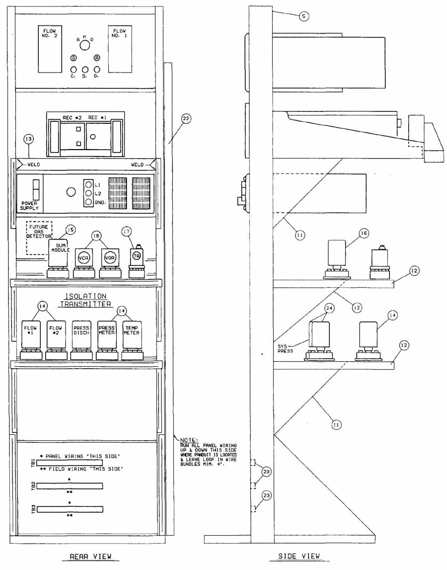
FIG. 9 Rack and panel assembly (see Figs. 8 and 10). (Courtesy Interactive
Computer Systems, Inc.)
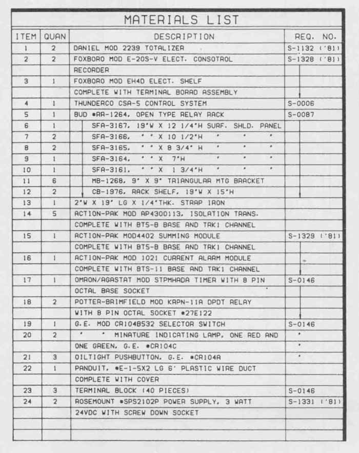
FIG. 10 Parts list for rack and panel assembly shown in Figs. 8 and
9. (Courtesy Interactive Computer Systems, Inc.)
Rack and panel assemblies are shown pictorially in FIG. 8, with the rear and side views shown in FIG. 9. They consist of separate electronic packages, units, assemblies, and modules mounted in their respective chassis or enclosures, secured to adjustable drawers or racks. Each unit is attached and wired to its respective front panel. Rear panels are not used on this type of open rack and panel assembly design. All wiring between units is confined to the wire duct. FIG. 9 (22). on this particular configuration. Inmost cases, the design and layout of electronic equipment on the rack and panel assembly must take into account space for wiring and cable connections. Each rack in this figure can be adjusted for the electronic equipment to be mounted on the structure. A detailed materials list for this rack and panel assembly is provided in FIG. 10.
Chassis
Chassis design includes modules and panels. Normally, a module is housed in some form of chassis arrangement as in FIG. 11, where the PC board module has been secured to a sheet metal chassis, which in turn is fastened to the molded plastic enclosure.
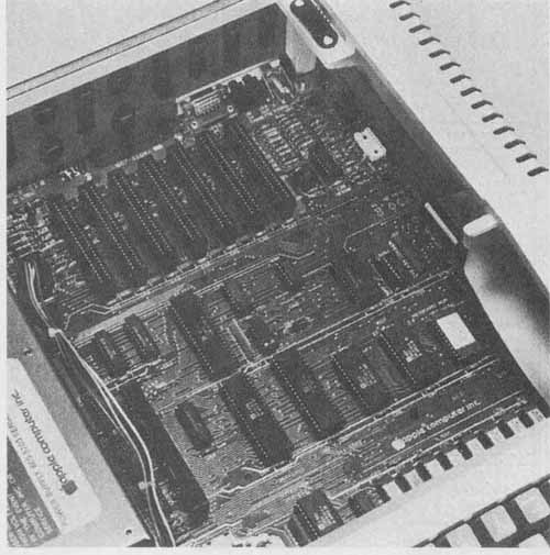
FIG. 11 Close-up view of main logic board secured to the sheet metal
chassis and molded plastic computer enclosure. (Courtesy Apple Computer,
Inc.)
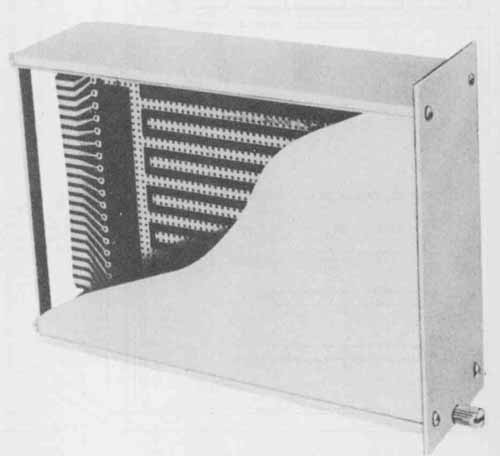
FIG. 12 Module for expansion cage. (Courtesy Vector Electronics Co.)
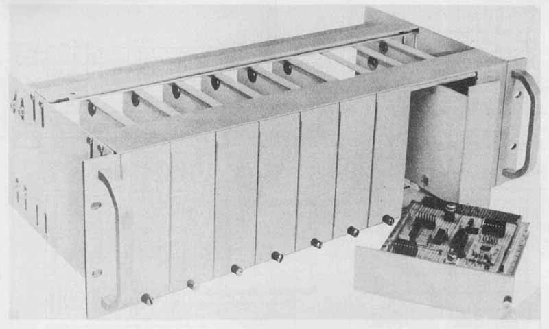
FIG. 13 Fully assembled ten-module cage. (Courtesy Vector Electronics
Co.)
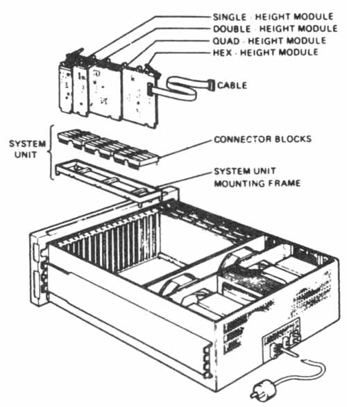
FIG. 14 Expansion mounting box with built-in power supply. (Courtesy
Digital Equipment Corp.)
Modules are specific electronic packages providing one separate function to the total electronic system. Each module can be separately removed, serviced, maintained, and replaced individually without disturbing other parts of the system. Electronic modules may be a single PC board or a subassembly made up of multiple PC boards and individual components as long as they form a complete, separate individual function. In general. the term module is used to refer to any plug-in, printed circuit board, whether completely blank as in FIG. 12, provided with IC pads and connections, or fully assembled as a working entity ( FIG. 11).
In FIG. 12 the plate, board, and panel are shown encased in a drawerlike assembly. The chassis assembly shown in FIG. 13 consists of a series of individual pull-out (drawerlike) modules installed in a cage. Each cage unit is designed to be mounted on a cabinet or rack and panel assembly.
The expansion mounting box shown in FIG. 14 has a built-in power supply, mounting frame, connector blocks, and examples of four possible module variations. This system unit is a set of module connecting blocks in a mounting frame, which in turn mounts to a cabinet or rack and panel assembly like the one shown in FIG. 8. The box is a drawer-like, rack-mountable, fully enclosed chassis for circuitry that cannot be housed within a computer’s own enclosure. This box is also known as an expansion mounting chassis.
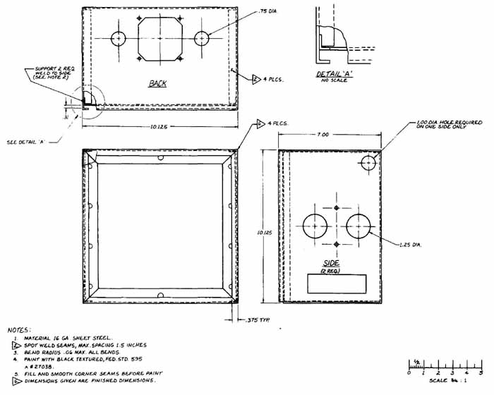
In FIG. 15, another example of an expansion enclosure (chassis) is shown along with its individual retainers for securing separate PCB modules that are positioned vertically or stacked. The front of a chassis such as this is attached to a functional panel. The chassis in FIG. 16 is a completely detailed custom enclosure. The finish, marking, and drilling requirements are specified in the notes. The chassis is a completely welded unit.
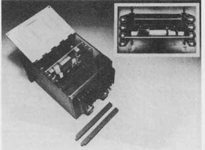
FIG. 15 Circuit-board retainer for enclosure. (Courtesy International
Electronic Research Corp.)
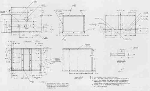
FIG. 16 Chassis detail. (Courtesy J. Higgins)
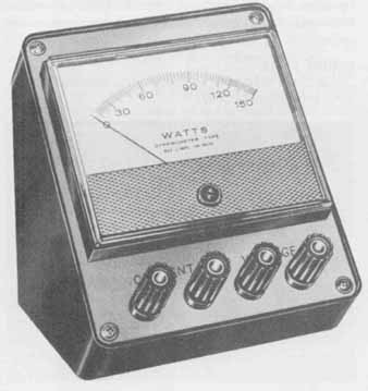
FIG. 17 Wattmeter. (Courtesy Triplett Corp.)
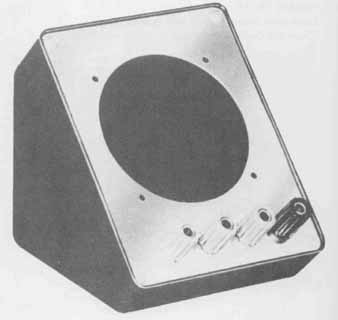
FIG. 18 Meter panel and enclosure for wattmeter shown in FIG. 17. (Courtesy
Triplett Corp.)
Panels
Panels are provided on most electronic packages. A panel serves as a mounting surface for indicators, dials, lights, switches, buttons, meters, and other controls. Panels can be as simple as the front panel of a logic analyzer ( FIG. 2) or as complex as the multiple control panels for a NASA tracking station ( FIG. 4). Panels for specific consumer or industrial products also have the brand name, logo, and other identifying cal- louts embossed, engraved, painted, labeled, or otherwise attached to their surface for easy identification. The small mounting plate (panel) in Figs. 17 and 18 shows the meter mounting cutout and securing holes and the current and voltage identifying markings.
FIG. 19 shows the suggested panel and control station layout for industrial controls. FIG. 20 shows a rear-panel assembly drawing of a data-acquisition computer.
A complete hard-drive assembly is shown in FIG. 21. FIG. 22 shows a detailed RF panel.
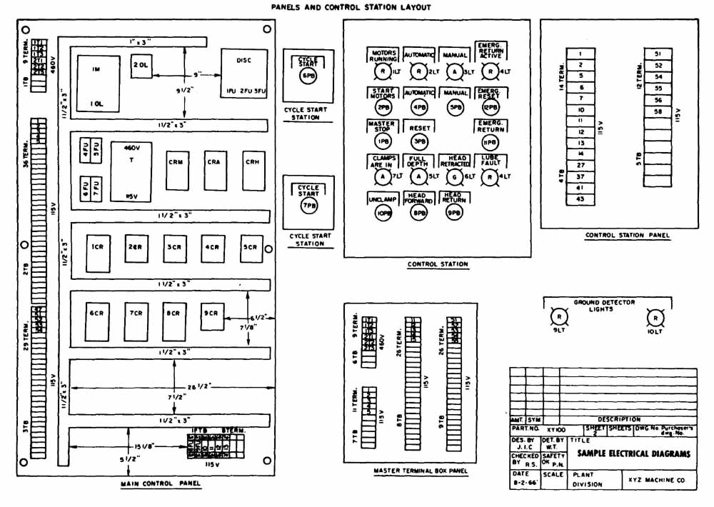
FIG. 19 Panels and control station layout. (Courtesy Joint Industrial
Council)
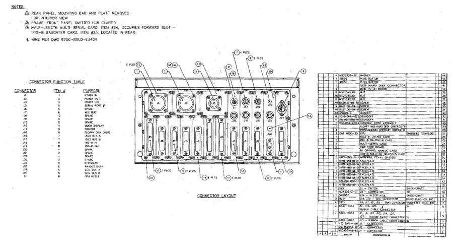
FIG. 20 Rear panel assembly for data-acquisition computer.
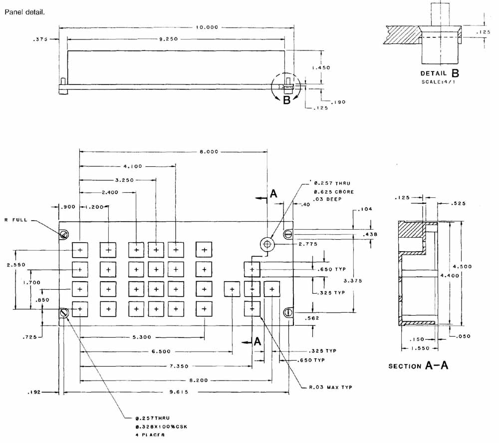
FIG. 22 Panel detail.
SHEET METAL LAYOUT
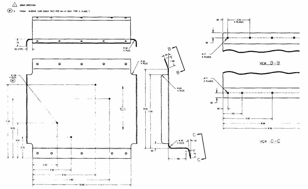
Much of electronic packaging involves the use and fabrication of sheet metal parts to be used for chassis, panels, mounting plates, and a variety of enclosures and envelopes. Sheet metal parts are normally made from a blank of sheet metal cut to the required size. Panels, mounting plates, and other parts are normally flat sheets of metal length. All surfaces of the object are connected along their common bend lines. The chassis enclosure shown in FIG. 23 has been developed as an inside-up pattern in FIG. 24. Both drawings are dimensioned. Note cut to the functional outline, with the proper slots and holes punched out or machined as required. These flat, thin pieces of metal can be a variety of thicknesses determined by the needs of the packaging design.
The maximum thickness of sheet metal parts that must be bent, formed, or shaped in some way is limited by how easily the material used can bend. Sheet metal configurations such as enclosures, chassis, cages, and some cabinets are laid out as developments of the original design. A development is the unfolding of the object onto one plane. The flat pattern development can then be machined as required, before the forming or bending process.
A variety of electronic parts and enclosures is made from flat sheet stock material. Parts designed to be produced of flat materials are cut from a pattern that is drawn as a development from the orthographic/multiview projection. The complete layout drawing of a part showing its total surface area in one view is then constructed with true length dimensions. This fiat plane drawing shows each surface of the part as true shape; therefore, all lines in a development pattern are true that the dashed lines on the pattern development are bend lines, lines along which the flat sheet metal will be bent.
A pattern is made from the original development drawing and used in the shop to scribe or set up the true shape configuration of a part to be produced. The actual flat sheet configuration is then cut according to its pattern. The final operations include bending, folding or rolling, and stretching the part to its required design. Welding, gluing, soldering, bolting, seaming, or riveting can be used to join the parts with seam edges.
The four most common shapes that can be developed are the prism, pyramid, cylinder, and cone in all of their variations. The surfaces of an object are normally unfolded or unrolled onto the plane of the paper. The actual pattern drawing of the object consists of showing each successive surface as true shape. connected along common edges. On some designs where the part is to be boxed or completely enclosed, one of the edge lines serves as a seam for joining the plane surfaces.
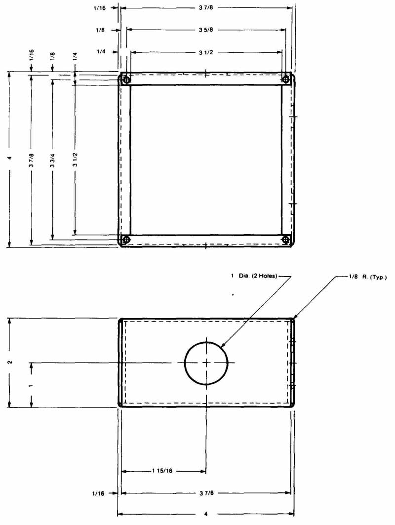
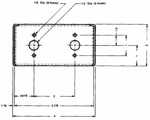
FIG. 23 Chassis enclosure detail. (Courtesy Ernie Schweinzger & Assoc.)
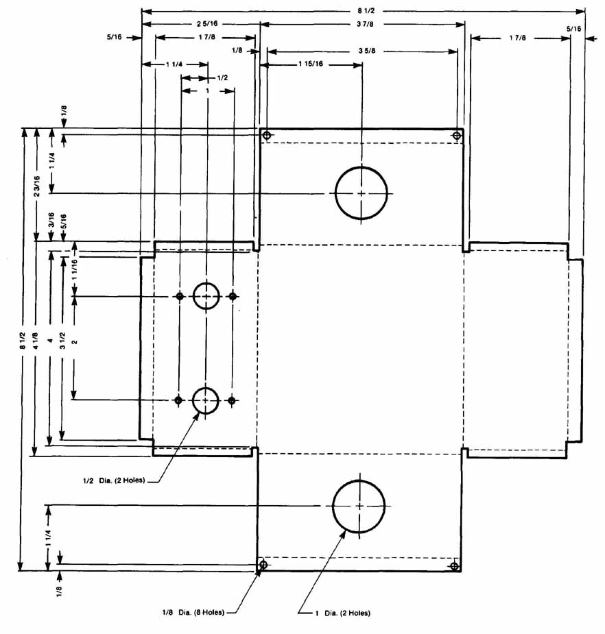
FIG. 24 Development of chassis enclosure shown in FIG. 23. (Courtesy
Ernie Schweinzger & Assoc.)
Objects can be developed as an inside-up pattern drawing; the object is unfolded or unrolled so that the inside surface is face up. In some cases a pattern may be required to show as an outside-up development. Normally, patterns are inside-up since the bending is done along the inside bend lines.
Many complex three-dimensional shapes are fabricated from flat sheet materials. The shape to be formed is subdivided into its simplest elements or planes. In electronic packaging a majority of shapes to be fabricated from sheet metal are composed of flat plane surfaces, rectangular box shapes, or two-surface brackets. These shapes are formed from a sheet of material. The sheet is first cut to the proper pattern and then folded or rolled into its three-dimensional form. Aluminum and sheet metal are common materials for this type of part.
The fabricator, working from the design engineer’s drawings and specifications, develops pattern drawings of each configuration to be produced in the fabrication shop. These patterns are made to the full size of the object and can only be made after the true lengths have been determined of all lines that lie on the pattern.
A pattern is a drawing composed entirely of true length lines. Therefore, all patterns are true shape and size, like the one in FIG. 24. Each development must be drawn accurately so that the final product has the correct shape within given tolerance limits. A bend allowance is usually provided on the pattern drawing to accommodate the space taken by the bending process. An extra tab or lap must be added to the pattern if adjoining edges are to be attached. This is called the seam edge. The width of this tab depends on the type of joining process. The length of the lap is normally established along the shortest edge to limit the amount and length of the seam.
Although a pattern is normally drawn full size, a reduced scale model can also be made by the designer during the refinement, analysis, and implementation stages of the design process. Small-scale, accurate models are constructed to aid in design analysis and to explain design variations to the fabricator or purchaser. Models have a distinct advantage over drawings because they can be viewed from any angle and are always seen in their true three-dimensional form. The multiview drawing is needed before a development pattern and model can be made.
A model pattern can be drawn on cardboard. Light weight cardboard, the kind used for file folders, is an excellent material for making small models. The pattern outline and bend lines are easily transferred, and the cardboard folds well, making sharp corners. Note that tabs must be added along seam edges so that they can be joined with glue or tape. The pattern is transferred onto the cardboard from a carefully executed projection by small pin pricks at controlling points (endpoints of edge or bend lines) or by the use of carbon paper. The pattern is drawn on the cardboard and cut along the outline. The design model can then be analyzed to en sure acceptable function, size, and configuration.
CAD software programs are available for flat pat tern developments. The sheet metal enclosure shown pictorially on the screen in FIG. 25 is an example of sheet metal design on a CAD system. Flat pattern development on a CAD system improves the speed and accuracy of transferring 3D part models into developed flat patterns. Such programs allow the designer to unfold the planes of the 3D part model on the screen of a graphics workstation. The series of drawings in Fig. 26 was generated by a CAD system. This typical CAD pattern software package allows the designer complete flexibility in design, dimensioning, and programmed manufacturing. As can be seen, a CAD system allows the designer and drafter unlimited freedom in the design, layout, detailing, and manufacturing processing. FIG. 26 shows the sheet metal form as a 3D part model during the first stage of unbending (originally a U-shape) both as a finished flat auxiliary view and as a dimensioned flat pattern shop drawing.
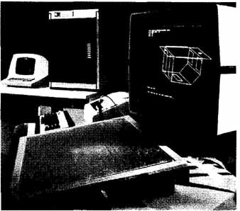
FIG. 25 Pictorial view of sheet metal enclosure. (Courtesy Computervision
Corp.)
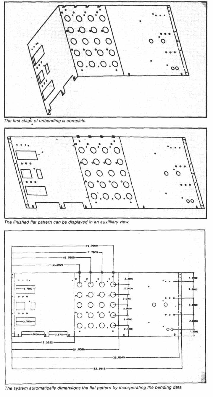
FIG. 26 Flat pattern development. (Courtesy Auto-Trot Technology Corp.)
SHEET METAL DIMENSIONING
When a sophisticated CAD program is used to design, layout, and detail a sheet metal part, dimensioning is completed automatically. The sheet metal heat sink in FIG. 27 was done with a CAD system.
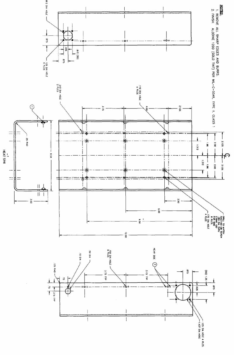
FIG. 27
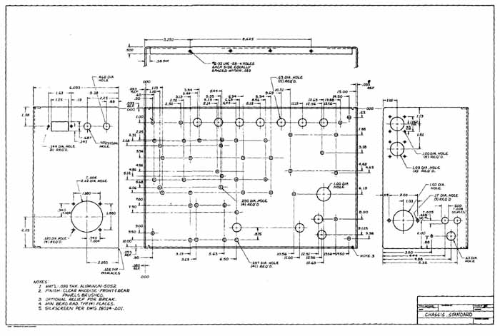
FIG. 28 Dimensioned chassis.
In most cases, sheet metal parts are designed and detailed by the traditional manual drafting techniques. In FIG. 24, the sheet metal chassis was drawn and dimensioned with fractions. The use of fractions for sheet metal drawings is a common American practice where there is no need for close tolerance fabrication and machining. The dimensioned chassis drawing shown in FIG. 28 and the mounting plate detail in FIG. 29 were hand drawn. These drawings were dimensioned with datum lines and rectangular coordinate dimensioning methods. FIG. 28 was dimensioned with a rectangular coordinate system without connecting dimension lines. The notes in the lower left-hand corner of the drawing give the material, finish, and bending radius for the part. The dimensions and text in FIG. 29 were completed with a Kroy lettering set.
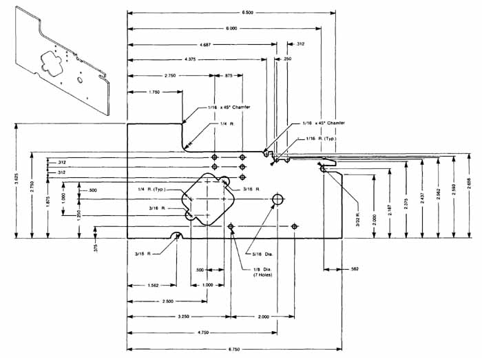
FIG. 29 Mounting plate detail. (Courtesy Ernie Schweinzger & Assoc.)
The methods and procedures presented in Section 4 should be closely adhered to for sheet metal layout drawings and all other types of enclosure, chassis, and cabinet parts regardless of material type. Note that the use of rectangular coordinate dimensioning without dimensioning lines but with hole charts expedites the programming stage when numerical control is used for the manufacturing process. Holing charts and coordinate dimensioning eliminate the need for calculating the lo cation of each hole, slot, or other feature, since the dimensions are taken from a predetermined datum or reference line established with a zero point and X—Y axes.
This process is especially beneficial when the part to be machined is a simple, flat (or thin), one-surface object with many holes and slot requirements, as in the mounting plate in FIG. 29. When the object is a typical rectangular, boxlike chassis with holes and slot cut outs on more than one surface, this process is also useful if the part is dimensioned and then machined as a flat pattern development. In FIG. 28. the part is projected as a multiview dimensioned drawing, not a flat pattern development. The dimensioning for the two sides is not datum line dimensioning as on the front surface. Possibly, the machining processes are to be completed after the part is laid out, developed, and bent to the final design configuration shown in the figure.
CHASSIS MARKINGS
In general, most chassis are marked for component placement and for general parts numbers. These markings are shown on the detail drawings where applicable. Silkscreening the numbers or other characters on the part is widely used. FIG. 28 provides the silkscreen specifications in the drawing notes: Silkscreen per dwg. 18014-201. Here, only the part number is marked on the part, not the component locations.
FASTENERS AND CONNECTION PROCESSES
Electronic packaging uses a variety of methods to fasten, connect, and attach electronic components, modules, and subassemblies to their respective chassis, mounting plates, panels, brackets, enclosures, and cabinets. The various metal and plastic enclosure parts are also fastened and connected with one another to form functioning units. The type of fastening or connection method must be determined by the use, function, environment, and life-length requirements of the equipment package.
Each of the different classifications of electronic and electrical items has different design specifications. Military equipment must be more rugged, vibration and shock resistant, and noncorrosive than industrial or consumer products. Space and satellite communications electronic equipment must withstand special environ mental characteristics, including excessive temperature, humidity, or pressure variations and weight restrictions. Commercial, military, and industrial products need to be easily disassembled for repair, servicing, and trouble shooting.
Fastening and connecting methods include permanent connecting processes; welding, brazing, soldering, riveting, bending/crimping. Fastening methods also include nonpermanent fasteners: pins, clips, spring locks, screws and bolts, nuts and washers. Methods that do not allow easy disassembly are considered permanent connections, and those that permit simple, quick disassembly are considered nonpermanent.
Welding may be any number of types, although spot welding and arc welding predominate. Spot welding is a commonly applied procedure for chassis and cabmetry assembly. In spot welding, pressure and heat are applied in the form of electric current to the two surfaces that need to be attached. Crimping may also be used in this process, or it may be used alone. Arc welding, soldering, and brazing are also used where the parts must be made into one unit. In FIG. 16, the chassis is to be formed from sheet metal and standard steel angle and channel shapes. The total unit is welded.
Rivets are a simple, quick, and inexpensive connection method used throughout the electronics industry. A wide variety of shapes and types of rivets is available. Rivets are ideal for joining aluminum or steel sheet metal parts. Rivet materials include aluminum, brass. and steel.
The type and variety of fastening methods found in the electronics industry are extensive. In FIG. 30, socket cap, flathead screws, and buttonhead screws are shown. The flathead and caphead varieties are shown flush with the upper part surface. The mounting bracket assembly detail shown in FIG. 31 uses bolts and nuts to secure the bracket and mounting panel. In FIG. 32, the isometric exploded pictorial provides an assembly view and parts list. The panel is secured to the bracket with (Phillips) flathead screws and speed nuts. Nuts and washers of all kinds are used to assemble electronic equipment. In FIG. 33, fastenings for military electronic equipment are provided along with their associated military standard. The table includes washers, pins, screws, and nuts.
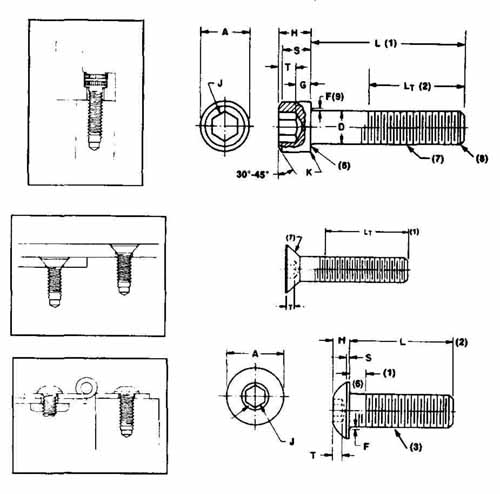
FIG. 30 Fasteners. (Courtesy Holo-Krome Co.)
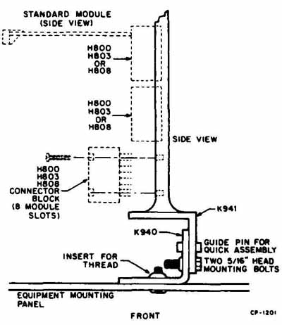 FIG. 31 Mounting bracket and fasteners. (Courtesy Digital Equipment
Corp.)
FIG. 31 Mounting bracket and fasteners. (Courtesy Digital Equipment
Corp.)
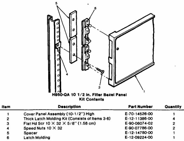
FIG. 32 Panel assembly and fasteners. (Courtesy Digital Equipment Corp.)
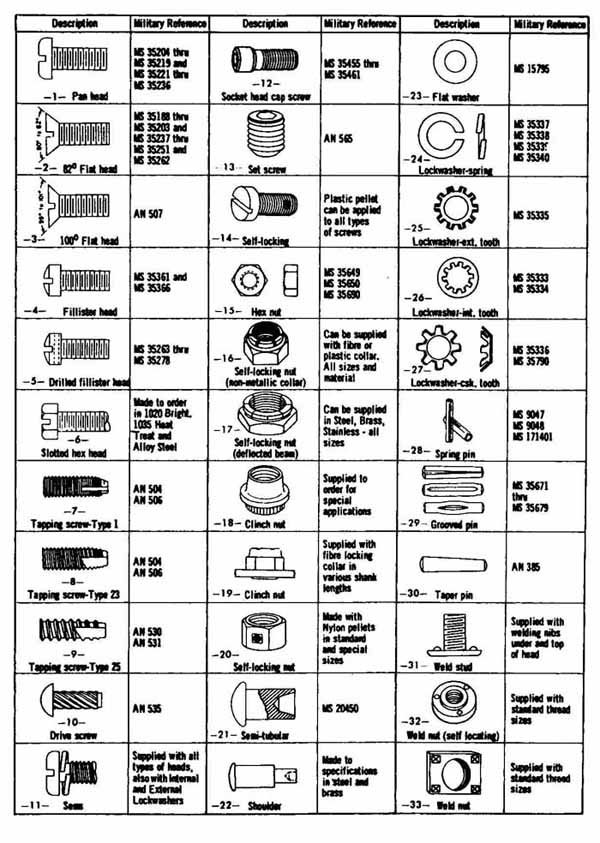
FIG. 33 Fasteners for military electronic equipment. (Courtesy of Federal
Screw Products, Inc.)
REVIEW QUESTIONS
1. Name four considerations in the design of electronic packaging.
2. Electronic products produced for the private sector are called:
a. Industrial c. Commercial b. Computer d. Military
3. Name four environmental considerations in the design of electronic packaging.
4. Cabinets for computer products are normally made of ( ), whereas military and communications cabinets are made of ( ).
5. True or false: A chassis is a sheet metal part on which electronic components and modules are mounted.
6. Name four items that are normally mounted on the front panel.
7. Flathead screws and socket head cap screws are used where the fastener must be ( ) with the mounting surface.
8. Name four methods of fastening or connecting.
9. Which fastening methods are considered permanent?
10. Sheet metal flat pattern developments are normally formed into their final design shape by ().
PROBLEMS
1. Redraw the chassis box shown in the accompanying figure. Develop the part and dimension completely. Scale the drawing from the text and assume that it is shown at ¼ scale.
PROBLEM 1 Chassis box. (Courtesy of J. Higgins)
2. Draw and dimension the base/tray in the accompanying figure.
3. Draw, develop, and dimension the mounting bracket shown,
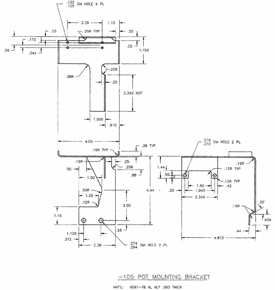
PROBLEM 3 Mounting bracket.
4. Draw, develop, and dimension the sheet metal part in the accompanying figure.
PROBLEM 4 Sheet metal part.
5. Make a full-sized development pattern for the chassis enclosure shown in Figs. 23 and 24. Use lightweight cardboard.
6. Draw the chassis shown in FIG. 28 and dimension it using a hole chart. Establish the location of holes based on view (right side, front, and left side) and datum line dimension. Use specifications from Section 4 for this project.
7. Draw the mounting plate shown in FIG. 29. Dimension the part with rectangular coordinate dimensions without dimension lines. Use a hole identification list. Use dual dimensioning.
8. Draw and dimension the heat sink in FIG. 27.
9. Draw the chassis shown in FIG. 16. Establish an X and Y axis and dimension using them as datums. For clarity, dimension lines may be eliminated.
10. Develop the sheet metal enclosure shown in FIG. 28 and dimension completely. Use datum lines and dual dimensioning.
11. Design a complete electronic package for the circuit selected by your instructor.
12. Design a chassis for the PC board selected by your instructor.