AMAZON multi-meters discounts AMAZON oscilloscope discounts
Because drawing for the electrical and electronics industry includes so many types of drawing, it utilizes all the various graphical techniques in one place or another, at one time or another. In the beginning stages of some projects, rough freehand sketches may be the most appropriate way to show ideas graphically. On the other hand, the final stages of some projects may require precision drafting that necessitates the use of sophisticated and expensive equipment.
This guide can provide only an overview of the various ways to make technical drawings. A small amount of instruction is provided in the use of the time-honored method of making drawings with triangles or T squares. In addition, the subject of freehand sketching (often a prelude to the construction of a drawing by instruments or computer) is presented from time to time in the guide. Most students will be able to develop a method to complete the drawing assignments made by their instructor, given the type of equipment available to them.
Computer-aided graphics is treated in Section 2. The bibliography contains a list of several excellent texts in engineering drawing, computer graphics, and related subjects. School libraries and college bookstores are likely to have books on technical or engineering drawing in case the reader wants to learn more about drawing techniques.
1. Line Work
FIG. 1 and 2 are examples of drawings done in the electrical and electronics industry. FIG. 1 is an older drawing that was made on a drafting machine and by use of a mechanical lettering device. FIG. 2 is a computer- generated drawing that was laid out on a cathode-ray-tube (CRT) console and then plotted on a belt-bed plotter. The lettering is from a font (alphabet) provided by the manufacturer of the computer graphics equipment. FIG. 3 is a drawing that was made by a student. The three orthographic views were obtained by use of drawing board, T square, and triangle. The lettering and arrows were drawn freehand. Freehand sketching was used to draw FIG. 4. It was made on a sheet having *-in. (6.35-mm) grid lines. Sketches such as this are used in several different ways; one is a preliminary layout for an instrument-produced drawing.
The drawings just discussed have one thing in common. The lines are almost all horizontal or vertical. There are quite a number of ways to make parallel lines, depending on the accuracy required and the equipment available. Some of these methods are:
1. With a plotting device such as the drum or belt-bed plotter
2. With a drafting machine
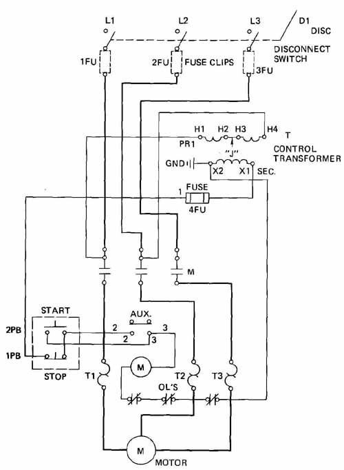
FIG. 1 An electrical drawing made by a professional drafter in U.S.
industry.
3. With a parallel straightedge, or bar
4. With special section-lining devices
5. With a T square (and triangles)
6. With two triangles
7. With tape appliqués
8. Freehand
In general, the cost of equipment and the accuracy obtained decrease as we go from 1 to 8 in the above list. FIG. 6 to 8 show some of the equipment listed. For small drawings, a second triangle can be substituted for the T square, although this is not as convenient as using the latter.
Different types of line are used for different purposes in electrical drawing. These are shown in FIG. 5. Some of the equipment that is used to produce electrical and electronic drawing is illustrated in Figs. 6 through 11.
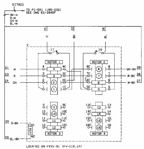
FIG. 2 An electrical drawing made with computer and related equipment.
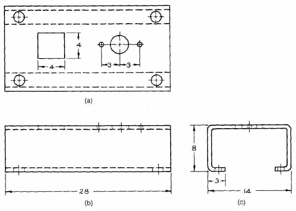
FIG. 3 A drawing made by a student. It contains three views of a chassis:
top view at upper left, front view at lower left, and right-side view
at lower right.
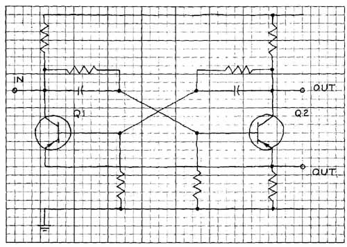
FIG. 4 A freehand sketch of a circuit schematic.
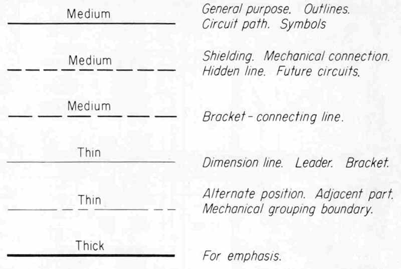
FIG. 5 Different lines and their uses in electrical and engineering
drawings.
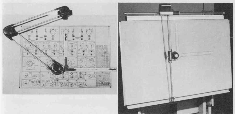
FIG. 6 Two styles of drafting machine. (Keuffel & Esser Co.)
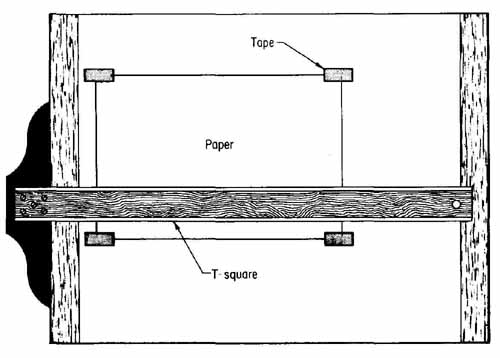
FIG. 7 Positioning of a small-size sheet of drawing paper on a drawing
board. The bottom of the sheet should align with the top of the T square.
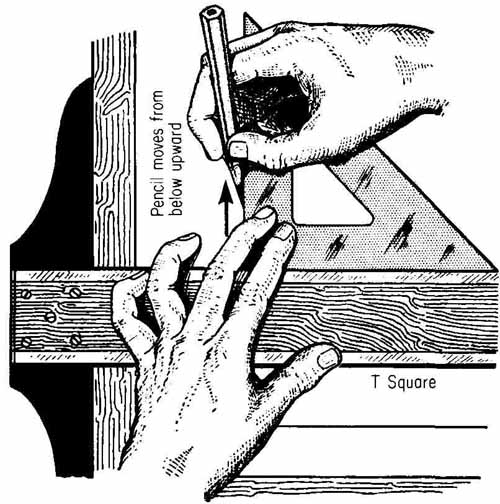
FIG. 8 Using a T square and triangle to draw vertical lines. The left
hand holds the T square so that the head is tight against the edge of
the board or desk.
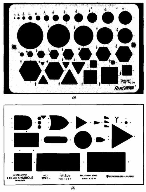
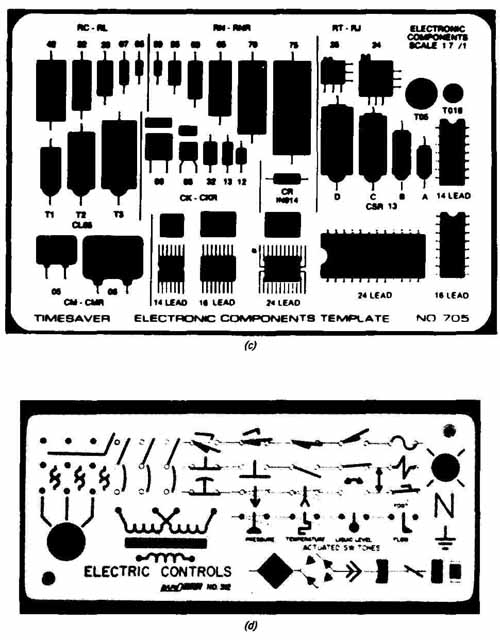
FIG. 9 Typical drafting templates: (a) template having geometric shapes
of different sizes (Berol Corp.); (b) a logic symbol template (Staedtler-Mars);
(C) electronics-component outline template (Timesaver Templates, Inc.);
(d) electromechanical control symbol template (Berol Corp.).
2. Circles, Symbols, and Other Shapes
Circles are generally made with the compass or with templates. Because circles in most electrical drawings are smaller than 1 in., templates are used more frequently than the compass for circle construction. Templates are flexible, thin (0.020- to 0.060-in.) pieces of plastic with generally accurate shapes punched in them. Many models are designed for the purpose of making geometric shapes such as circles, rectangles, triangles, etc.; while others, for use in electrical and electronic drawings, are for making symbols, component outlines, and wiring diagrams.
Over the years, designers and drafters accumulate a large collection of templates to do their drawings. Templates are a more convenient, faster, and more accurate method of drawing shapes and electrical symbols compared with conventional methods. For example, drawing a transformer symbol as in Fig. 3-11 would take several minutes by conventional methods, whereas drawing it using a template would take only 15s. (The times mentioned are those expended by one of the authors.)
Care should be used in selecting templates in terms of the quality, ac curacy, symmetry, arrangement of the shapes, and the shapes and symbols required. Many template manufacturers will make special templates upon request. FIG. 9 shows several templates that could be used in doing drawings. Figure 9a is a template having a variety of geometric shapes. Figure 9b is a logic-symbol template that is used for making logic diagrams. FIG. 9c is an electronic-components template used for making printed-circuit-board layouts and wiring diagrams. Figure 9d is an electromechanical-control-symbol template used in making control schematics. These are just a few examples of the many varieties of templates on the market today.
Several concepts should be followed in using a template.
1. In order to draw any geometric shape at the precise location desired, construct centerlines (along the axes, at least as long as the longest diameter of an equivalent circle) on the drawing before the template itself is positioned for the drawing of the shape. Many times, for small quick modifications to existing drawings, experienced designers use one line and an “eye-balled” centerpoint; however, this is not recommended for beginners.
2. For proper alignment, the template must be held firmly against a T square, drafting machine arm, or some suitable (horizontal) straightedge.
3. The pencil must be held vertically as the figure is being drawn. This is the only way to be certain of the correct alignment and shape of the figure. It may also be necessary to use a slightly duller pencil point than normal in order to achieve the desired line thickness of the figure.
4. During inking, the template should be slightly raised off the drawing medium by a template guide and a sheet of Mylar or tape should be fastened to the back of the template to prevent the ink from feathering. FIG. 10 shows the general procedure on how to use a template.
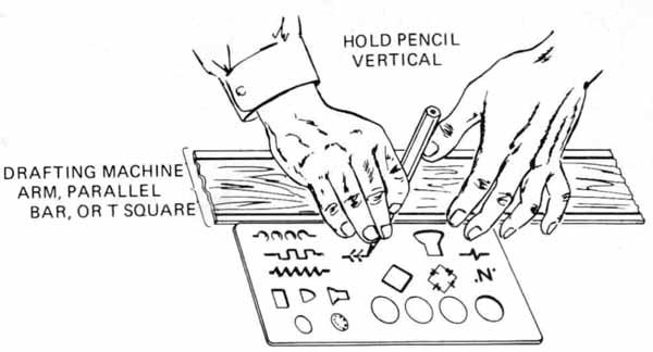
FIG. 10 Relationship of a template to a horizontal straightedge.
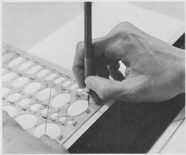
FIG. 11 Use of an ellipse template to make ellipses on a pictorial drawing.
FIG. 11 shows a drafter using an ellipse template. The drawing paper is taped to a drafting table, and the person is holding the template snugly against the top edge of the parallel bar straightedge. Short construction lines (horizontal and vertical) have been made on the drawing to correspond with marks printed on the template at each ellipse. The marks on the template are placed directly over the marks on the drawing. When this has been done the drafter does not have to guess where to position the template. Just about all templates have marks that enable the user to position the template accurately on a drawing.
In the case of circle templates these marks correspond to centerlines. Since the centerlines are usually used to locate holes in the first place, the marks are very useful. In electrical and electronics templates there are marks which correspond to the signal path, wire, and so on. These marks are helpful to the user in positioning the template correctly when making symbols or outlines.
Templates are very convenient for making shapes and electrical symbols; however, a designer should also know how to construct symbols with the basic drafting tools because the necessary templates might not be available. These procedures are covered in Section 3.
3. The Importance of Lettering
Electrical drawings utilize all the conventions and shortcuts of engineering drawings in order to present a graphical concept of devices or systems. How ever, the line work, symbols, and other patterns of a drawing are not sufficient to give the complete picture. Considerable lettering is required on most electrical and electronics drawings. FIG. 1 through 3 show the amount and kind of lettering required on an electrical drawing. Some drawings require even more in proportion to the amount of line work than these drawings. In many cases, as much time is used in doing the lettering on the drawing as is used in doing the line work. In drawings which are to be used for the manufacture, construction, or installation of equipment, lettering is often done freehand. In drawings that are to be used over and over again or in those which for certain reasons are to be printed in books, manuals, or journals, lettering is usually drawn with mechanical lettering devices.
In every case, lettering must be good. Poor lettering not only ruins the appearance of a drawing that is otherwise good but improves the chances of costly mistakes being made in the reading of the drawing. It so happens that the lettering in FIG. 1 was done mechanically, mainly because it was a part of a set of printed installation instructions. But before this final drawing was made, another one using freehand lettering had been drawn. Although mechanical and computer-aided lettering is becoming more prevalent, many electrical drawings still have freehand lettering.
4. Types of Engineering Lettering
Practically all the alphabets used in technical drawings are single-stroke Commercial Gothic. Four types of these single-stroke letters in use today are:
1. Vertical uppercase (capitals)
2. Inclined uppercase
3. Inclined lowercase (“small” letters)
4. Vertical lowercase
The alphabets above are arranged in what the authors believe is the order in which each type is used in U.S. industry, with type 1 used the most, type 2 the next, etc. One who wishes to become expert in the making of electrical or electronics drawings should be proficient in doing freehand lettering of type 1 and possibly types 2 and 3.
The person who has had no lettering instruction and wishes to become proficient at freehand lettering should practice one type of alphabet at a time. A logical sequence of alphabets would be (1) vertical uppercase, (2) inclined uppercase, and (3) inclined lowercase. With each alphabet the student should develop a set of numbers that appear to match or fit with the letters. As a rule, numbers are usually made narrower than the letters of the companion alphabet. Thus the number zero should be narrower than the letter O of the same alphabet.
5. Standard Alphabets
Lettering for drawings is standard throughout the United States. Three standardized alphabets are shown in FIG. 12. There may be slight differences between alphabets authorized by one agency and another, and also between alphabets shown in drawing textbooks, but these differences are minor. The shapes of the letters are, in general, the same.
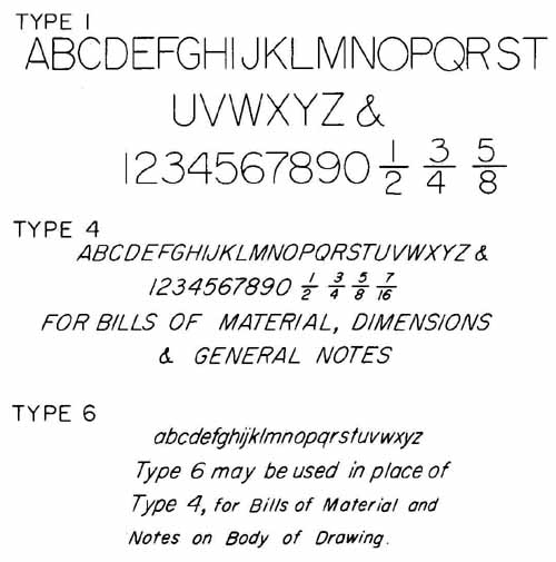
FIG. 12 Typical American National Standard (ANSI) alphabets.
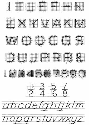
FIG. 13 Proportions and suggested strokings br letters. (From Thomas
E. French and Charles J. Vierck, Fundamentals of Engineering Drawing,
McGraw-Hill Book Company, New York, 1960.)
FIG. 13 shows vertical uppercase letters placed in blocks that are six small squares high. Borrowed from a famous textbook, this illustration shows the comparative widths of all letters and the suggested order of strokes for right-handed persons. This order does not have to be followed, but it is used by many drafters. Left-handers will probably have to develop their own order of stroking, using whatever is most comfortable and effective.
6. Guidelines
Practically all freehand lettering must make use of guidelines. These are very light, thin lines that locate the tops and bottoms of capital letters, numbers, etc. They should be just dark enough to see, because erasing them is not practicable after letters are penciled in; therefore, they should be as nearly invisible as possible.
There are a number of ways to draw guidelines. The most convenient way is to use a device especially made for that purpose. Two such devices are shown in FIG. 14. In this illustration, guidelines for capital letters have been constructed with both the Braddock and the Ames lettering devices. In the lower figure, lines have also been partially drawn for the bodies of lowercase letters but were stopped near the letter C and number 3. Guidelines may also be made with T squares and triangles in conjunction with scales.
Different combinations of letters and figures require different arrangements of guidelines. If only uppercase letters are to be used, just the top and bottom guidelines are necessary (see FIG. 15a). For lowercase letters, the intermediate, or “waist,” line must be used with the other two lines, as shown in FIG. 15b. A “drop” line may be placed below the baseline to facilitate making the descenders. This is not done very often, probably because the normal spacing provided by lettering devices does not allow enough space for drop lines. Occasionally it is desirable to have a line exactly centered between the upper and lower guidelines. This would be helpful, for example, when many fractions are part of a note (see FIG. 15c). Because fraction heights are usually made twice those of whole numbers and capital letters, additional lines may be added above and below, as shown at the right end of FIG. 15c. This would produce a series of lines all equally spaced. This type of spacing can be obtained with the Ames lettering instrument for nine different sizes of letters and with some models of the Braddock-Rowe lettering triangle for one size of letter.
FIG. 16 shows another type of freehand lettering guide that is easy and simple to use. Lettering guides of this type have a number (usually four) of guide slots for various heights of letters — ranging from to j in. Either inclined or vertical freehand lettering may be done using this type of guide with the assurance of uniform-height letters due to the upper and lower edges of the guide slots. A drafter can letter with great speed using this type of guide; however, care should be exercised to avoid flattening rounded letters against the edges of the guide.
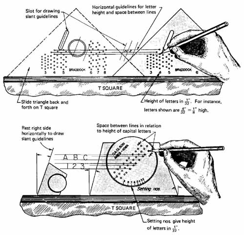
FIG. 14 Use of lettering guideline devices. (From Frank Zozzora, Engineering
Drawing, McGraw-Hill Book Company, New York, 1958.)
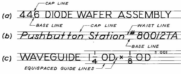
FIG. 15 Use of guidelines for different situations. Horizontal guidelines
for letter height and space between lines.
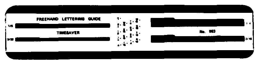
FIG. 16 Another device for making guidelines for freehand lettering.
(Timesaver Templates, Inc.)
Another way to align the tops and bottoms of letters is to use guidelines already drawn on a piece of paper. This paper is positioned under the sheet of tracing paper or transparent plastic material on which the drawing is to be made. The guidelines show through the drawing medium and are followed just as if they were drawn on the medium itself.
7. Parts Lists and Tables
FIG. 17 shows a part of a typical parts list, or bill of materials. In practice, the heavy horizontal dividing lines are usually spaced , 1/4, 5/16, or 3/8 in. apart, and the letters are made not more than one-half as high as this vertical spacing. One convenient way to organize such a list is to use equally spaced guidelines, as shown in the lower part of FIG. 17. For instance, if the lines are spaced 1/16- in. apart (using a lettering guide set for No. 4 letters, as in FIG. 14), letters and numbers will be 1/8 in. high and centered between the horizontal dividing lines, which will be ¼ in. apart. Abbreviations are frequently used; examples are CRS for cold-rolled steel and AL for aluminum. Capital letters are almost always used. Parts lists and other tabular arrangements often accompany, or are part of, electrical drawings. Their exact arrangements (formats) are not standardized.
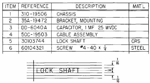
FIG. 17 Layout for a parts list, with suggested vertical spacing.
8. Mechanical Lettering Devices
A number of devices for making engineering letters mechanically have been successfully tried and used in the drawing room. They fall into two classes: (1) the stencil, or incised-letter, type, with which the drafter puts the letters on the drawing medium, and (2) the special typewriter, with which one puts the letters on the drawing after the drafter or engineer has written or otherwise indicated what material is to be typed. Examples of the first type are shown in Figs. 18 and 19. These can be used for penciled or inked letters. The fountain-pen type of lettering pen (the Rapidograph, for example) can be used with the stencil type such as that shown in FIG. 19.
Other ways to make lettering are the computer (or more specifically a computer and plotting system) and a special typewriter-like device called a lettering system. FIG. 20 shows two computer-generated alphabets called fonts and a set of letters made by a lettering system instrument. Some of the computer equipment is shown in Section 2. Helvetica is one of several types of lettering that can be generated on the lettering typewriter, which is easy to use. The specified words, or combinations of words and numbers, are produced on strips of paper that have adhesive backing. FIG. 21 shows a drafter putting some of this lettering on a block diagram. To make certain that the letters are horizontal, blue pencil lines (which don’t show up well in the photograph) have been made with the horizontal straightedge. The best lettering on electrical, electronic, and engineering drawings today is done with this system.
The authors feel that most computer-generated lettering leaves something to be desired. The plotter that does the printing moves so very fast that small, unwanted marks sometimes appear when the pen puts down or lifts up, line weights are not always uniform, and smears are easy to make during handling.
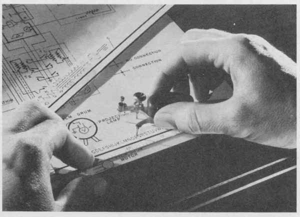
FIG. 18 A mechanical lettering device consisting of a template and a
scriber. (Keuffel & Esser Co.)
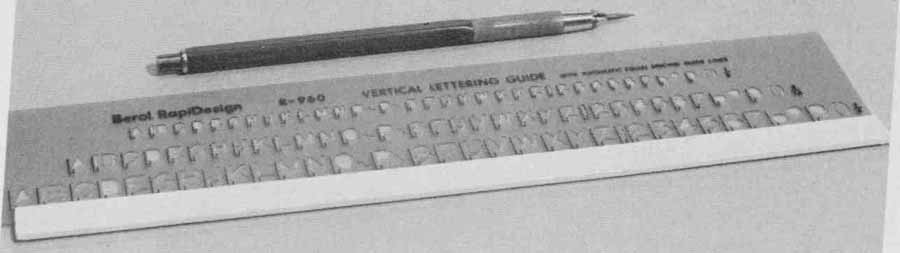
FIG. 19 A template used for making vertical uppercase letters 1/8, 3/16,
and ¼ in. high.
FIG. 20 Lettering produced by computer graphics equipment and the varityper. Alphabets produced by computer-driven equipment are called fonts. (a) RESFT is a standard engineering type letter. (b) CONDFT is a narrower letter. (c) Helvetica is a standard letter made on the Kroy lettering system. (d) Spacing produced by the computer-generated system. (Lines a and b by permission of Autotrol. Technology Corp. Fonts and spacing samples made by Black & Veatch, Consulting Engineers.)
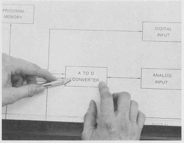
FIG. 21 Applying letters that were made with a lettering instrument
to a flow diagram.
Some of the letter and number shapes depart somewhat from the standard alphabet, usually not for the better. We have had to discard quite a few computer-generated drawings for illustration in the guide because of poor lettering, poor line width, or both. The fonts shown in FIG. 20 can be modified so that the crossbars can be removed from the land the shapes of other letters such as the W can be changed. According to the user, a large consulting engineering firm, a simple modification in the program would produce these changes. However, after using this equipment for several years the company has not yet seen fit to make the changes.
Yet another way to place letters on drawings is by transfer. Sheets of transfer letters, including such styles as Helvetica, Roman, and Old English, can be purchased in most college bookstores. These pre-printed letters can be positioned on a drawing and affixed to the drawing medium one by one by applying pressure on the desired letter with the blunt end of a pencil. They will stay on the drawing by virtue of their adhesive backing.
9. Orthographic Views (multi-view drawings)
Among the many types of drawing that are produced and used within the electrical and electronics industry are those that show the front, top, and side views (or maybe just two, or as many as five views) of an object. In manufacturers’ catalogs one often finds drawings of this type for certain devices or equipment. Or the designer of new products may sketch out or lay out with instruments several views of the object being designed, and the drafter may be required to make the finished scale drawing.
One such drawing is shown in FIG. 22. This is an outline drawing consisting of three views: a left side view at the left, the front view to the right of the left side, and the top view directly above the front view. This is the standard way these views are arranged (in the United States). Except for the front view of the notch, hidden lines are not shown. They are seldom shown in outline drawings. In this particular example dimensions are placed in the standard manner, using two-place decimals, with all digits horizontally oriented. It was drawn to a scale of 1 in. = 0.20 in. with a 20 scale. It appears in a reduced size in the book; therefore, it cannot be scaled, although the 30 scale comes close.
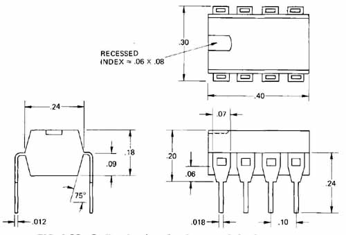
FIG. 22 Outline drawing of an integrated circuit package.
Another example is given in FIG. 23. This is a complete double-view drawing, consisting of the front and right-side views, or left-side and front views, whichever view the drafter and viewer consider to be the front view. (If the name of the view is important, each one could be labeled.) The writer has considered the view at the left to be the front view of the bracket; this means that the other one is the right side view. (FIG. 24 shows the correct location of four orthographic principal views). The bracket was drawn to full size using a metric scale, and the dimensions have been given in centimeters to two decimal places. In this guide the bracket has been reduced and cannot be scaled. Hidden lines (dashes) show the thickness of the 16-gage (0.062-in.-thick) steel including holes (see the side view). All dimensions have been shown except for the bottom holes, which are designated in a note at the bottom. A third view (looking down or up) might make the shape of the bracket a little more clear. But two views are all that are really necessary for the manufacture of the bracket.
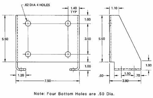
FIG. 23 Orthographic views of a mounting bracket.
FIG. 24 shows four different orthographic views of an object. Each corner has been labeled in all four views. The reader should note that the front surface, A B CD, is placed nearest to the front view in the side and top views. If the object were a car or an aircraft, the right side, B 2 3 C, would be what we normally call the left side of the car or plane. The right side view in this type of drawing means the view is seen from the viewer’s right, as if one moved to one’s right 90-degree around the object and drew it as seen from that position.
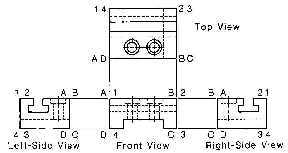
FIG. 24 Four principal views of a block with a T slot. Each corner has
been lettered or numbered.
In drawing principal views one generally lines up the two or three views with a T square, parallel straightedge, or drafting machine arm or triangle and usually works back and forth between views. In other words, it is not efficient to draw one view completely, then another view completely, then another, and so on. The drafter should take advantage of the fact that certain features line up (or align) in two or three views. Note the T shot in the side views and front view of FIG. 24. The amount of space needed between the views must also be determined. This depends largely on how many dimensions are to be placed between views. In FIG. 22 the front and left side views were drawn 2 in. apart; in FIG. 23 they were l in. apart on the original drawing. If the objects are not to be dimensioned, a distance that appears pleasing to the eye should be used. For drawings on 8+ X 11 in. paper an inch or a little more is usually about right.
10. Pictorial Drawing
As the electronics and electrical fields continue their phenomenal expansion, more and more devices that require pictorial representation, either in place of or as additions to standard orthographic projection, are encountered. Also, electrical drawings are being read by some technical personnel who have not had training in the reading and making of engineering drawings. These are two factors which have been responsible for the increase in the amount of pictorial drawing being done in the electrical industry.
Good examples of pictorial drawing applied in the electrical field are those used by the armed forces, maintenance personnel, assembly-line workers for assembling electronic equipment, and companies who manufacture do-it- yourself kits. FIG. 25 is a typical example of the latter.
FIG. 25 A pictorial drawing used for the assembly of a robot. (Heath
Company, Copyright © 1982.)
The types of pictorial drawing most often found in the electrical field are:
1. Isometric drawing
2. Oblique drawing
3. Dimetric drawing
4. Perspective drawing
Brief treatment of the first two categories of pictorial drawing will follow. References will be given for the more complicated subject of perspective drawings.