AMAZON multi-meters discounts AMAZON oscilloscope discounts
11. Isometric Drawing
[Liberal translation of the word isometric from the Greek gives “iso,” meaning “the same,” and “metric,” meaning “measurement.”]
It is conveniently possible to draw an object at such an angle or position that all edges will be foreshortened equally. For example, all lines of the cube shown in FIG. 26 have been drawn to the same length; that is, they have been foreshortened equally. This drawing, called an isometric or isometric projection, was obtained by using three axes, as shown in Fig. 26b. Rectangular-shaped objects lend themselves readily to this type of drawing because all lines, or edges, are drawn along or parallel to the three isometric axes and can be scaled directly.
A simple and direct way to make an isometric drawing of an object composed of rectangular-shaped surfaces is to draw an outline of a cube or prism and then measure off distances from edges of this cube to the corners and edges of the object. Such step-by-step procedure is shown in FIG. 27.
The front and top views of a transistor are shown in FIG. 27a. The major dimensions (in millimeters) are included. Using the box method, we begin by constructing a rectangular box or prism that has the overall height, width, and depth dimensions (excluding the three pins) shown in FIG. 27b. We have chosen to orient the device as shown in the successive figures to show it to the best advantage, but it is possible to orient it differently. In Fig. 27c we have cut out part of the right side of the block leaving the lower 1.2-mm-thick (or high) part as shown. In Fig. 27dwe have begun to locate and lay out the hole and the two semicircular cutouts. The isometric “diamond” within which the ellipse will fit has sides that are equal to the diameter of the 3.6-mm-diameter circle. But it is necessary to locate the center A by measuring “in” 5 mm from the front or back edges and 3 mm from the right edge, measuring along the isometric axes. (All measuring must be done along these axes.)
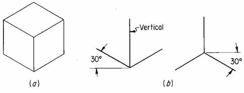
FIG. 26 An isometric drawing of a cube and the isometric axes.
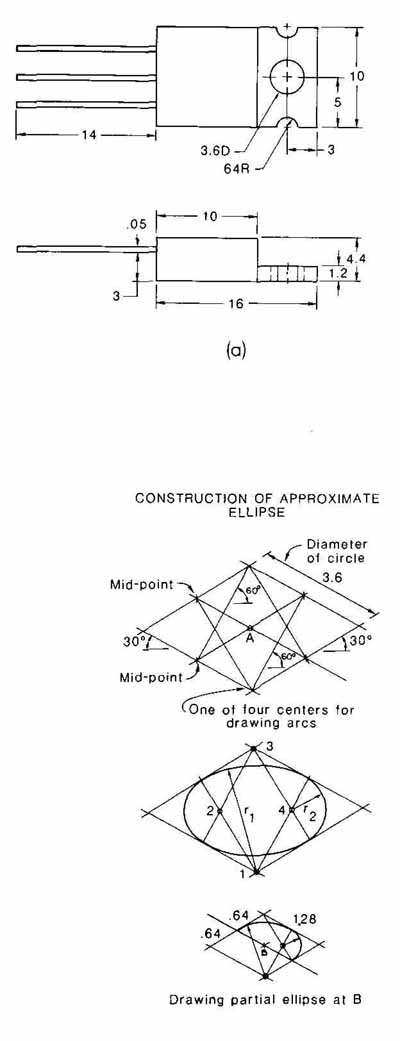
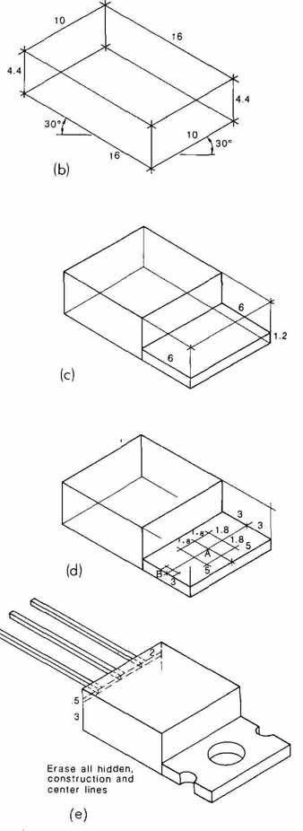
FIG. 27 (a) Front and top views of a transistor, (b) through (e) Step-by-step
construction for making an isometric drawing. Lower left: drawing an
isometric ellipse using the tour-center method.
There are several ways of drawing ellipses, three of which are (1) freehand; (2) with a drafter’s ellipse template; and (3) with the use of triangles, pencil, or pen and compass. Freehand curves appear unattractive on an instrument drawing; therefore, one should use an ellipse template that makes 35-degree ellipses, or triangles, compass, etc. Ellipse templates are very nice, but fairly expensive. For this reason, we have shown in the lower left part of FIG. 27 how to draw a horizontal ellipse and a partial ellipse by the four-center method. The main idea is to draw the diamond at the right location and to the right size, then to locate the midpoints of each side, and then to draw a line to each midpoint from the upper and lower corners to opposite midpoints. This construction completes the location of the four centers, 1, 2, 3, and 4 (see the second figure). The four arcs, with radius either r or r are then drawn tangent at the midpoints.
We have completed the isometric pictorial of the transistor in FIG. 27e, by drawing another s of ellipses 1.4 mm lower to show those parts of the curves on the bottom surface that can be seen. The leads have been added by measuring up 3 mm from the bottom on the left end and 2 mm “in” from the front and back sides for the outer two leads and then centering the middle lead. We have shown part of the leads with hidden lines. But these, as well as the construction lines, would be erased and should not appear in the final drawing.
Isometric drawings may be made with instruments (the 30-60 triangle is a natural choice) or drawn freehand. If an instrument drawing is to be made, any suitable scale may be used, and only the one scale selected will be used in making measurements along all three axes. Hidden lines are seldom shown. Dimensions may be added if necessary.
A freehand sketch of a chip carrier is shown in FIG. 28. It was made on specially prepared paper on which light grid lines had been printed in the direction of the three isometric axes. Most edges of a rectangular-shaped object can be drawn directly over the preprinted lines. Sometimes, however, a drafter might have to draw between — and parallel to — lines. These lines (usually in color) are generally in. apart and can be used as a sort of scale so that the person making the sketch can execute a sketch having the correct proportions.
To show the rounded edges on top, parallel broken lines have been drawn. Technically they aren’t necessary, but they are often used. Other methods are available but are not discussed here.
Another example of isometric drawing is shown in FIG. 29. Shading has been added to make this object look a little more like a photograph. A good isometric drawing does not have to have shading, however. Note that the plus and minus signs have been drawn along isometric axes.
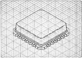
FIG. 28 Freehand sketch of a chip carrier.
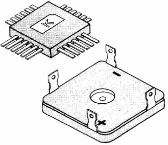
FIG. 29 An isometric drawing of an older flat pack and full-wave bridge
rectifier.
12. Oblique Drawing
Another type of pictorial representation which is easily made is oblique drawing, or oblique projection. In this type of drawing, one face of the object is drawn in its true shape and the other visible faces are shown by parallel lines, or projectors, drawn at the same angle (usually 30 or 450) with the horizontal.
In FIG. 30 a cube has been drawn in oblique pictorial projection with projectors going back at 30 and 45°. Any angle other than 0 or 90° can be used, but 30 and 45-degree are popular because they can be easily drawn with the use of triangles. There is a certain amount of distortion in an oblique drawing which is reduced when cabinet drawing is employed. This can be seen in Fig. 30c, in which the projectors have been made one-half as long as in the other two cube drawings. FIG. 30c looks more like a cube than do Figs. 30a and 30b.
The rectifier (FIG. 31) is suitable for oblique drawing for two reasons: (1) the face drawn perpendicular to the line of sight (in the plane of the paper) contains circular parts which can be drawn with a compass or circle template; and (2) the other axis is comparatively short, thus making it unnecessary to shorten the projectors. The projectors of the rectifier were drawn 45 degrees to the left and are not foreshortened. If the rectifier were drawn in the isometric manner, they would have been drawn at a 30 degree angle and all circles and arcs would have to be drawn as ellipses or parts of ellipses. The rectifier has also been drawn in cabinet projection in FIG. 31 c. Like isometric drawings, oblique drawings may be made freehand or with instruments.
A freehand sketch of a seven-segment light-emitting diode (LED) is shown in FIG. 32. This sketch was made on a sheet of paper without any aids. An instrument drawing of a transistor with radiator is illustrated in FIG. 33. In FIG. 33 the circles and arcs were drawn with a compass because they are in the plane of the paper. Orientation of objects in oblique pictorial drawing can often circumvent the need for drawing circular parts as ellipses.
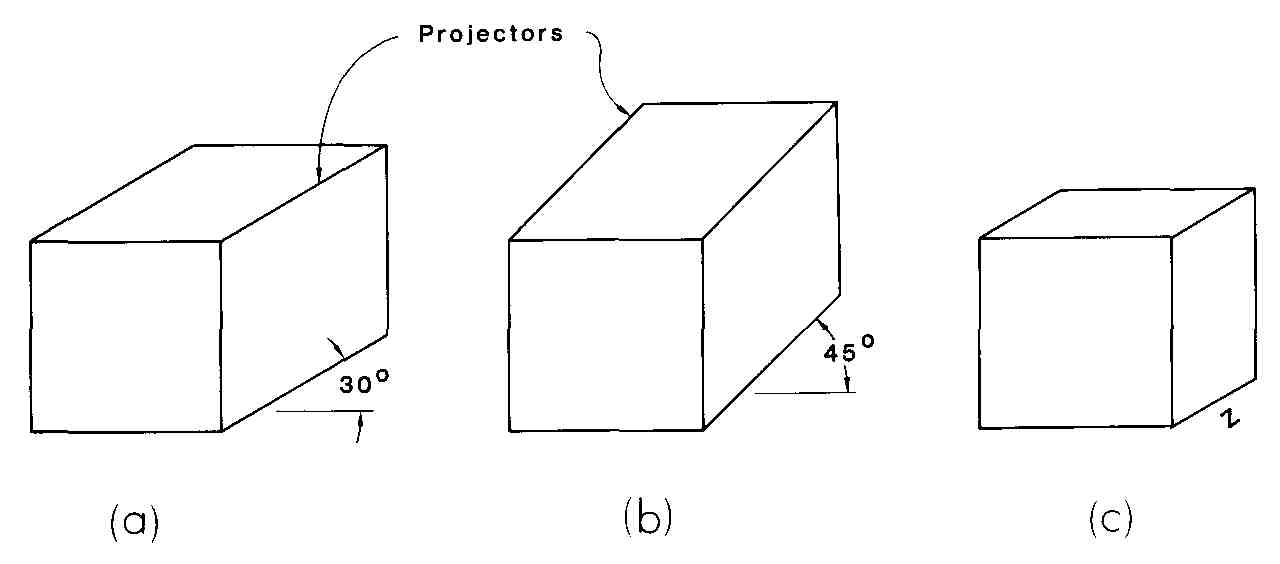
FIG. 30 Oblique view drawings of a cube: (a) with projectors to the
right and 30 (b) with projectors at 45 (C) cabinet drawing with the projectors
half as long as the other edges.
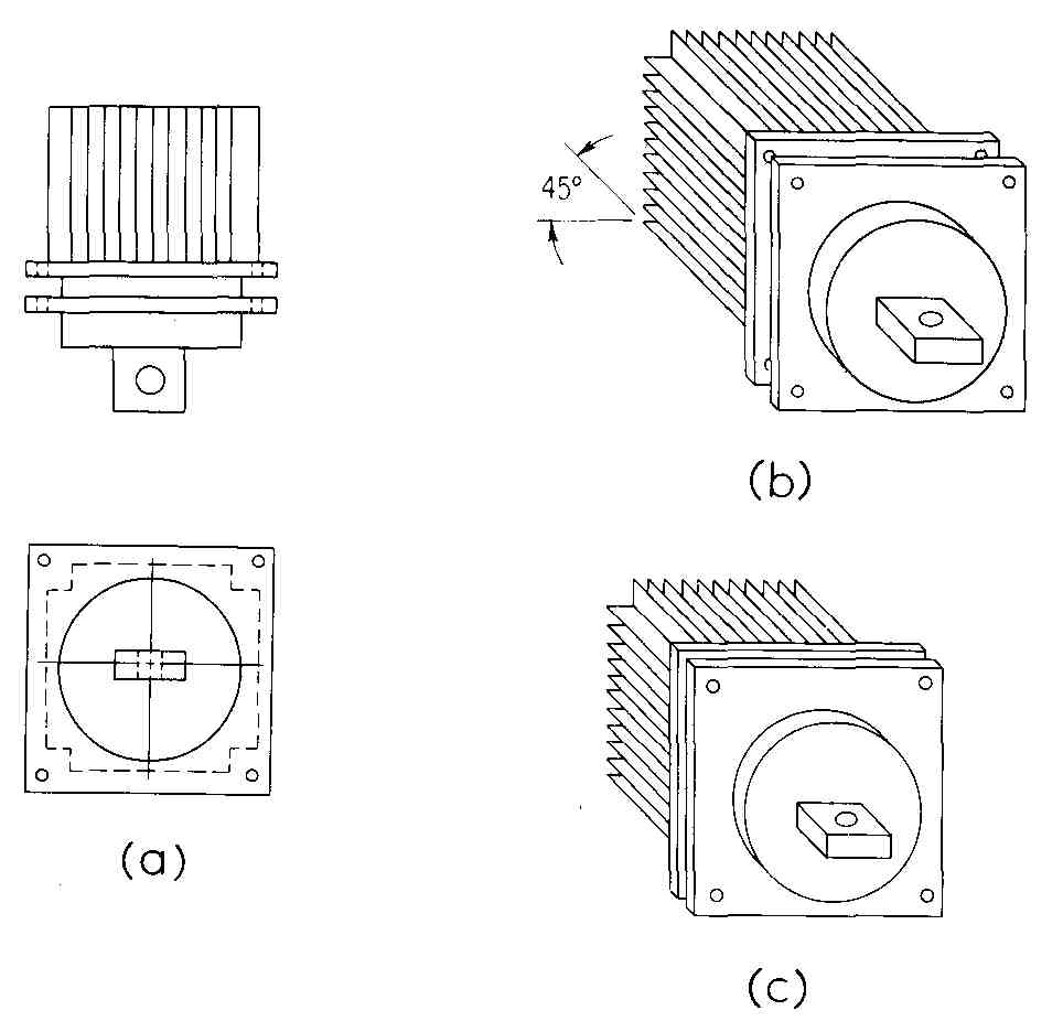
FIG. 31 Oblique drawing of a rectifier: (a) front and top views; (b)
oblique drawing with projectors left and 45 (C) modified oblique (cabinet)
drawing.
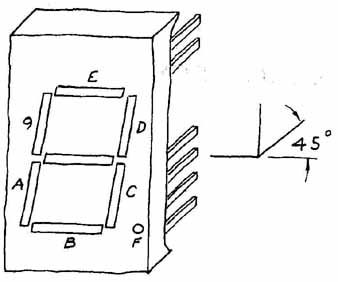
FIG. 32 A freehand oblique sketch of a seven-segment LED.
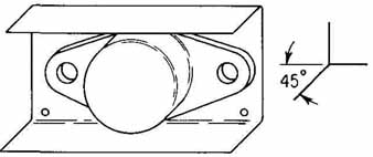
FIG. 33 An oblique instrument drawing of a transistor with a heat radiation
attachment.
13. Dimetric Projection
Another form of pictorial representation similar to isometric drawing is di- metric drawing, or dimetric projection. In this type of drawing the reference cube is viewed from such an angle that edges on two axes are equally foreshortened. The third axis (the lines marked 3 in Fig. 34a) is shortened a different amount, however, and thus cannot be measured with the same scale that is used for the other two axes. Examples of dimetric drawing are shown in FIG. 34. Dimetric drawing is not as popular as isometric and oblique drawing for two reasons: (1) difficulty is encountered in drawing circular parts as represented dimetrically, and (2) it is necessary to use two different scales when laying out a dimetric drawing. However, a dimetric drawing will produce a less distorted, more pleasing effect than will either of the other two types of drawing.
14 Perspective Drawing
The three methods of pictorial representation described thus far in this section produce only approximate representations of objects as they appear to the eye. Each type produces varying degrees of distortion of any device or system so drawn. Because of the ease and quickness of their execution, however, they are the types of pictorial drawing most often used in the electrical industry.
On certain occasions, the exact pictorial representation of an object as it actually appears to the eye may be necessary or desirable. Such representation requires that the principles of perspective drawing be observed. An example of such a drawing is shown in FIG. 35.
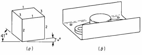
FIG. 34 Dimetric drawing: (a) cube; (b) TO-66 transistor can with radiator.
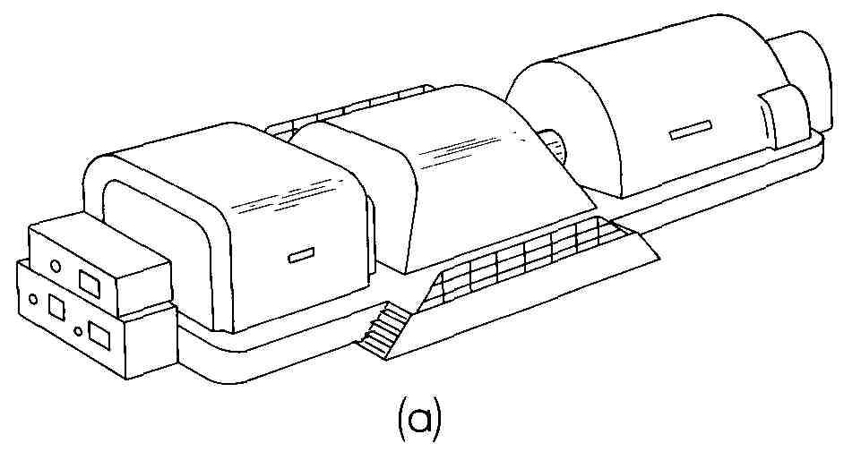
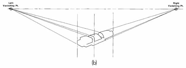
FIG. 35 Perspective drawing: (a) a steam turbine generator; (b) outline
drawing with horizon and vanishing points.
In FIG. 35b an outline of the turbine generator has been drawn with the horizon and two vanishing points included. Several lines go to the vanishing points from the machinery. An experienced drafter can orient the object men tally and locate the horizon and vanishing points. Other ways to locate the horizon and vanishing points are to (1) use a commercially prepared perspective grid something like the isometric grid on which the chip carrier was sketched; (2) use an exact approach applying top and side views and a picture plane at 90° to the desired viewing direction; and (3) start with an isometric, oblique, or dimetric sketch and then modify it by making sets of lines converge at their respective vanishing points.
Perspective drawing is a time-consuming process which requires more explanation than can conveniently be given in this guide. Most texts on engineering drawing cover this subject.
15. Pictorial Sections
Occasionally, the interior detail of a device can be appropriately shown by means of a pictorial section. All types of pictorial views— isometric, oblique, and perspective — can be used to show unusual interior details with full sections, half sections, or broken-out sections.
FIG. 36 is a section view showing the construction of a typical silicon point-contact diode. It is a full isometric section, in which the main axis is horizontally oriented. This is in contrast to the other isometric drawings in this section in which this axis has been drawn in a vertical position.
The same figure also illustrates the fact that standard section-lining (cross-hatching) symbols are not always adequate for electrical and electronics drawings. There is no standard section symbol for silicon. The silicon slice in this case was not section-lined. Each material has been labeled — a necessary, or at least highly desirable, feature when the American National Standard (ANSI) section symbols are not used throughout.
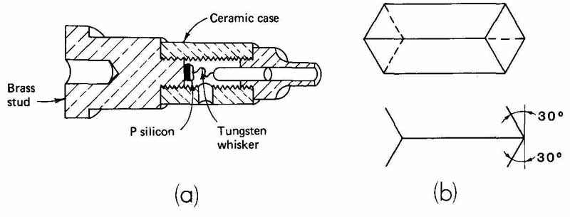
FIG. 36 (a) An isometric section of a diode; (b) views of a right prism
from or with which the diode might have been drawn.
16. Hidden Lines and Centerlines
Hidden lines and centerlines are seldom drawn in pictorial drawings. This is because pictorial views are intended to show the object as it is actually seen, and hidden parts are not seen. However, hidden lines may be shown if special hidden details are desired to be shown, and centerlines may be required if an object is to be dimensioned.
17. References
More detailed explanation of the construction required for oblique, isometric, and dimetric views, as well as perspective, may be found in the reference books listed in the Bibliography at the end of the guide.
SUMMARY
The techniques of making drawings for the electrical and electronics industry are the same as those used in making other engineering or technical drawings. With proper study, practice, and equipment nearly any person who has the desire can make most types of electrical drawing. The student having the least amount of equipment will have to work harder and longer than the person who has more sophisticated tools.
Good freehand sketching can be developed and used as an aid to lay out a drawing in the early stages. One can learn to letter well by practicing fundamental strokes and learning the shapes of standard technical lettering. There are several types of mechanical equipment that make standard lettering; however, these are rarely available to the student.
Examples of typical drawings presented in this section are one-line wiring diagrams; schematic diagrams; material parts lists; orthographic (multi-view) drawings; and isometric, oblique, and other pictorial views. Many of these areas are covered in more detail in later sections. Problems at the end of this section are of several types and have been developed with the beginning drafting student in mind. But there are some that are appropriate for the person who has had previous drafting instruction or experience.
QUESTIONS
1. List five different ways of drawing parallel horizontal lines.
2. Why is it necessary to have different line weights and different types of lines in technical drawings?
3. List several ways to draw circles.
4. Show by means of a sketch the proper position of the top, left side, front, and right side views of a cube.
5. If the horizontal dividing lines in a parts list are in. apart, what would be an appropriate height for the letters and numbers to be put in that space?
6. What lettering do you think is used the most in electrical drawing: vertical (roman) lowercase, inclined (italic) lowercase, vertical uppercase, or inclined uppercase?
7. In addition to making capital letters of a uniform height, how do we strive to achieve uniformity in lettering?
8. What is a font?
9. Why are dimensions placed on a scale drawing of an item of equipment?
10. What determines how far apart the views should be placed on a multi- view (orthographic) drawing?
11. What is the advantage of making an isometric drawing over a dimetric drawing?
12. What is the advantage of a cabinet-type drawing over a standard oblique drawing?
13. Identify a situation in which there would be an advantage in making an oblique drawing instead of an isometric drawing.
14. Can dimension lines be added to an isometric drawing?
15. List three ways to draw an ellipse.
16. At what angles (with the horizontal) are the “projectors” of an oblique drawing usually drawn?
17. What is the purpose of vanishing points in a perspective drawing?
18. In terms of using a scale, what is the advantage of making an instrument isometric drawing?
19. Why are hidden lines seldom shown in a pictorial drawing?
20. What is the purpose of hidden lines in a multiview (orthographic) drawing?
PROBLEMS
1. Referring to FIG. 37, make a scale drawing of the cover for a car AM/FM radio to full size. Use the English system of measurement (upper figures) or the metric system (lower figures), whichever your instructor specifies. The small holes are 0.16 in. (4 mm) in diameter, and the large holes are 0.50 in. (13 mm) in diameter. Put dimensions on the drawing if your instructor requires this. Use 8 X 11 paper.
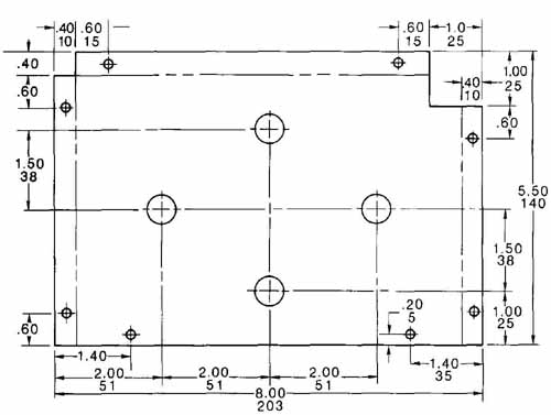
FIG. 37 (Prob. 1.) Scale drawing of car radio cover plate.
2. The major elements of a clock circuit are shown in FIG. 38, with scales along two edges having marks - in. apart. These marks can be used to layout the block diagram on a sheet of 8+ X 11 paper. Make neat uppercase letters that will fit in the block and numbers and letters identifying the lines between output part and clock chip.
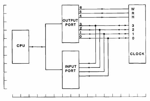
FIG. 38 (Prob. 2.) Diagram of a clock circuit.
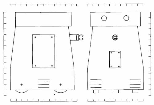
FIG. 39 (Prob. 3.) Left side view and front view of robot.
3. Two views of a robot are shown in FIG. 39. Marks around the edges are - in. (1 cm) apart and may be used for drawing purposes. Draw either view or both, whatever your instructor assigns. Small crosses in the side view show the centers of the three wheels, one in front and two in the rear (one view on 8+ X 11 paper).
4. An elevation of the receiving tower for a central solar collector is shown in the left part of FIG. 40. Dimensions are in meters. Two details are shown at the right. Draw an elevation of this tower and show the major dimensions that are indicated on the elevation. Use 8+ X 11 paper.
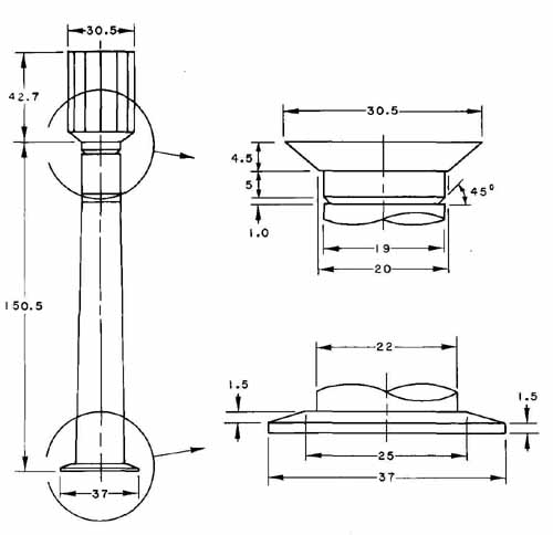
FIG. 40 (Prob. 4.) Elevation view of central receiving tower for solar
electric power generating station.
5. FIG. 41 is the layout of the cover for a smoke alarm. Make a scale drawing of this cover. Dimensions are in inches. Use the alternate position line (FIG. 5) for the fold lines. Use 8+ X 11 paper.
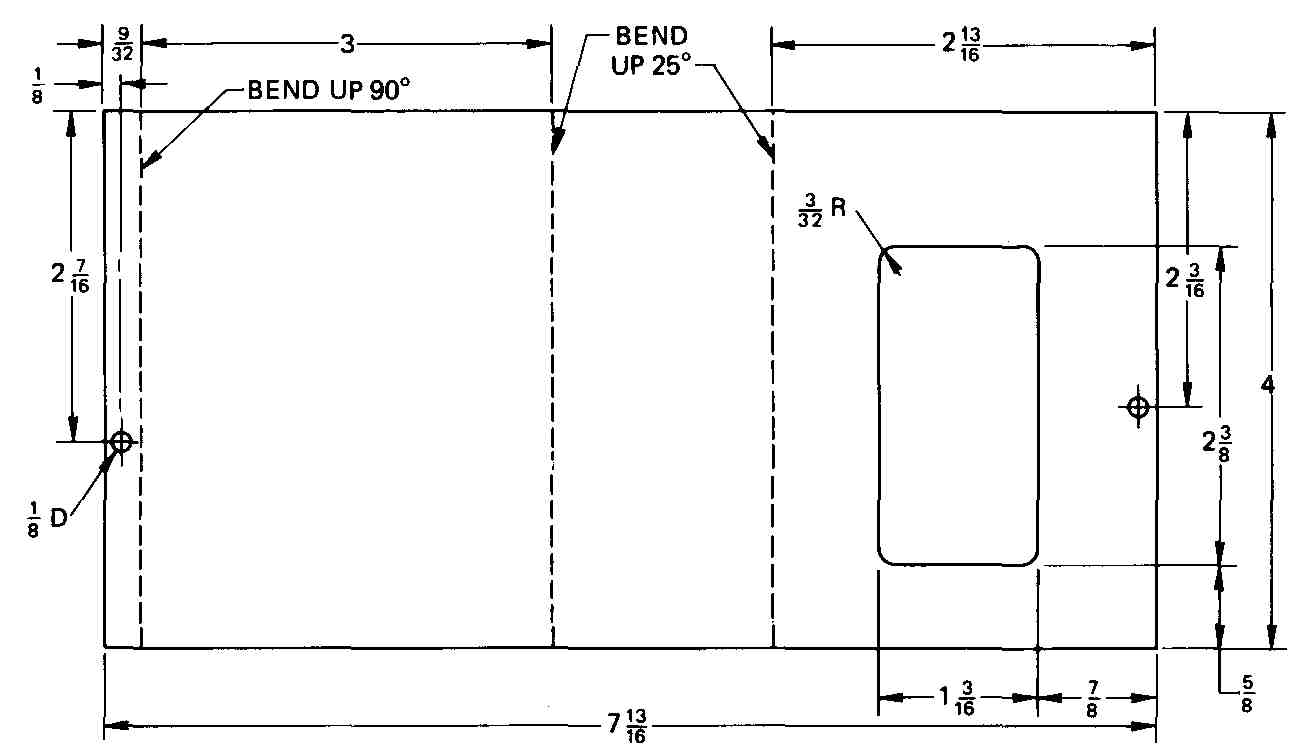
FIG. 41 (Prob. 5.) Cover for smoke alarm chassis.
6. Make a drawing of the photodiode shown in FIG. 42. Include the lettering (on 8+ X 11 paper).
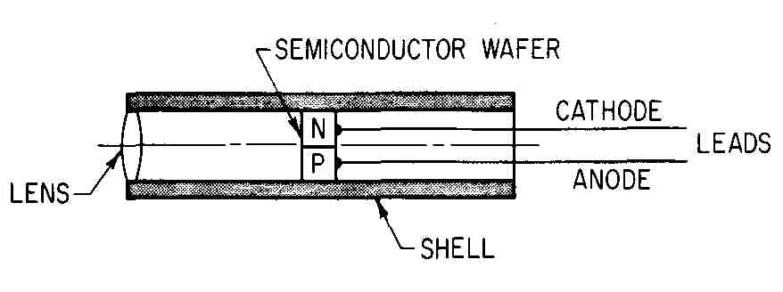
FIG. 42 (Prob. 6.) Diagram of a section of a photodiode. The length
is 4 times the diameter.
7. Make a drawing of the third rail section shown in FIG. 43. Where dimensions are not given, make your shapes as close to those shown as possible. Add lettering and dimensions if required by your instructor. Use 8 X 11 paper.
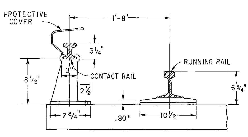
FIG. 43 (Prob. 7.) Section showing the third rail detail of a mass
transit system.
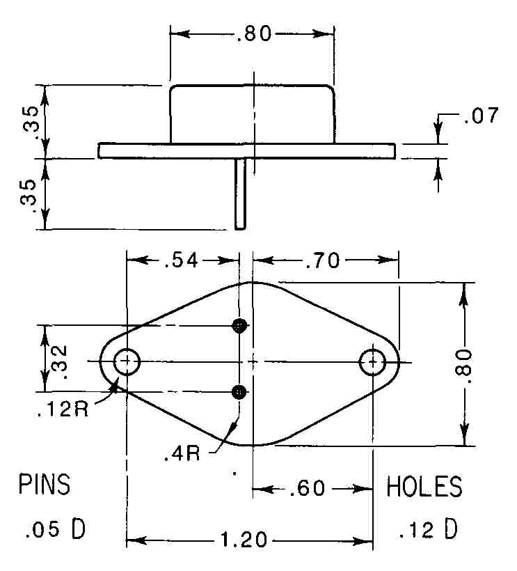
FIG. 44 (Prob. 8.) Outline drawing of TO-3 diode package.
8. Make an outline drawing of the diode shown in FIG. 44. Use an enlarged scale so that this drawing will fit on an 8+ X 11 sheet or so that it and Prob. 9 can both be put on an 8+ X 11 sheet. Dimensions are in inches.
9. Make an outline drawing of the transistor shown in FIG. 45. Use an enlarged scale so that this will fit on an 8+ X 11 sheet by itself, or with the diode from Prob. 8.
10. Make a two-view outline drawing of the microprocessor socket shown in FIG. 46. Dimensions are in inches. The pins are 0.20 in. apart (across) and pins and holes are 0.10 in. apart (center to center) in the long dimension. Use 8
11. Make a two- or three-view drawing of the integrated circuit package shown in FIG. 47. Use an enlarged scale so that the drawing will fit on 8+ X 11 paper. Dimensions and title may be added if the instructor so specifies. Tops of pins are 0.015 in. wide.
12. Make two or three views of the subchassis shown in FIG. 48. It may be shown as a development or formed as shown. Hole diameters are: No. 1,40; No. 2,7.5; No. 3, 18; No.4,7.5; and No. 5,7.5 mm. Material: SAE 1020 steel. Add notes: Break all sharp edges, remove all burrs, degrease per Spec. 51606, bright dip per Spec. 51606. All dimensions are in millimeters. (Two views, 8+ X 11.)
13. The dimensions of the mounting bracket shown in FIG. 49 are in inches. It is made of 16-gage (0.062-in., 1.6-mm) SAE 1020 steel. The thickness may be exaggerated as you draw two orthographic views on 8+ X 11 paper. Dimensions may be added if your instructor so directs. The bottom four holes are 0.50 in. in diameter.
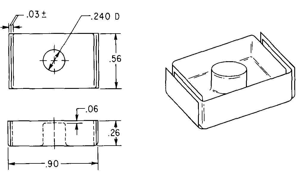
FIG. 45 (Prob. 9.) Front and top views of a TO-5 transistor “can”
with heat radiation attachment.
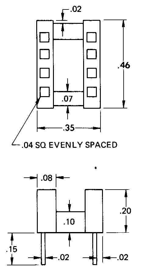
FIG. 46 (Prob. 10.) Outline drawing of a socket for a microprocessor.
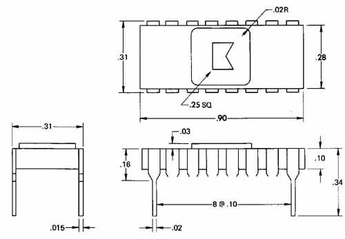
FIG. 47 (Prob. 11.) Outline drawing of 16-pin DIP ceramic case
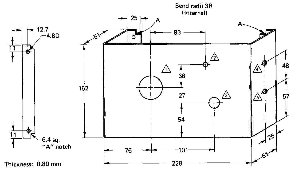
FIG. 48 (Prob. 12.) Pictorial and partial view of a subchassis.
14. Note: Four Bottom Holes are .50 Dia.
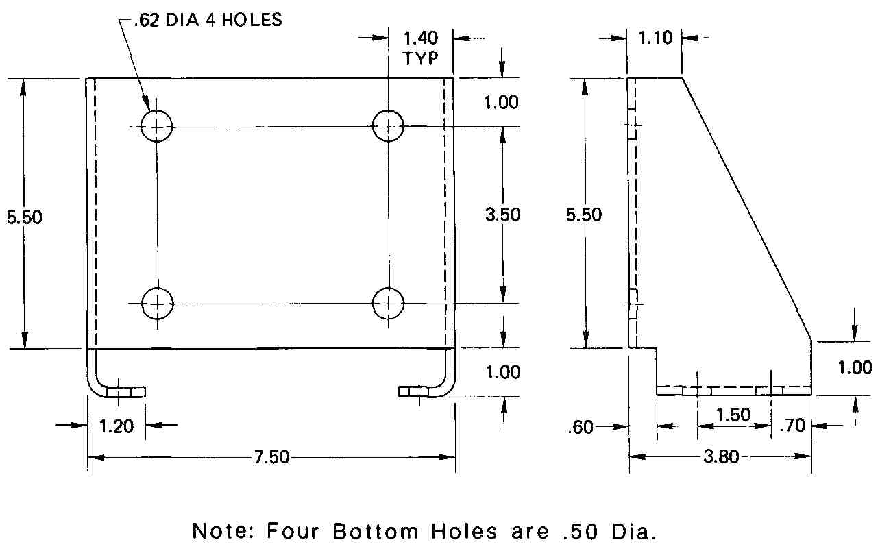
FIG. 49 (Prob. 13.) Two views of a mounting bracket.
15. With -i-in. uppercase letters, letter the following:
a. Clock enable
b. 90 mW across 50-a load
c. MC 1488 pin 14
d. All resistors are - W ± 5 percent
e. V = 4.75 V
16. In a space of about 6 X 12 cm make a set of general notes as follows:
Resistance values in ohms; Capacitance values less than one in microfarads, one and above in picofarads; Direction of arrows at controls indicates clockwise rotation; Voltages should hold within ± 20 percent with 117 V ac.
17. With uppercase letters or kin, high, letter the following specific notes:
a. Knockout for l- conduit may enter top or bottom of cabinet
b. - diameter (4 holes) for wall mtg.
c. 5- X 6 cutouts for secondary cable conn.
d. Tie-bolt holes - maximum
e. All pins 0.093 ± 0.003 DIA
f. 187 ± 0.003 DIA, 4 pins
18. Make a parts list with the following headings: Item No., Company No., Description, No. Required. Place the following items in the six spaces:
A -- 5260 -- Drive motor -- 1
F -- 241-1 -- 3-A fuse -- 2
C -- 12-60 -- 0.05- ceramic capacitor -- 1
19. Using inclined upper- and lowercase letters, letter the following equipment descriptions, one below the other, as they would appear beside a vertical one-line diagram:
a. 1/0 ACSR
b. 3.30KV Line-type Lightning Arresters
c. 23KV 200 AMP S&C Hook-operated Disconnect
d. 3000KVA SC-3917KVA FAC West. Transformer 22000z — 4160v / 2400 volts
e. 3-CT’s 1000/5
f. Watthour Meter W/Demand
g. 5KV 600A Air Circuit Breaker
h. 400-AMP 5KV Enclosed Disconnect @ 3—4/0 Cu.
20. Using the instructor’s selection from among the following, letter the notes or sentences:
a. 40-pin DIP package b. diameter (4 holes)
c. Unless otherwise noted, all resistances are in ohms
d. 144KV surge arresters
e. 556.5 MCM ACSR
f. 16.1 — 13.2KV transformer
g. 0.01 ,uF ceramic capacitor
h. A 473-34 sonar transducer
i. U 442-734 LM388 IC
In many of these problems, one or more types of pictorial drawing can be used to depict the object or system satisfactorily. In only a few cases, therefore, has a specific type of pictorial view been required. Many of the objects can be drawn pictorially as freehand sketches or as mechanical drawings. Your instructor may, in addition, require you to put dimensions on the pictorial drawing.
21. Make a pictorial drawing of the bracket shown in FIG. 50. Position the holes as closely as you can to the way they appear in the figure. Use 8 X 11 paper.
22. Make an isometric drawing of the automatic guided vehicle (AGV) shown in FIG. 51. Orient it so that the imaginary point 0 is at the bottom and corner 1 is to the left and above 0.
23. Make a pictorial drawing of the microcircuit waveguide accessory shown in FIG. 52. Use the rough scales along the left edge for correct proportions. Use 8 X 11 paper.
24. Make a pictorial drawing of the IC package shown in FIG. 53.
25. Make a pictorial drawing of the bracket shown in FIG. 49. It is made of 16-gage (0.062-in.) steel. Thickness may be exaggerated.
26. Draw an oblique view of the subchassis shown in FIG. 48. Orient so that holes 1, 2, and 3 may be drawn as circles. Optional problem: Draw the bracket in the isometric pictorial. Optional problem: Draw an oblique pictorial and an isometric view of the bracket.
Holes 0.30 and 0.15 located approximately as shown.
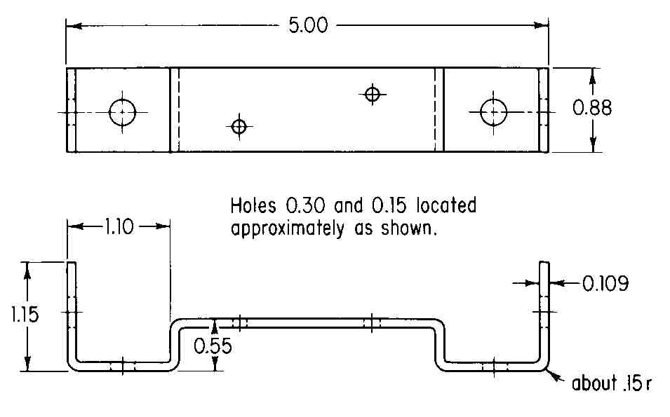
FIG. 50 (Prob. 21.) Front and top views of a bracket.
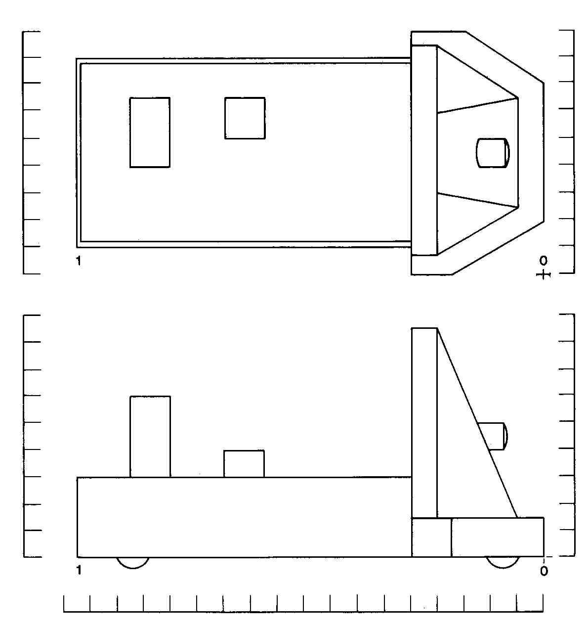
FIG. 51 (Prob. 22.) Front and top views of an automatic guided vehicle.
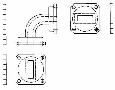
FIG. 52 (Prob. 23.) Three orthographic views of a waveguide bend or
elbow.
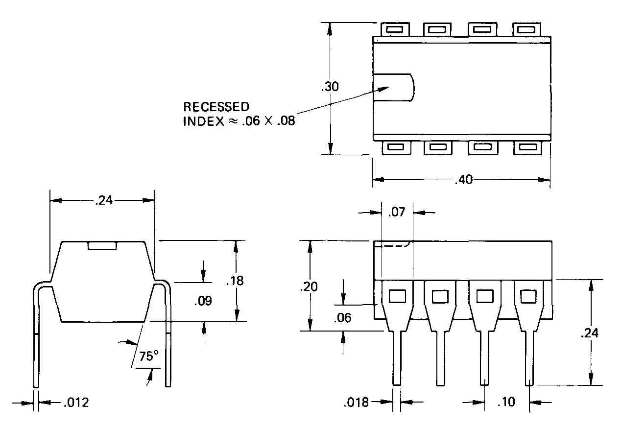
FIG. 53 (Prob. 24.) Three views of an 8-pin plastic package.
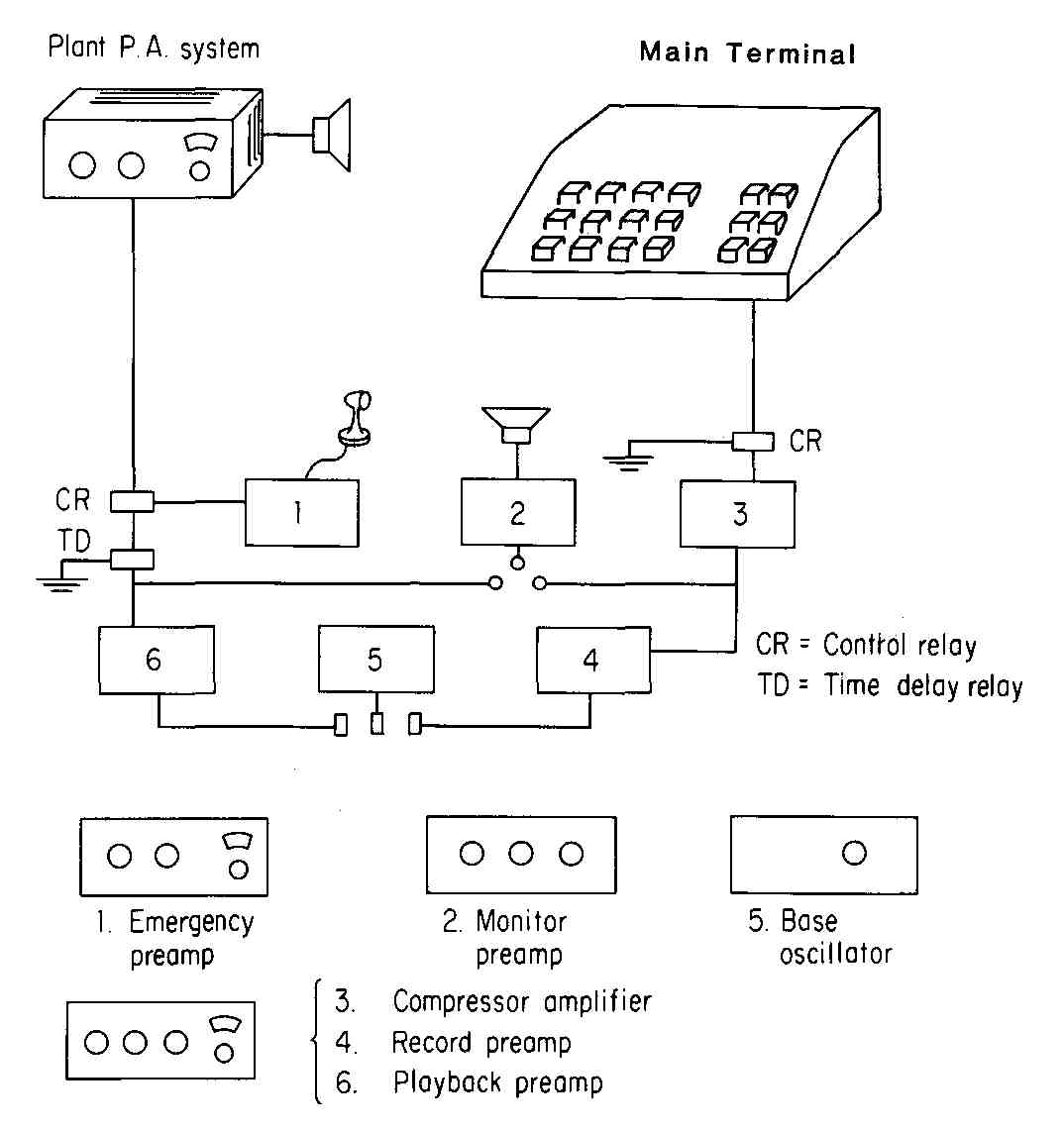
FIG. 54 (Prob. 27.) A partially completed pictorial diagram of an
automatic paging system.
27. Construct a complete pictorial drawing of the automatic paging system shown in FIG. 54. The front panel of each of the six blocks is shown in the figure. The rest of each unit can be shown as the plant public address (PA) system, upper left, appears. If oblique projection is used, the emergency preamplifier (block 1) will appear almost the same as the plant PA, upper left. Label each unit and the relays. Assume all items (1 through 6) are the same size. Use 11 X 17 or 12 X 18 paper.
28. Make a pictorial drawing of the personal or business computer system shown in FIG. 55. Add the plotter (shown at lower right) if your instructor so indicates. Maintain the relative size of the terminal, monitor, and peripherals, using the overall dimensions shown in the figure. Use 11 X 17 or 12 X 18 paper.
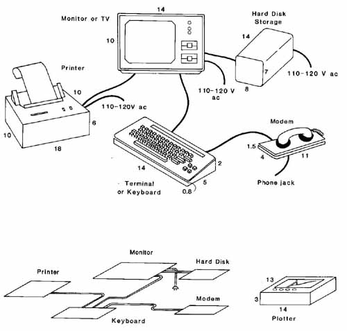
FIG. 55 (Prob. 28.) Elements of a personal computer system. Overall
height, width, and depth dimensions are shown except for depth of monitor.
A partial oblique pictorial is shown below.
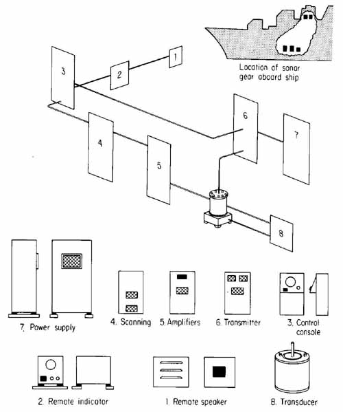
FIG. 56 (Prob. 29.) Elements of a sonar system and partial pictorial
layout.
29. Make a pictorial drawing of the sonar system shown in FIG. 56. Show each unit at the location shown in the partial pictorial diagram. Maintain the proportional sizes of the units. Use 11 X 17 or 12 X 18 paper.