AMAZON multi-meters discounts AMAZON oscilloscope discounts
1 Introduction
In recent years, there has been a steady evolution toward the use of solid-state components in industrial control. This does not mean that all electromechanical devices will be replaced, but they will share a smaller part of the industrial control spectrum in the future.
This section covers the drawings encountered in many different industrial control situations, from basic motor control to computer control. Almost all industrial control drawings follow some drawing standard or recommended practice, and these standards will also be described.
In general, as mentioned previously in the text, there are several types of drawing that will be associated with all types of control. They are: (1) the elementary diagram or schematic, (2) the wiring diagram, (3) the layout, (4) the block plan, (5) the parts list, and (6) the assembly drawings. However, some types of industrial control have associated specialized drawings, which will also be covered. An interesting phenomenon takes place in industrial control drawings; namely, as the control circuits become more sophisticated and complex, the drawings tend to become simpler. This will become obvious as the section proceeds.
A word of caution should be inserted here. Although this section presents industrial control drawings in discrete categories (e.g., electromechanical, solid-state logic, etc.), in reality, these types of control are sometimes used together. This can, in some instances, present nightmares to the drafter putting them down on paper. Basic concepts will show how to ease this interfacing chore.
2 Basic Motor Control
Most designers and drafters doing industrial control work start by “cutting their teeth” on some type of motor control circuit. Before delving into the types of drawing used in motor control circuit design, it is a good idea to first understand the functions of motor control and some of the components associated with motor controllers. There are certain definite functions that are performed or governed by motor control. These are: (1) starting, (2) stopping, (3) running, (4) speed regulation, and (5) protection. Starting technically refers to rotating the motor from zero speed to maximum (breakdown) torque speed. Running refers to propelling the motor from maximum torque speed to load speed (usually faster). These two functions are accomplished by one device in most motor control circuits. Speed regulation is done by some device such as a rheostat in a motor control circuit. Motor control circuits provide protection for both the power source and the motor. An example of one of the motor control functions is “reduced voltage starting,” which reduces the current inrush during the starting period of a motor or machine. This eliminates or minimizes the shock of a quick start on the driven machine, the reduction of voltage in the line or system to which the machine is connected, and the dropping out of synchronism of synchronous motors on the line. Reduced-voltage starters, which provide smooth accelerated starting without a serious drop in line voltage, are available.
A large motor in a New England plant requires 56s starting time under normal load. An oil-well pump in Texas will suffer serious damage if its rotor locks and the motor is not tripped from the line in 20s. A conveyor drive motor in a Florida potash plant can withstand 25 percent overload for 30 mm, but a compressor motor in Missouri may burn up in 3 mm at 25 percent overload. Each of these motors must be protected from abnormal overload currents, which creep in from time to time.
An electric motor controller is a device, or group of devices, which controls the electric power delivered to the motor. Motor controls range in complexity from a simple manual motor starter to an elaborate motor control center. Some basic control devices which may be built into motor controllers, as well as other industrial controls, are described in the following paragraphs.
A circuit breaker has the function of interrupting the flow of power in a circuit under normal and abnormal conditions. Although it might be used as a power (disconnect) switch, its primary function is to protect the line against abnormally high currents. Hence, it is designed for infrequent operation only. Just as frequently, a line switch and a set of fuses are used in place of a circuit breaker. The switch is used as the disconnect, while the fuses protect the line against faults.
A contactor is a device for repeatedly establishing and interrupting an electric power circuit. In essence, it is a specialized type of relay. Usually operated magnetically, it can be operated in line or can be remotely governed by pilot devices or relays. The overload relay is used to interrupt maximum over load current or to remove the power supply from a starter and motor under a normal overload. Pushbutton switches are used to energize or deenergize the motor controller, and thus start and stop the motor, respectively. Transformers are used to reduce the line (power-source) voltage to the control-circuit voltage. Sometimes, transformers are not used, but most designers prefer to have their control voltages at 120 V ac or less for safety reasons. Many motor controllers have indicating, or pilot, lights on them to show whether the motor is running or stopped.
The types of drawing encountered when doing motor control work are the elementary diagram, the wiring diagram, the layout, the motor-control-center layout, and the motor-control-center schedule. FIG. 1 shows two types of motor controller. FIG. 1 shows the elementary diagram of a motor controller. This diagram may appear a little strange to the reader because of the unusual symbols. Unusual symbols can appear because of two factors: (1) different devices are often used in industrial controls than in computer and communication equipment, and (2) different, or alternative, symbols are often used for components that are commonly used. A number of alternative symbols are used in diagrams of this type. These include the contacts and heaters. The unit shown in this diagram is a combination motor starter. Combination means that it contains both the motor starter and a power-source disconnect (switch). Usually in industrial control, combination motor starters are used.
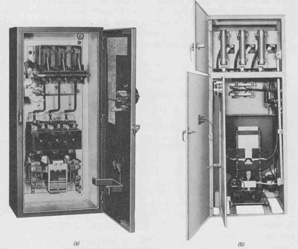
FIG. 1 Two types of motor controller: (a) switch-type combination starter;
(b) synchronous motor starter. (Allis-Chalmers Manufacturing Company.)
The motor control circuit in the elementary diagram is divided into two distinct circuits, the load circuit and the control circuit. The load circuit, which provides the utilization power to the motor, is drawn horizontally from left to right. The control circuit, which contains the operating coil of the contactor and provides the motor control, is drawn so that devices are arranged horizontally in vertical rows like a ladder. This drawing shows only the first “rung” of the ladder. This motor control circuit operates in the following manner. The disconnect switch (DISC) is closed and usually remains closed all the time unless it is necessary to disconnect the motor from the line circuit. With the disconnect switch closed, voltage is applied via the control power transformer to the control circuit. The start pushbutton (2PB) is depressed and energizes the contractor coil, and its power contacts apply lone voltage to the motor, which it starts and runs. In parallel with the start pushbutton is a contact, which is also on the motor starter, that keeps the contactor coil energized when the pushbutton is released—in other words, it “holds on” the contactor. The three overload relays (OLs, also called heaters) in the load circuit sense the amount of current going to the motor. The overload relays are temperature-sensitive devices. If the load current is too large or the circuit is overloaded, the temperature of sensitive coils becomes too hot, causing the temperature contacts in the control circuit to open up, and shutting down the motor. Because overload relays are tempera ture-actuated devices, care must be exercised in their selection, with attention to the temperature characteristics of both the relay and the motor.
There are many ways to control motor-starter contactors or relays. FIG. 3 shows seven typical methods of industrial control. If these methods were used to control the motor in FIG. 2, the devices— knife switch and pressure switch, for example — would appear in the control circuit. Circuits (a) through (e) are two-wire control. Circuits (f) and (g) are three-wire control, using a contact from some other device such as a relay for automatic control.
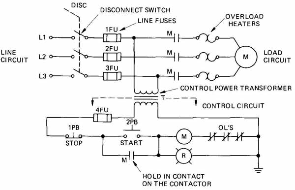
FIG. 2 Elementary diagram of a pushbutton motor control circuit.
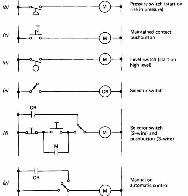
FIG. 3 Typical methods of industrial control: parts f and g represent
three-wire control; the others, two-wire control.
The wiring diagram in FIG. 4 shows exactly how the motor starter in FIG. 2 is wired. This type of diagram helps the electrician install and maintain the motor control circuitry. Most electrical-control manufacturers have booklets available containing many of the motor control wiring diagrams. These book lets are of invaluable aid to the designer-drafter in designing and laying out the motor control circuits.
Many times an engineering job will require that many motors be con trolled from a centralized location. In order to handle this requirement, a motor control center is a convenient, economical, versatile, and designable package that allows an engineer to put a multitude of different types of motor controller in one enclosure. It is a compact, floor-mounted assembly, comprised principally of combination starters. It consists of one or more vertical sections, with each section having a number of spaces for motor starters. The number of spaces is determined by the horsepower ratings of the individual starters. For example, a starter that will control a 10-hp motor will take up less room than a starter that will control a 100-hp motor. The motor control centers are built so that they will have starters on one side (front-of-board construction) or both sides (back-to-back construction). Basically, motor control centers have the main power busbar running horizontally and continuously through all sections and individual section busses running vertically. The motor starters plug into the section vertical busses. The drawings encountered in designing and specifying motor control centers, besides the elementary and wiring diagrams just discussed, are the motor control center layout, schedule, and single-line diagram.
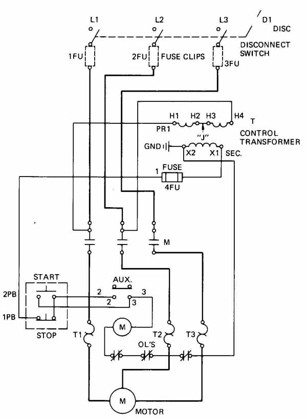
FIG. 4 Wiring diagram of a pushbutton motor control circuit.
FIG. 5 shows a typical motor control center (front-of-board construction) layout. This drawing is done to scale. Each section is numbered (1,2, etc.), and each space is lettered (A, B, etc.). If the motor control center were of back-to-back construction, two layouts would be required and an additional letter would appear in each section to designate front (F) or rear (R). The height of the space is determined by the size of the motor starter; the vertical section widths, heights, and depths are determined by the manufacturer, but are in accordance with National Electrical Manufacturers Association (NEMA) Standards. FIG. 6 shows the motor control center depicted in the layout of FIG. 5. Associated with the motor control layout is the motor control center schedule shown in FIG. 7. This schedule is developed by the designer to show the “nuts and bolts” of what types of motor controller go into the motor control center. The motor control center schedule usually appears on the same drawing as the layout. Along the left margin is listed the unit or space number, and adjacent to this number are all the particulars associated with the motor controller going in that space. For example, the motor controller going in space 1B is a combination motor starter (CMS), full-voltage (FV), nonreversing (NR), with 3 poles, a 30-A switch, 1.4-A fuses, 1 normally open contact-on contactor, a red “ON” pilot light, and a three-position selector switch for three-wire control (probably hand and thermostat). The controller is for a motorized steam unit heater.
The single-line diagram is a drawing which represents three-phase power and controls as a single line. It will be discussed at length in Section 10.
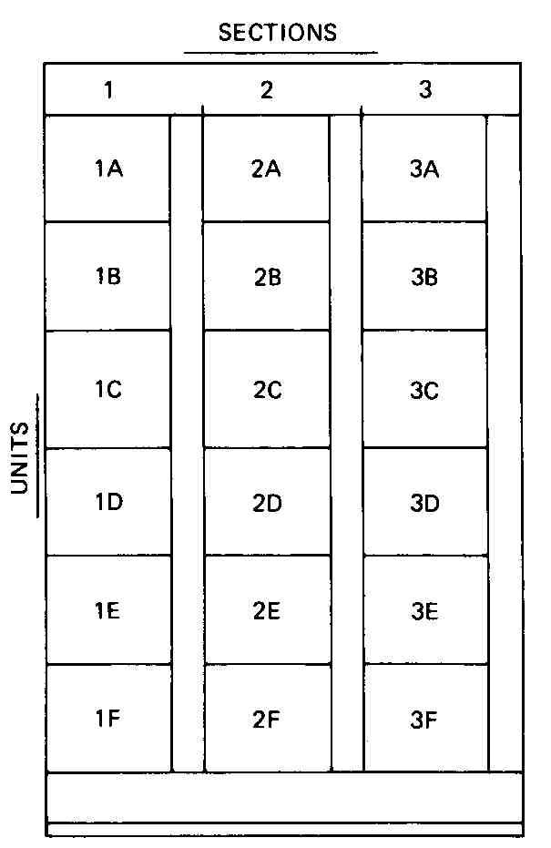
FIG. 5 Motor control center layout having three vertical sections.
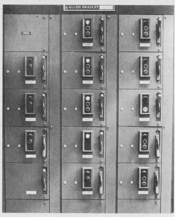
FIG. 6 Photograph of a motor control center.
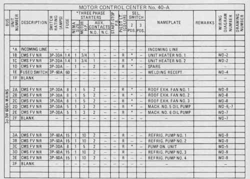
FIG. 7 Motor control center schedule.
3 Electromechanical Controls
Basically, an electromechanical control is a device that is electrically operated and has mechanical motion, such as a relay, servo, solenoid, etc. The motor starter contactors discussed in the previous section are electromechanical devices. Today, the majority of the devices used in industrial control are electro mechanical, although, as mentioned, a larger percentage of the devices are becoming solid-state. Builders and users of industrial equipment have long realized that the safety of the operator and the continuance of production are of primary importance in the design and purchase of such equipment. Good drawings help promulgate such equipment.
In electromechanical design, the standards for the drawings that are most widely accepted and most frequently encountered are the Joint Industrial Council (JIC) “Electrical Standards for Mass Production Equipment” (EMP-l-67) and “General Purpose Machine Tools” (EGP-l-67). Although these standards are strictly advisory and their use is entirely voluntary, they do provide an excellent and logical basis for industrial control drawings. These standards will be the basis for doing electromechanical industrial control drawings in this text. There are some slight differences in these standards, and they should be consulted before using them.
To begin with, the JIC standards describe the drawing’s size, the device designations and symbols to be used, the drawing arrangements, and the drawings required. The drawing’s size should be a multiple of 8+ X 11 or 9 X 12 in. with a maximum size of 24 X 36 in. Multiple drawings must be cross-referenced.
Device designations are shown in TABLE 1. Device designations cannot be used for other purposes. If special observations must be used, they should be listed on the diagrams. The device symbols are found in Appendix C. If no symbol is listed, then the prevailing symbol used in ANSI 32.E should be used. Logic symbols should be in accordance with NEMA Standard IC- 1.
The drawings for a complete industrial control job should include an elementary diagram, a block diagram, a logic diagram, a sequence of operations, a panel layout, an interconnection diagram, a stock list (bill of materials), an electrical layout, and a foundation drawing. Each one of these will be shown for the same piece of equipment in order to provide the reader with a sense of continuity and deeper understanding.
The elementary diagram, shown in FIG. 8, is the key to a set of industrial control drawings. The elementary diagram symbolically represents the control circuit and graphically shows the observer how the control system works. The elementary diagram is similar to the elementary diagram of the motor starter, with the source of power starting on the top left, is drawn horizontally, and connects the source circuit device [ disconnect switch, the contactor contact, and the overload coils (heaters)] and the loads (motors) at the top right. The control part of the diagram is drawn horizontally between two vertical lines, which represent the control power, from the source of the control power to the last control device required in the circuit. As can be seen, this method of drawing control circuits between two vertical control-power lines produces a diagram similar to a ladder; thus this is often called a “ladder” diagram. The control sequence starts on the top rung of the ladder and ends on the bottom rung, always going left to right.
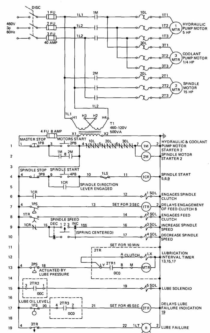
FIG 8 Elementary or ladder diagram. [ of Joint Industrial Council
(JIC).]
TABLE 1 Device Designations
Under selected control devices and on the right-hand side of the ladder diagram, there are terms describing the command and status functions, e.g., master stop. Associated with the right-hand-side control device and found under the descriptive terms and on the left-hand side of the ladder diagram are numbers called line numbers. They increase consecutively from top to bottom. Line numbers are used for reference: control devices are referenced to the circuits they control by these line numbers, in order to make it easier to under stand and follow the circuitry. The numbers between the devices are conductor (wire) numbers, and these numbers should not be repeated. Experience has shown the authors that minimum spacing should be - in. between lines and - in. between components and that minimum component size (circle diameter) should be - in., for clarity and ease of reading.
In order to draw an elementary diagram, a number of rules must be observed. Some of these rules are as follows. Actuating coils of control devices, i.e., relays, solenoids, etc., are to be shown at the right-hand side. All contacts should be shown between these coils— not necessarily on the same line — and the left vertical line. If subassemblies are used and their internal wiring diagrams are shown on separate drawings, the subassemblies should be represented on the elementary diagram as rectangles, with actuating coils or contacts shown. The control-device symbols are shown and numbered in the order in which the control sequence takes place. Services must be shown in the deenergized position, with the utilities (e.g., water to a flow switch) turned off and the equipment at its normal starting position. Only device contacts that are to be used should be shown. Contacts of multiple-contact devices should be on the line of the elementary diagram, where they are connected in a circuit, and all except contactors and control relays should be connected with dotted lines. Continuity of device descriptions should be maintained through all drawings required. Device functions should be shown adjacent to the respective device symbol.
Descriptive terms for command and status terms should be written in present or past tense. The values of electronic components, i.e., resistors, capacitors, etc., should be listed. If electronic diagrams are used, pertinent information for maintenance troubleshooting should be listed. Although quite a number of rules for elementary diagrams are presented here, do not become anxious or over-concerned. These rules are really just good common sense and will become “old hat” after you have done several elementary-diagram drawings.
Sometimes block diagrams are used to supplement elementary diagrams. when the complexity of the control systems warrants. On a block diagram, each block should be identified and cross-referenced in such a manner that circuitry can be easily located on the elementary diagram.
Logic diagrams are used in conjunction with the elementary diagram when static control or logic modules are provided. These diagrams will be discussed in detail in the next section of this section.
Associated with, and on the same drawing as, the elementary diagram is a verbal description, explaining how the circuit works. This description, called the sequence of operations, is shown in FIG. 9. Typing of the sequence of operations is preferred. Basically, the sequence of operations indicates the progression of operation of the devices shown on the elementary diagram and, thus, tells how the control circuit works. Graphical representations, such as bar charts, may be used to supplement the written description.
== ===
SEQUENCE OF OPERATION
A MACHINE OPERATION PRESS MOTORS START’ PUSHBUTTON ‘2PB” MOTORS START
B SELECT SPINDLE SPEED BY TURNING SELECTOR SWITCH “ISS” TO “INC’. ENERGIZING “3 SOL”, TO INCREASE OR TO ‘DEC’ ENERGIZING “4 SOL”, TO DECREASE SETTING.
C. WITH CORRECT SPINDLE DIRECTION SELECTED LIMIT SWITCH “ILS” IS ACTUATED. PRESS “SPINDLE START’’
PUSHBUTTON 4PB” ENERGIZING RELAY “ICR” WHICH ENERGIZES “1 SOL SPINDLE STARTS AND PRESSURE
SWITCH “IPS” IS ACTUATED “IPS” ENERGIZES “ITR” AND AFTER A TIME DELAY “2 SOL’’ IS ENERGIZED
PERMITTING MOVEMENT OF MACHINE ELEMENTS AT SELECTED FEED RATES
D PRESSING “SPINDLE STOP” PUSHBUTTON “3PB” STOPS SPINDLE AND FEEDS MOVEMENTS SIMULTANEOUSLY
LUBRICATION OPERATION
F PRESSURE SWITCH 2PS” IS CLOSED
1 TIMER “2TR” CLUTCH IS ENERGIZED WHEN MOTORS START
2 CONTACT “2TR I’ CLOSES AND ENERGIZES TIMER MOTOR ‘MTR” STARTING LUBE TIMING PERIOD
3 CONTACT “2TR3’ CLOSFS AND ENERGIZES TIMER “3TR”
G TIMER ‘2TR” TIMES OUT
1 CONTACT “2TR•l” OPENS, DEENERGIZING TIMER MOTOR “MTR’
2 CONTACT “2TR2” CLOSES, ENERGIZING “5 SQL”.
3 CONTACT ‘2TR 3’ DEENERGIZING TIMER ‘3TR”
4 LUBRICATION PRESSURE ACTUATES PRESSURE SWITCH “2PS”, DEENERGIZINC AND RESETTING TIMER ‘2TR’ CONTACTS ‘2TR I”, “2TR2” AND ‘2TR3’ OPEN.
CONTACT “2TR2” OPENING, DEENERGIZES “5 SQL”
H REOUCED LUBRICATION PRESSURE DEACTUATES PRESSURE SWITCH “2PS” AND SEQUENCE REPEATS.
SWITCH OPERATION
ILS 4” ACTUATED BY SPINDLE DIRECTION LEVER ENGAGED
IPS I1’ OPERATED WHEN SPINDLE CLUTCH ENGAGED
2PS ‘13, OPERATED BY NORMAL LUBE PRESSURE
IFS 161 OPERATED BY ADEQUATE LUBE SUPPLY
(above) FIG. 9 Sequence of operations. [ of Joint Industrial Council (JIC).]
== ==
The panel layout and interconnection diagram are shown in FIG. 10. These diagrams are of the same control system shown in the elementary diagram in FIG. 8. The panel layout shows the general physical arrangement of all devices inside the control-panel enclosure. The panel layout is used to tell the tradesperson how to layout and construct the control system. Devices are represented by squares, rectangles, and, sometimes, circles, and bear the same identification they had in the elementary diagram. Spare panel space is dimensioned. The panel layout also shows the layouts of the remote console or operator stations. These stations contain the switches that the operator uses to work the control system and are often called pushbutton stations.
The interconnection diagram, also shown in FIG. 11, shows all terminal boards and their associated identification within the electrical control system.
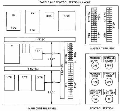
FIG. 10 Panel layout and interconnection diagram. [ of Joint Industrial
Council (JIC).]
Terminal-board numbers must correspond exactly to the number of the wire which attaches to the board.
The authors have seen several variations of the panel layouts that have been used successfully. One is to lay out each component on the panel, showing the coils, contacts, etc., of each device and the wire number associated with it. Another method is to show the interconnect wiring between the main control panel and the various operator stations. This method uses parts of a highway diagram and labels the wires’ numbers at the individual stations.
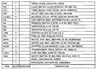
FIG. 11 Stock list or bill of materials.
The stock list, or bill of materials, shown in FIG. 11, tells what devices to use for the construction and maintenance of the control system. The stock list shows each device by designation, quantity, manufacturer’s name and model (and, sometimes, serial) number, and any other information necessary for construction and maintenance replacement. The stock list should appear on the same drawing as the elementary diagram or panel layout, but it may appear on a separate drawing because of its size. If it appears on the elementary diagram or panel layout, entries should be made from bottom to top to avoid running out of room. If it appears on a separate sheet, entries should be made from top to bottom, left to right.
The electrical layout, in FIG. 12, shows the outline of the equipment that the control system is to control. It shows the location of the main control panel, the operator’s console, and other remote-control devices, such as limit switches, whose location cannot be readily determined from the elementary diagram. Also shown are accessory units, such as hydraulic power units, which are not attached to the equipment, and their relative locations. All devices shown on the electrical layout have the same identification as they have on the elementary diagram.
4 Motors
Having discussed motor control and electromechanical controls, we should now discuss motors and how to draw them. Motors are available in all sizes and types from the tiny fractional horsepower motor found in the household refrigerator to extremely large motors (6000 hp and above) found on large pumps in electric power plants. Motors consume 35 percent of all the electric power generated in the United States. Because motors use this large percentage of energy consumed, many organizations from all facets of public life [Department of Energy, GSA, trade associations (NEMA), technical societies (IEEE, ASHRAE), and manufacturers] are considering ways to improve motor efficiency. There are over 340 companies producing motors and generators at approximately 450 different plants. Over 60 percent of the motors manufactured are used in equipment manufactured by industry while the remaining 40 percent are used by industry for “in-house” use.
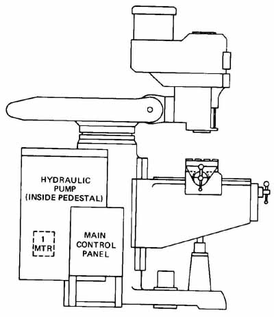
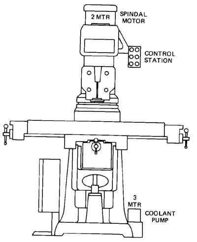
FIG. 12 Electrical layout.
FIG. 13 shows several types of motor, some of which are discussed in this section. Depending on which text is read, motor classification may differ slightly; however, in this text the following classifications are used: ac motors, dc motors, definite, and special-purpose motors. There are divisions or types in each of these classifications.
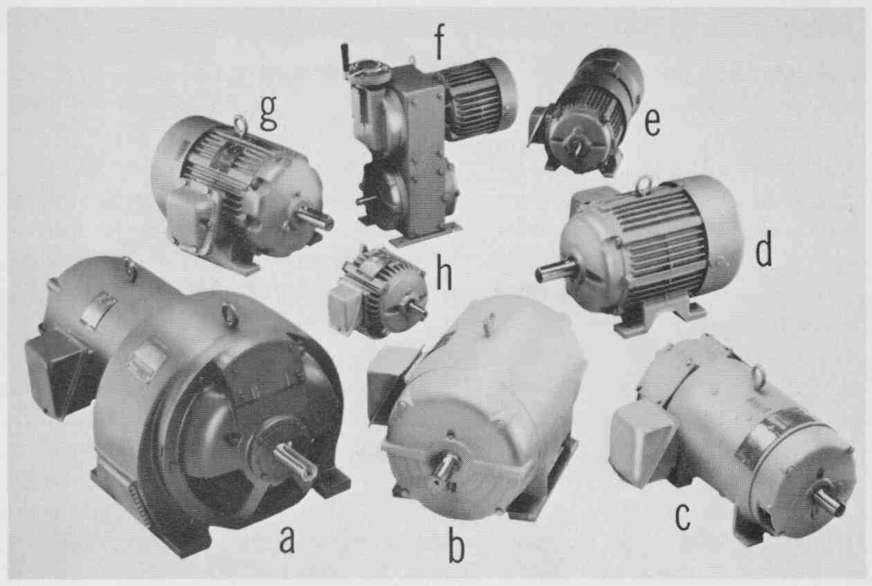
FIG. 13 Photograph of various types of motors: (a) eddy current clutch
motor; (b) squirrel-cage induction motor (drip-proof enclosed); (C) dc
motor; (d) squirrel- cage induction motor (totally enclosed—fan-cooled);
(e) brake motor; (f) mechanical variable-speed drive motor; (g) squirrel-cage
induction motor (explosion proof); (h) squirrel-cage induction motor
(totally enclosed, non-ventilated). (Louis-Allen.)
Alternating-current motors may be divided into three categories: synchronous, asynchronous, and single-phase motors. Synchronous motors are inherently constant speed because they operate in an exact synchronism with the line voltage frequency (in the United States, 60 Hz; in other parts of the world, 60 or 50 Hz). Therefore, a motor operating within line voltage frequency of 60 Hz could operate at a multiple of only 60, such as 540, 720, 960, 1200, 1800, and 3600 rpm. Synchronous motors are made in all sizes from sub-fractional, self- excited units to large horsepower (6000-hp +) dc-excited motors. Synchronous motors are used where a constant speed is mandatory or efficiency is required, power factor correction is required, or a combination of all these reasons. FIG. 14 shows the symbol for dc-excited synchronous motor and two types of asynchronous motors (squirrel cage rotor and wire wound rotor).
The asynchronous motor does not operate in exact synchronism with the line voltage frequency. The asynchronous motor is basically an ac transformer, with the line voltage applied to the primary (stator) and a voltage induced in the secondary (rotor). These motors are divided into two basic construction types: the squirrel-cage rotor and the wire-wound rotor. Wire-wound induction motors used to be the only induction motor that could have its speed varied, but with the advent of variable-frequency controls, speed can now be varied in the formerly constant-speed squirrel-cage induction motor. The squirrel-cage induction motor is the workhorse of industry and most common among the induction motors. FIG. 15 is a photograph of a horizontal squirrel-cage rotor induction motor driving a centrifugal pump. This motor and pump are part of a large air-conditioning system. The motor is rated at 60 hp with 460-V ac, 3-phase, 60-Hz line input and turns at 1770 rpm. This pump delivers 190 gallons per minute (gpm) of chilled water to large air-conditioning units.
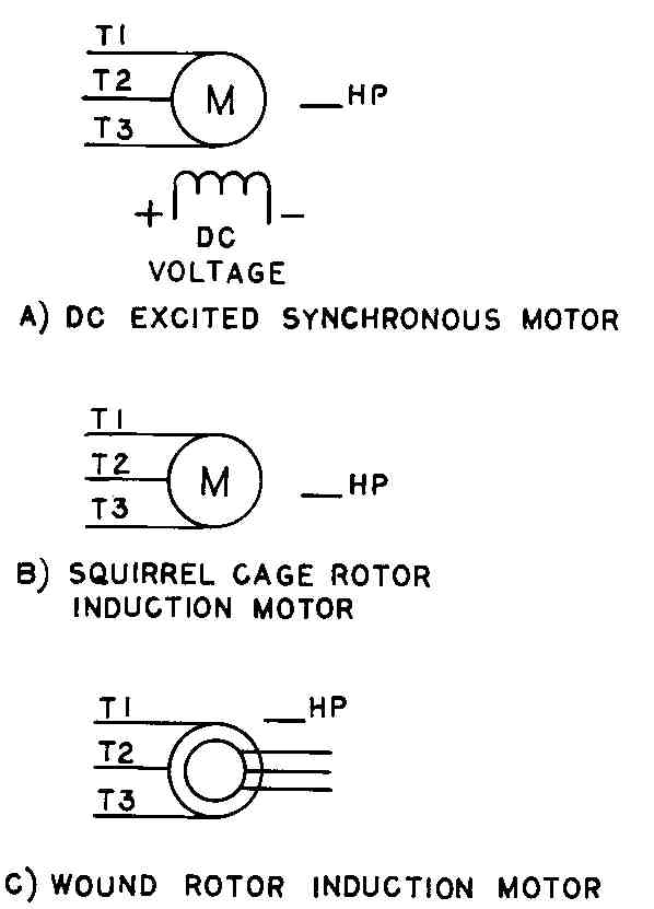
FIG. 14 Elementary diagram symbols of polyphase ac motors: (a) dc-excited
synchronous motor; (b) squirrel-cage rotor induction motor; (C) wire-wound
rotor induction motor.
There are numerous ways to draw induction motors depending on the type of drawing required. FIG. 14 shows the basic way to draw induction motors in an elementary diagram and a starter wiring diagram. The windings of many induction motors can be connected to two voltages or dual voltages. FIG. 16 shows the actual connection diagram of a 3-phase dual-voltage, wye-connected stator winding, induction motor that might be encountered by an electrician. For simplicity, the windings are often shown as straight line with labeling of only the connecting points. It is important to be able to draw motor winding connections, for this is how the motor is actually connected, and it might be necessary to communicate this information to an electrician.
Another drawing that an electrician might need is the motor outline or the motor end and side view. This information is needed for the physical installation of the motor, that is, the connection of the motor (driver) to the driven element (pump, fan, etc.), the mounting of the motor and driver element, and the checking of the necessary clearances and possible obstructions in the installation location. FIG. 17 shows the end and side views of a drip-proof induction motor.
The dimensions are given by letters which must be correlated to actual dimensions shown in the associated chart. This method of using a chart to give motor dimension is standard among motor manufacturers. In fact, the motor sizes for a given horsepower, speed, and enclosure are standard among motor manufacturers and are given a frame number to represent a standard size.
Single-phase ac motors receive the voltage a single-phase (e.g., 240- or 208-V ac) or line and neutral (120-V ac) power source. These are commonly called fractional-horsepower motors, although they are also available in the lower integral horsepower ratings. Generally, these motors are used for commercial and residential applications (furnaces, air conditioners, sump pumps, etc.) and are not found in large quantities in industry. FIG. 18 shows the schematic symbols for single-phase motors (general use and shaded pole) and the schematic of four commonly found single-phase motors, namely, the split phase, the capacitor start, the permanent split capacitor, and the shaded pole.
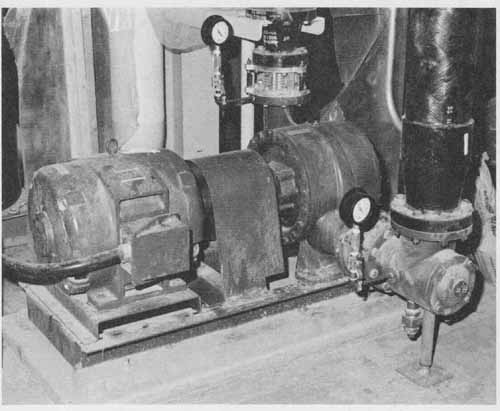
FIG. 15 Photograph of a 60-hp squirrel-cage rotor induction motor driving
a centrifugal pump.
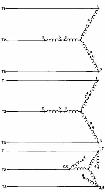
FIG. 16 Connection diagram of a three-phase, dual-voltage, wye-connected
motor: (a) not connected; (b) high-voltage-connected; (C) low-voltage-connected.
Direct-current motors are used in a wide variety of industrial applications because their speed-torque relationship can be varied over a large range, typically 8 to 1. Direct-current motors are applied where they can deliver three to five times their normal torque when starting. These motors have to be excited by either the same source voltage as the armature source voltage or separate excitation voltage; they are classified by the type of excitation of field they have. FIG. 19 shows the symbols for several types of dc motor.
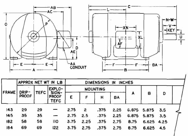
FIG. 17 Side and end views of a squirrel-cage rotor and the associated
dimension chart.
Definite and special-purpose motors are gearmotors, clutch and brake motors, torque motors, and timing motors. These motors are for special applications and are rarely encountered by drafters; therefore, they are not discussed in this text.
5 Programmable Controllers
In the previous edition of this text, there was a section on solid-state logic control which described various solid-state logic devices and PC boards and their application to industrial controls. Since that time, however, programmable controllers have essentially captured this market, forcing many manufacturers of industrial solid-state control to eliminate or minimize production of these devices.
The programmable controller is a programmable solid-state replacement for electromechanical “relay-type” controls or solid-state logic controls. Printed circuits were first manufactured in the late 1960s to meet the requirements of the automobile industry, which wanted to reduce the time and expense of building and testing new relay control panels between model years. Thus the programmable controller contains the relays in programmable logic; therefore, new control sequences require only reprogramming, and not modifying existing or building new relay control panels.
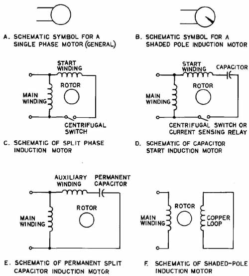
FIG. 18 Symbols for a single phase motor: (a) general use; (b) shaded
pole, and schematics of single-phase motors; (C) split phase; (d) capacitor
start; (e) permanent split capacitor; (f) shaded pole.
The heart of a programmable controller is the processor, usually a micro processor, but it could be keyboard-programmable solid-state logic or hard- wired solid-state logic. A typical programmable controller consists of four components—the processor, the power supply, the input-output (I/O) modules, and the program console. FIG. 20 is a block diagram that shows the arrangement of these components.
Programmable controllers used to have only digital input-outputs (I/O) or two I/O states (e.g., on-off, up-down, open-close, etc.), but today many programmable controllers have analog I/O or continuously varying I/O (e.g., temperature, pressure, 0 to 10 V dc, 4 to 20 mA, etc.). Today many programmable controllers can perform proportional, integral, and derivative (PID) control, operate on local-area networks (LANs) and interface with host computers. In fact, some programmable controllers rival small computers for certain applications.
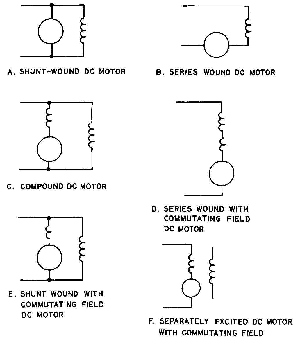
FIG. 19 The symbols for several types of dc motor: (a) shunt-wound dc
motor; (b) series-wound dc motor; (C) compound dc motor; (d) series-wound
with commutating field dc motor; (e) shunt-wound with commutating field
dc motor; (f) separately excited dc motor with commutating field.
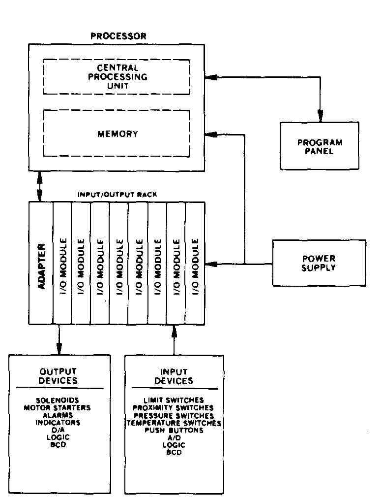
FIG. 20 Block diagram of a programmable controller. (Allen-Bradley Company.)
FIG. 21 shows a programmable controller mounted within an industrial control cabinet. The processor and power supply are mounted in the upper left. Below the processor-power supply are three rows of I/O. On each I/O row the top half is the I/O logic modules and on the bottom, the I/O terminals where I/O signals are received and transmitted. The I/O wiring is connected to these terminals and is routed through the wireway (running vertically along the left side) to the remote I/O devices.
Because the programmable controller replaces relay ladder-type logic, it is actually programmed in a relay ladder-type language. Many devices used for programming programmable controllers (CRT, keyboard panel) have relay symbols on the entry buttons. Some programmable controllers have the ability to be programmed in a Boolean-algebra-type language or other assembly-type languages. Many programmable controllers can be interfaced with a computer, and some have the ability to print out their stored “logic” in a ladder diagram. Presently, there are no drawing standards governing the use of programmable controllers in control work. The drawings associated with an industrial control job involving programmable controllers should include an “elementary,” a sequence of operations, a panel layout and interconnection diagram, a bill of materials, and an electrical layout. The drawings discussed in the previous sections will not be discussed in this section. Because the relays of a programmable controller are contained within the processor and are not discrete devices, there are varied opinions on what schematic-type or logic-type drawings are required for engineering, construction, and maintenance of the control system. Therefore, the authors will show a number of typical examples of the elementary diagram or logic diagram.
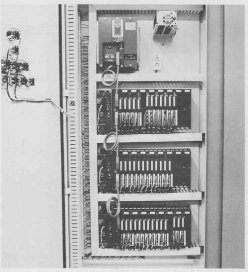
FIG. 21 Photograph of a programmable controller mounted within an industrial
cabinet. (Allen-Bradley Company.)
Figures 22, 23, and 24 show a method of drawing a programmable controller in an industrial control system. The system shown is the controls of Load Station B of a large shipping conveyor system in an industrial plant. Essentially, the Load Station B controls allow an operator to transfer cartons from conveyor A to conveyor B, load conveyor B, and transfer cartons from conveyor B to the main conveyor. All is done by controlling the motors of conveyors A and B and the raise solenoid of conveyor B. There are many interlocks to permit logical and safe operation and lockouts to permit testing the system. There is even a timer (1 TMR) to stop the system until a carton stops shimmying.
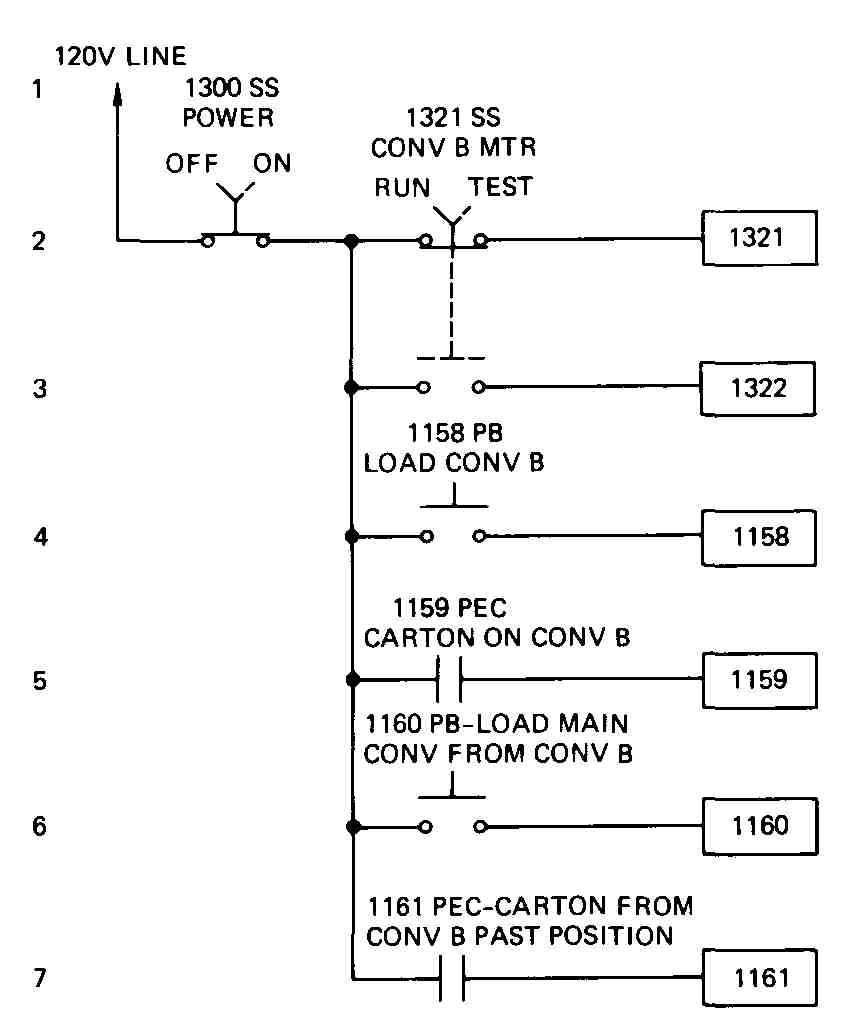
FIG. 22 Input diagram of a conveyor control system using a programmable
controller.
FIG. 22 is the input diagram showing the connections from the input device to the input modules of the programmable controller. This diagram is similar to a ladder diagram, but only one side of the power source is shown. Connections to external devices, such as photocells (e.g., 11 59PEC), are not shown, but their associated contacts that control a programmable controller input are shown. The inputs to the programmable controller are shown as rectangles and are identified with a four-digit number.
FIG. 23 is a relay-ladder logic representation of the internal programmable controller logic used. This is the logic used to program the programmable controller. The programmable controller “outputs” are shown as circles and are identified with a three-digit number. These outputs are either internal (400-series number), driving other internal relays, or external (100-series number), driving output devices, such as solenoids and motors. This logic diagram presents a couple of new twists in the standard relay-ladder diagram. For example, contact 492 on line 2 is actually connected to the left side of the ladder and is thus in parallel with contact 1158 on line 1.
FIG. 24 is the output diagram showing the connections from the output modules of the programmable controller to the output devices. Again, this diagram is similar to a ladder diagram, except that only the neutral of the power source is shown. The programmable controller logic of this system controls two devices, namely, the B conveyor motor and raise solenoid.
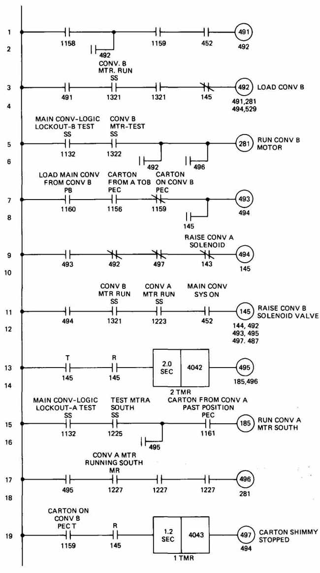
FIG. 23 Logic diagram of a conveyor system using a programmable controller.
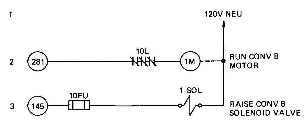
FIG. 24 Output diagram of a conveyor control system using a programmable
controller.