
The circuits on the following pages are an assortment, each of which can do useful things while teaching the reader more about the building blocks of electronics. Each contains one or more oscillators or amplifiers or a power supply, etc.
Learning about these and similar simple circuits and how to combine them will teach you how to build just about anything electronic. These projects provide an opportunity for you to be creative and combine circuits to make more complicated projects that will have a useful purpose. If you are a beginner at putting circuits together, it is suggested that you first read the article "Getting Started With Electronic Projects" in this issue, before you start any of these projects.
Then let your imagination take over and have fun
-------------
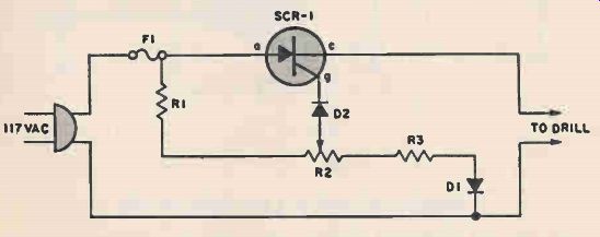
POWER TOOL TORQUE CONTROL
As the speed of an electric drill is decreased by loading its torque also drops. A compensating speed control like this one puts the oomph back into the motor.
When the drill slows down, a back voltage developed across the motor -in series with the SCR cathode and gate -decreases. The SCR gate voltage therefore increases relatively as the back voltage is reduced. The "extra" gate voltage causes the SCR to conduct over a larger angle and more current is driven into the drill, even as speed falls under load.
The only construction precaution is an extra heavy sink for the SCR. The SCR should be mounted in a 1/4-ifl. thick block of aluminum or copper at least 1-in. square; 2-in, if you drill for extended periods.
PARTS LIST FOR POWER TOOL TORQUE CONTROL
D1, D2-1A, 400 PIV silicon rectifier (Calectro K4-557 or equiv.)
F1--3-A"Slo-blo" fuse
R1-2500-ohm, 5-watt resistor
R2-250-ohm, 4-watt potentiometer
R3--33-ohm, 1/2 -watt resistor
SCR1--3-A, 200 PIV silicon controlled rectifier (Calectro K4-584)
-----------------
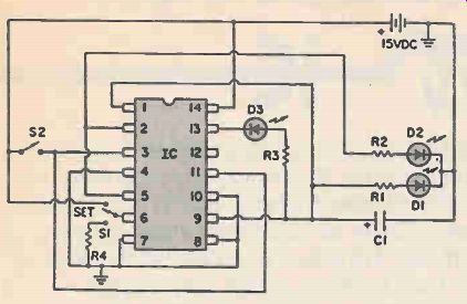
EYEBALL SPEED TESTER
PARTS LIST FOR EYEBALL SPEED TESTER
C1--1-uF electronic capacitor, 15VDC
D1-D2, D3-small LED
IC1--4013 dual flip-flop
R1, R2, R3-2,000-ohm resistor
R4-500.000-ohm resistor
S1-SPDT slide switch
S2-SPST momentary contact pushbutton switch
This circuit uses the two flip-flops of the CD 4013 integrated circuit to test your eyesight. Start by moving S1 from ground to "set" and back to ground. This will light D1 and D3. Now press S2. D1 and D3 will go off and D2 will go on, but D3 must go off slightly later than D3 due to built-in delays in the circuit. Can you see the difference in the two LED's? This makes a great experiment for kids to take to school.
--------------------
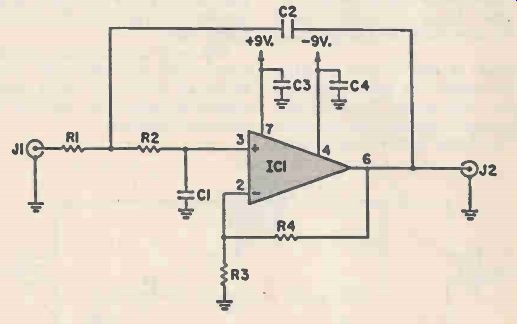
IC LOW-PASS FILTER
PARTS LIST FOR IC LOW PASS FILTER
C1, C2--0.01uF capacitor, 35 VDC
C3, C4-0.1-uF capacitors, 35 VDC
IC1-741 op amp
J1, J2,-phono jack
R1-12K-ohm resistor, 5%
R2-22K-ohm resistor, 5%
R3, R4-68K-ohm resistor, 5%
As its name suggests, a low-pass filter passes signals with frequencies lower than some specific value, called the cut-off frequency, but blocks passage of frequencies above the cut-off.
Illustrated here is an active low-pass filter having a 1000 Hz cut-off frequency. You can shift the cut-off by changing C1 and C2 together. To multiply the cut-off by a factor of N, multiply the capacitances of C1 and C2 by a factor of 1/N. For example, a 2000 Hz cut-off would require 0.005 uF capacitors while a 500 Hz cut-off calls for 0.02 uF capacitors for C1 and C2. Drive the filter directly from the output of a preceding op-amp stage for best results.
-----------------
WINDSHIELD WIPER MOTROL
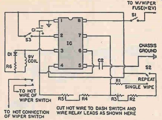
Ever have the problem of not being able to make your car wipers go slow enough? And sometimes, would you like to just press a button to make wipers flip one time? This circuit does both. Set S2 to the mode you want. If you pick "repeat", then R3 will determine the time between wipes (up to several minutes), so put R3 on a knob you can turn while sitting in the driver's seat. R5 will control the length of 'he wipe; you just set it once for your car. If S2 is set to "single wipe" then pressing S3 will kick the wipers up once. A very handy circuit.
PARTS LIST FOR WINDSHIELD WIPER CONTROL
C1--100-uF electrolytic capacitor, 15 VDC
C2 -0.1 uF capacitor, 15 VDC
D1 -1N4001 diode
IC1 -555 timer
R1--10 Megohm resistor
R2--20,000-ohm resistor
R3--500,000-ohm linear-taper potentiometer
R4- 18,000-ohm resistor
R5 -50,000-ohm linear taper potentiometer
R6-100-ohm resistor
S1 -SPST toggle switch
S2-SPDT toggle switch
S3--SPST momentary-contact pushbutton switch
RELAY--9 VDC coil with normally open
SPST switch contacts rated at 15 VDC/25 amps
---------------------
MAGIC TOUCH CONTROL
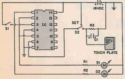
Ever wonder how a touch plate, like the kind you see on some elevator buttons, works? This circuit will give you a good feel for how the touch plate works in a circuit and lets you experiment further.
PARTS LIST FOR MAGIC TOUCH CONTROL
C1--4.7-uF electrolytic capacitor, 15 VDC
D1, D2-large LED
IC1--4011 quad NAND gate
R1, R2 R3--2,000-ohm resistor
S1--SPST momentary contact pushbutton switch
S2--SPDT slide switch
The plate can be just a small piece of metal or aluminum foil. Start by sliding S2 to "set" then back to R3. Now press S1. LED's D1 and D2 will flip. Now touch the plate to flip them back. The sensitivity of the touch plate will depend on humidity in the room and on R3 and C1 You can experiment with those in various ways.
------------------
TWIN WITCHES
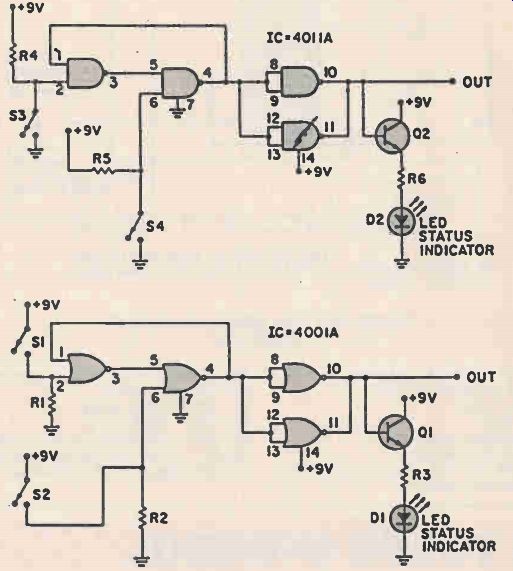
Two switches and a choice of logic gates make up this "bounceless" package. One switch turns "on;" the other turns "off" Either a 4001A NOR gate, r 4011A NAND gate set can be used, giving the constructor a choice of chips.
PARTS LIST FOR TWIN SWITCHES
D1, D2-small LED
IC1 -4001A quad NOR gate
IC2-4011A quad NAND gate
Q1, Q2-2N4401
R1, R2, R4, R5--1,000 to 4,700-ohm resistor
R3, 136-1,000-ohm resistor
S1, S2, S3, S4--SPST toggle switch
------------------------
TRANSISTOR CHECKER
PARTS LIST FOR TRANSISTOR CHECKER
B1-9 VDC battery
LED1, LED2-Light emitting diode
R1-1000-ohm resistor
R2--470-ohm resistor
S1-DPDT switch
S2--Momentary push button switch
S01--Transistor socket
It's pushbutton-easy to check transistors with this tiny marvel. Just plug the transistor in and push S2. If it's good and you set the PNP-NPN switch Si properly, the appropriate LED will light.
Don't know the type? That's okay. Plug it in and try both Si switch positions while you watch for the appropriate LED to light. You can even test diodes using the collector-emitter leads on the socket.
The collector-emitter leads can also be used to check continuity.
---------------------------
JOGGING PACESETTER
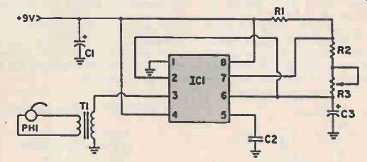
PARTS LIST FOR JOGGING PACESETTER
C1-100uF electrolytic capacitor, 16 VDC
C2-0.1-uF ceramic disc capacitor, 35 VDC
C3-1.0-uF tantalum electrolytic capacitor, 20VDC
IC1-555 timer
PH1-8-ohm miniature earphone
R1-10K, resistor R2-220K, resistor
R3-1-Megohm trimmer potentiometer
T1-miniature audio output transformer--1,000-ohm primary/8-ohm secondary
One of the problems faced by the beginning jogger, especially on city streets, is that of maintaining a constant pace. Tractor-trailer trucks, careening cars, and ill mannered dogs can all interrupt your concentration. While there is little that can be done about these nuisances, this little pacesetter may make them less severe. A miniature earphone in your ear driven by a 555 timer produces regularly spaced "ticks" just like a metronome. The pace can be adjusted via R3 from a leisurely one stride-per-second to a sole blistering six paces per second. The whole circuit complete with a 9-volt transistor radio battery weighs only a few ounces.
-----------------------
ECONOMY MICROPHONE
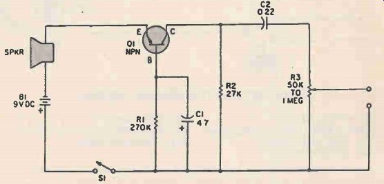
You can spend between six to ten dollars or more for a general-purpose microphone, but there's a better way, provided the mike doesn't have to be too small or portable. Pick up a junked (small) loudspeaker, four or five inches diameter is usually best (tiny speakers may have less sensitivity) and use it as a pickup device. Speakers and micro phones are both transducers. That is, they convert one form of energy (sound) into another (electricity) or vice-versa). This speaker, plus a few more general-purpose components is all you'll need to get a high-output microphone substitute. While not hi-fi quality by any stretch of the imagination the Speaker-Mic handles voice frequency signals very well.
Transistor Q1 can be just about any general purpose NPN with a Beta of about 50 to 150. The speaker can be anything you have lying around 01 virtually any impedance rating in the range of 3.2 to 16 ohms. If the entire circuit, including battery, is assembled in a small metal enclosure, you'll end up with a hand-sized "amplified microphone." The volume level is adjusted with potentiometer R3, which can be any audio taper unit from 50,000 ohms to 1-megohm. You can substitute a linear taper potentiometer if you have one lying around, but you'll find the adjustment range is scrunched together on one end of the shaft's rotation.
PARTS LIST FOR ECONOMY MICROPHONE
B1-9-volt transistor radio battery
C1-4.7 uF, 10-VDC electrolytic capacitor
C2-0.22-uF, 10 VDC capacitor
Q1-general purpose NPN transistor, see text
R1-270,000-ohm, 1/2-watt resistor
R2-27,000-ohm 1/2-watt resistor R3-potentiometer
S1-SPST switch
----------------------
PLANT MOISTURE METER
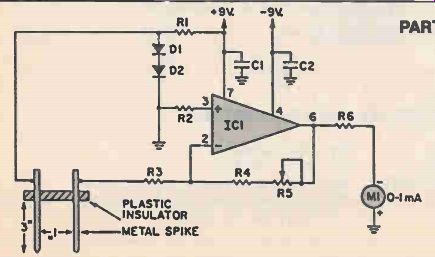
PARTS LIST FOR PLANT MOISTURE METER
C1, C2--0.01uF capacitor, 35 VDC
D1, D2--1N914 diode
IC1-741 op amp
M1-0-1 mA DC meter
R1-6800-ohm resistor, 10%
R2-15K-ohm resistor
R3-1000-ohm resistor
R4-10K-ohm resistor 1 mA
R5-100K potentiometer
R6-3300-ohms resistor
Talked to your houseplants recently? Well, if they could talk back, you'd hear plenty of complaints - most of them about water. Too much of the wet stuff is just as bad as too little. To assist you with the watering, try this little moisture meter.
Note that you will need to construct a probe assembly consisting of two metal spikes mounted in a wooden or plastic block. For the sake of uniformity, use the dimensions supplied. The spike can be nails or pieces of heavy wire (#8). Stick the probe assembly into the soil surrounding a just watered plant and adjust R5 for a deflection around mid-scale on M1. Thereafter you can use the meter to tell whether your plants are too wet or too dry.
Note that different plants are apt to prefer different degrees of wetness.
Also see: IC Testbench
More from EH magazine:
Adapted from: Electronics Handbook--Spring 1987