Integrated Circuits (ICs) are an electronic experimenter's dream come true. They have carried electronics light years ahead in just a few short years (since the Sixties) that they've been around. They make it possible to confine many complicated circuits and electronic functions into a tiny space, with very few additional (external) components.
That's why ICs are so important and it is why we present a special "project" section, just working with ICs (IC Testbench). By putting a few of these IC Testbench projects together, you'll learn much about the many varied and complicated jobs ICs can do and how to use them in today's sophisticated electronic devices and systems. The projects in this section are designed to provide some basic features that can be used in larger projects or by themselves as a learning guide.
--------------
IC LOGIC TESTER
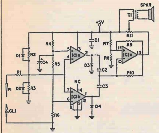
Here is the old familiar logic probe but with a new twist. Instead of displaying logic status with LEDs.
it does the job aurally. The logic-1 state, 2-volts or greater, is signaled by a high tone. On the other hand, a low tone sounds to indicate the logic-0 state, 0.8-volt or less. Inputs between 0.8 and 2 volts produce no output. (Note that this probe is designed especially for TTL and cannot be used for any other logic family.) The circuit requires a regulated 5-volt supply, which means that it can be powered by the same supply used by the TTL circuitry under test. Output can be taken from a miniature speaker, as shown in the schematic, or you may use a miniature earphone. Potentiometer R11 sets the output volume level.
PARTS LIST FOR IC LOGIC TESTER
C1 -0.1--uF capacitor, 35 VDC
C2-0.005--uF capacitor, 35 VDC
C3-0.1--uF capacitor, 35 VDC
C4-1.0-uF capacitor, 10 VDC
CL1--alligator clip
D1, D2-1N4001 diode
D3, D4-1N914 diode
IC1 -LM339 quad comparator
P1 -metal probe tip
R1 -10K-ohm resistor
R2, R3-220K-ohm resistor
R4-30K-ohm resistor, 5%
R5-12K-ohm resistor 5%
R6 -8200-ohm resistor, 5%
R7, Re, R10-56K-ohm resistor
R9-120K-ohm resistor
R11 - 1000-ohm audio-taper potentiometer
SPKR - miniature speaker
T1 -miniature audio output transformer (500 to 1000 ohm primary)
------------------
IC DIGITAL VOLTMETER
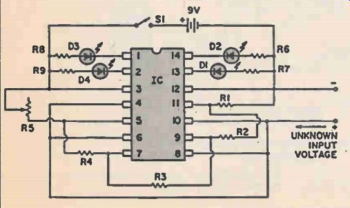
This circuit introduces the principle of a digital voltmeter and actually provides a very sensitive, high impedance meter for your workbench. The LM-339 is an IC containing four separate operational amplifiers of special type. These op amps compare the reference voltage set on one input pin with an unknown voltage on the other. If the unknown voltage exceeds the reference, the output goes high and lights an LED. D1 lights first.
With a slightly higher input voltage, D2 will light, etc. Variable resistor R5 allows you to set the voltage steps between D1, D2, D3 and D4 from about .02 volts per step to about 0.5 volts per step.
PARTS LIST FOR IC DIGITAL VOLTMETER
D1, D2, D3, D4--large LEDS
IC1--LM339 quad comparator
R1, R2, R3, R4--1,200-ohm resistor
R5-1 Megohm-ohm linear-taper potentiometer
R6, R7, R8, R9-470-ohm resistors
S1-SPST toggle switch
-------------
Automatic Lite Detector

When connected this system may be quick checked with a flashlight, while listening to the speaker and/or observing the op amp output on a scope. Modulating the light source mechanically with a pocket comb produces a buzzing tone, as the teeth of the comb alternately gate the light source.
A modulated LED can be used, with proper optical interfacing, as a communication source. The phototransistor is at its greatest sensitivity with the base lead open, though this may introduce unwanted hum. A 100K to 1 Meg resistor (R6) may be run to ground to check the best compromise.
PARTS LIST
C1, C2--10-uF electrolytic capacitor, 15VDC
C3--50-uF electrolytic capacitor, 25 VDC
IC1--741 op amp
Q1--FPT100 phototransistor
R1--47,000-ohm resistor
R2--1,000 to 10,000-ohm resistor
R3, R4--4,700-ohm resistor
R5--500,000-ohm resistor
R6--100,000 to 1 Megohm resistor (see text)
SPKR -PM speaker
T1 -audio output transformer 500 to 1000-ohm primary.
-------------------
SOLID STATE THERMOMETER
PARTS LIST FOR SOLID STATE THERMOMETER
C1--0.1-uF capacitor, 15 VDC
D1 through D6 -1N4148 diode
IC1--4009A hex buffer
R1--100,000-ohm linear-taper potentiometer
R2, R3--Megohm resistor
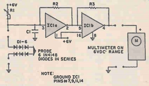
Here's a precision thermometer which uses low cost diodes. You could interface it with a frequency counter, or it can be read directly with a low-cost (20-thousand ohms-per-volt) volt-ohm-meter.
The thermometer's precision depends on the accuracy of the thermometer you use to calibrate it. If you're not sure, average several inexpensive units to get the nearest reading, throwing out all readings which are too far off (that's the way the manufacturers of low-cost thermometers do it.
The circuit uses a pair of 4009 inverter sections, biased into the linear region to amplify the temperature effects upon the diode probe. In this application, the adjustment potentiometer, R1, is set to give a mid-scale reading at room temperature on a typical multimeter set on the 6 volts DC scale.
If a separate 0-1 DC milliampere meter is available, it could be calibrated directly in degrees F or C, with a suitable resistance in series with the amplifier output.
Also see: Chip-by-Chip
Adapted from: Electronics Handbook--Spring 1987