By Homer L. Davidson
This unique little AM radio is low-cost and simple to build. In fact, you can put it together in a couple of evenings or less. The radio consists of only two inexpensive IC components that operate from two small AA batteries with loud speaker reception plus a handful of other parts. No outside antenna is needed to pick up your favorite stations. IC101 (ZN414) costs $2.00, while IC102 (LM386) costs less then one dollar.
IC101, the ZN414 looks physically like any ordinary transistor. However, inside its case is a 10-transistor, tuned radio frequency (TRF) circuit using Ferrante developed technology. The circuit includes a complete RF amplifier, a detector and an AGC system (automatic gain control) providing a high-quality AM tuner. No setup or critical alignment is required, except adjustment of R2. IC101 may be wired directly into the circuit without a transistor socket.
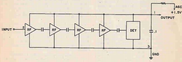
Figure 1. The ZN414 IC has the equivalent of a 10 transistor stage,
but it looks Just like an ordinary transistor.
-------------
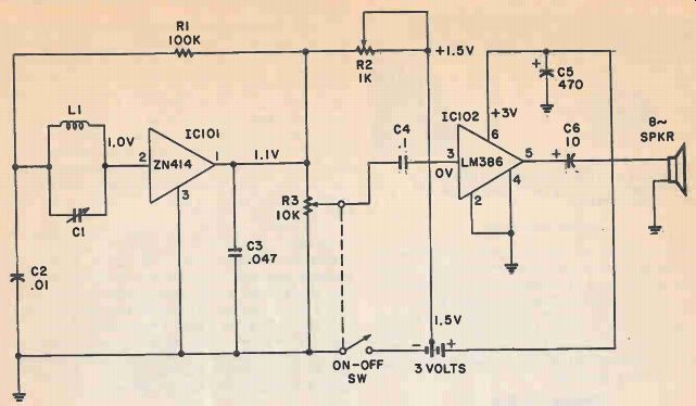
Figure 2. The actual circuit is shown with IC101 and IC102. Volume is sufficient to drive a small speaker.
PARTS LIST FOR TWO-IC RADIO
L1--72 Turns #24 or #30 enamel or 3 / 8x5" ferrite rod
C1--365uFD tuning capacitor
#AT-232 (Circuit Specialists) or #185-VA (ETCO)
C2--.01 100-VDC capacitor.
C3--.047 100-VDC capacitor
C4--.1 100-VDC capacitor
C5--470uFD electrolytic 35-VDC capacitor
C6--10 uFD electrolytic 35-VDC capacitor.
R1--100 K 1 / 2 watt resistor.
R2--Variable 1K thumb type resistor #32JC301 (Circuit Specialists)
R3-10K miniature vol. control with on/off switch, #31xP401 (Circuit Specialists)
IC1--ZN414 IC (Circuit Specialists)
IC2--LM386 IC (Circuit Specialists)
IC sockets--8-terminal type C8408 (Circuit Specialists)
Speaker--3 or 4-inch speaker
Battery holder-- #140 (Circuit Specialists)
Battery--2 required 1 1/2 V AA penlight cells.
Mics.--Plastic front panel, wood chassis, perfboard chassis, wood screws, solder, etc.
Addresses:
Circuit Specialists, Inc.
P.O. Box 3047 Scottsdale, AZ 85257
ETCO Electronics Corp.
North Country Shopping Center At. 9 North Plattsburg, NY 12901
Dick Smith Electronics
P.O. Box 2249 Redwood City, CA 94064-2249
Radio Shack stores, everywhere.
-------------
How It Works
To obtain good selectivity with a TRF (tuned radio frequency) circuit, IC101 must be fed with an efficient antenna coil and tuning capacitor. Select a 5 to 7 inch ferrite rod to wind the antenna coil upon. To pick up weak stations you'll rotate the receiver chassis. No additional antenna is needed for local radio reception. The tuned-in station is selected with Li and Cl. The RF signal is fed into input terminal 2 of 10101 (Fig 2). Here the tuned RF signal is amplified and detected providing a normal audio signal at output terminal 1.
Terminal 3 is at ground potential. The stator (stationary) Plates of C1 should be connected to the input terminal number 2 of 10101. Output terminal 1 is wired directly to the top side of the volume control R3.
Potentiometer R2 adjusts the AGO voltage supplied to input terminal 2 of 10101. Adjust R2 so that all stations come in nice and clear. If adjusted poorly you may have gurgling sounds with strong local stations. Improper adjustment of R2 may also cause the weak stations to disappear. So adjust R2 so all stations can be heard.
The audio signal applied to the volume control is controlled by R3. 04 (.1) capacitor couples the audio signal to pin 3 of 10102. R3 must be turned down for strong radio stations and turned full up with weak stations. 10102 amplifies the audio signal to drive a small speaker. Terminal 6 supplies the 3 volts which powers the audio amp. The speaker is coupled to terminal 5 with a 10 uFD electrolytic capacitor.
Terminals 2 and 4 of 10102 are grounded. A small 8 prong IC socket is used to plug in output IC LM386.
Do not plug in 10102 until the wiring is completed.
This small radio is powered with only two AA penlight batteries. A tap of 1.5 volts is fed to R2, supplying voltage to 10101. Both positive 1.5 and 3 volts are fed to the ICs. The radio is turned off or on with a switch on the back of the volume control R3, in the negative line of the small batteries.
Figure 3. Wind 72 turns of number 24 or 30 enameled wire on a 5-inch (or longer) ferrite rod.
L1 is cemented to the top plastic front panel with rubber silicone cement.
Locating The Parts
Any combination of L1 and C1 which covers the AM band may be used. C1 should be of the miniature type to keep the cost down. L1 may be a commercial tuned coil or can be constructed as described later.
IC101 and IC102 may be purchased from Circuit Specialists or Dick Smith Electronics. You should have no problem locating the required parts for this radio. The addresses of electronic mail order houses are given in the parts list.
Winding The Coil
Select a 3/8 diameter ferrite rod at least 5 inches in length. You will see these rods advertised in radio part stores, in grab-bag bargains or it may be purchased individually. If the rod is longer, it will provide better station pickup. L1 is mounted at the top of the plastic front panel with clear silicone cement.
Wind coil L1 close-wound with 72 turns of number 24 enameled wire (Fig. 3). Place a layer of scotch or masking tape at one end holding the wire tight against the ferrite rod. Let the spool of wire rotate around the leg of a chair or vise to keep the wire tight. Tape down the last few turns to keep the connecting wire from coming loose. You may want to put a drop of airplane silicone, or rubber cement on the end turns to hold them in place; then remove the tape. Leave about 6 inches of extra coil wire to connect to variable capacitor C1. Scrape off the enameled wire and tin with solder before soldering to the capacitor terminals.
The antenna coil is wound with number 24 or 30 wire-wrap wire. Besides winding coil Li this wire may be used as hookup wire. Since this wrapping wire is covered with a coat of plastic, it may be close wound directly on the ferrite iron core. The plastic covering must be removed from each end for soldering. Scrape off with a pocket knife or burn back the insulation with the soldering iron tip.
Preparing The Chassis
All components except the variable capacitor, volume control, antenna coil, speaker and batteries, are mounted upon a 2x3-inch perfboard chassis. Cut the small chassis from a larger piece of perfboard found at any electronic store. The very small holes allow mounting the IC socket and all parts leads through the perfboard. Solder each small component as it is mounted. Mark terminal 1 of IC 102 on the bottom side of board.
Keep the input and output components connected to IC102 apart.
In other words, keep C4 and C6 on opposite sides of IC102. Place large filter capacitor C5 on the same side as C6 (Fig. 5). The speaker leads from C6 will extend outward from the same side. No shielding of the input wires is needed. By keeping the input and output parts away from each other we prevent feedback (howling noise). Keep all wires as short as possible.
The front panel is made of a white piece of plastic 5x8 inches. The speaker hole is drilled out with small drill holes or with a circle cutter. If the round hole is cut out, place grille cloth or metal screen over the hole speaker protection, or drill out holes in the front panel, as shown in Fig 6.
Cut a piece of white pine board 7 1 / 2 x4 inches. No holes need be drilled in the back chassis except to mount the battery holder. The battery holder and perfboard chassis shown here were cemented to the rear chassis with a dab of clear silicone cement.
The small speaker is cemented to the front panel with silicone cement. Bolt the variable capacitor in place. If the small mounting screws of the capacitor will not mount level on the front panel, drill holes part way so the capacitor lies flat against it. Secure the volume control in the bottom 3/8 inch hole.
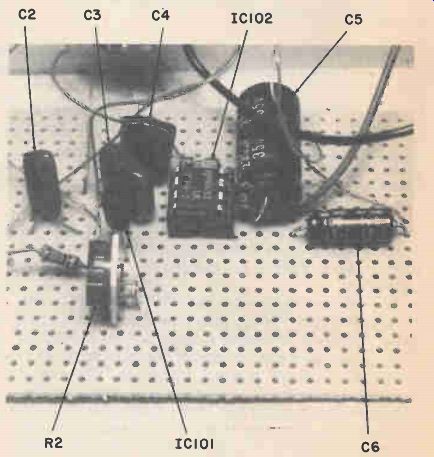
Figure 4. The input and output parts are mounted on separate sides
of IC102 to prevent feedback.
Mount the parts as they are wired into the circuit.
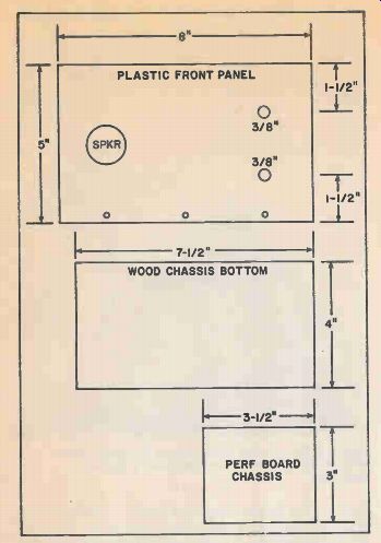
Figure 5. Here are the dimensions of the plastic front panel and rear
chassis. Cut a smaller parts chassis from a larger piece of perfboard.
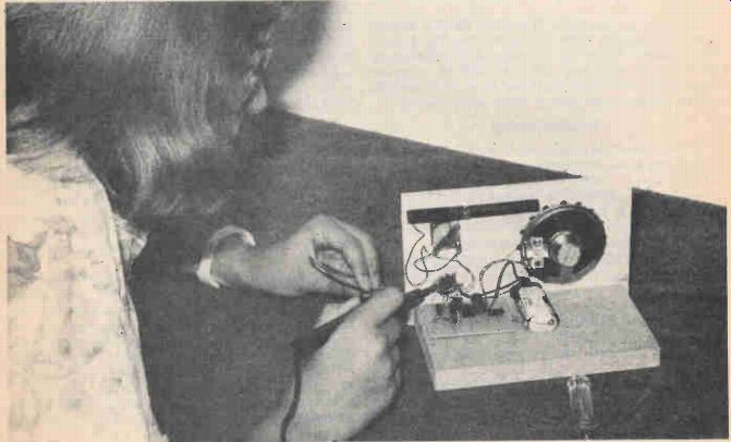
Figure 6. Solder and connect all wires from the small perfboard chassis
to those parts on the front panel. Double check each connecting wire.
Mounting and Wiring Components
Start at C6 and solder its positive terminal to terminal 5 of IC102. Slip the negative wire in through a hole close to the edge of the perfboard for connecting the speaker. Connect an 8-inch piece of hookup wire to pin 6 and the positive terminal of C5. The negative terminal of C5 solders to ground terminals 2 &4. Now, solder one lead of C4 to terminal 3, opposite the output components. Connect a four-inch piece of hookup wire to the other terminal of C4, which goes to the center terminal of the volume control (Fig. 6)
Next, mount IC101 through the holes and ground terminal 3. Connect C3 to terminal 1 and ground.
Mount R2 and connect it in series with R1. R1 and one end of C2 are tied to the rotor plates of the variable capacitor. There are several hookup wires that must be soldered to other parts and connected to those on the front panel and the wood chassis.
Connect a wire from C4 to the center terminal of the volume control, and the other (outside) terminals after the panel parts are mounted. Solder a piece of hookup wire from R2 to the 1.5 voltage source.
Another wire must be soldered from the top of the volume control to pin 1 of 10101. Connect a four-inch hookup wire from pin 2 of 10101 to the tuning capacitor. Solder both leads of L1 across the variable capacitor terminals. Last, but not least, solder the speaker and battery-connecting wires.
Connect a wire from the negative battery terminal to one side of the on/off switch. Solder the other switch terminal to ground. Tap the battery source at 1 1/2 volts and run the wire to one side of R2. This supplies voltage to 10101 through R2. The 3-volt positive battery lead is wired directly to pin 6 of LM386 and C5.
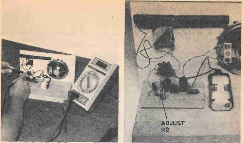
Figure 7. Take critical voltage measurements with a VOM or digital
multimeter (DDM). Compare the voltage measurements with the schematic.
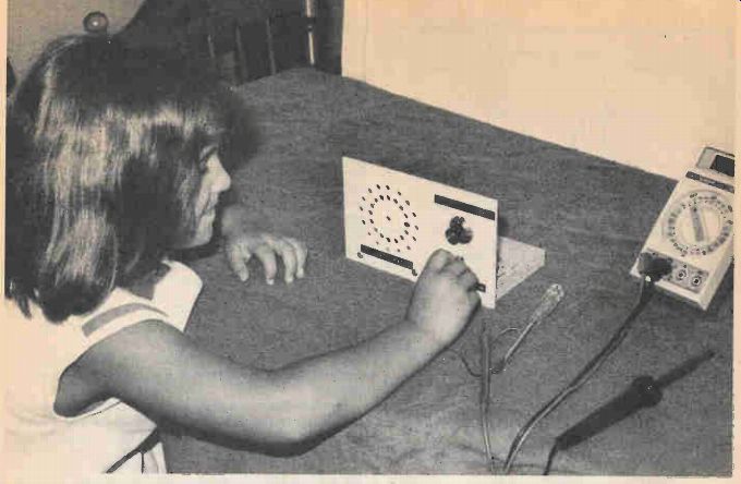
Figure 8. Here is the back view of the radio when completed. Adjust R2 for best overall station response.
Testing
Before turning on the switch, double check all wiring. Go from each part to each connection and make sure all parts are on the right wires. Check off each part on the schematic. Make sure each connection has a good soldered joint. Extreme care should be used when soldering IC101 (ZN414). Do not leave the soldering iron on too long. Use a pair of long nose pliers as a heat sink on each IC terminal.
Remember that IC101 has terminals like a transistor and is soldered directly into the circuit. Check all socket contacts of IC102 to be sure they are not shorted.
Now turn on the switch and rotate the dial to your favorite broadcast station. If by chance the radio is dead, recheck the wiring. The volume of local stations will not blast your ears, but is enough for personal enjoyment. You will be surprised how many stations can be received with only a 3-volt power supply.
Troubleshooting Go over all wiring and check for misplaced or poor connecting wires, if the radio us dead. Shut the radio off and take a meter reading across the switch contacts on the 20 milliamp scale of a VOM. This little receiver pulls a little over 5 mils of current. If the current measurement is above 10 mils, suspect a leaky output IC102, or inproper wiring.
Next, take voltage measurements on IC101 and IC102. Be careful not to short out the IC terminals (Fig.8). It's best to take voltage measurements at connecting parts. Measure the battery total voltage at pin 6 (3V). Pin 5 should be 1.6 volts. Proceed to IC101 if the 'voltages are normal on the output IC. Pins 1 &2 should be about the same voltage (1.1) if the IC is normal.
Another way to check the output IC is with a click test. Take a test probe or screw driver and touch the center terminal of the volume control. When normal a faint click will be heard in the speaker. If in doubt, remove the center lead and hold it between your fingers. You should hear a hum, indicating the audio section is normal. A loud hum or click indicates the trouble may be in the IC101 circuit.
Sometimes a connecting wire will break off after connecting other components. Take another peek.
Advance R2 and when it approaches R1, should hear a squeal or whistling noise if IC101 is normal. With R2 all the way down, you should hear local broadcast stations loud and clear. R2 is adjusted to pick up weak stations (Fig 9.). Besides adjusting R2, turning the radio chassis may help bring in weak stations, since the ferrite antenna coil is directional.
Conclusion
Dress up the front panel with stick-on labels or pressed-on letters. Be careful when soldering IC101 into the circuit. Check each terminal of IC101 from the bottom. Mark terminal 1 on the bottom side of the perfboard with a red or black dot for reference.
Double check the batteries for correct polarity.
Hooking the batteries up backwards may destroy both ICs.
Go over the wiring at least twice before firing up the radio. Install IC102 in the socket just before connecting the batteries. If you want to feel safe, insert the milliampere meter in series with the negative lead as power is applied. You may assume the output IC is hooked up correctly if the current is around 5 or 6 mils. Remove the meter probe at once if the current is extremely high. You may save the IC, with this current meter test. If the small radio sounds off the first time, pat yourself on the back or give out a loud yell for a job well done.
Also see: Build a TV Lite Pen
More from EH magazine: Tandy's Radio Shack
Adapted from: Electronics Handbook--Spring 1987