AMAZON multi-meters discounts AMAZON oscilloscope discounts
After studying this Section, you will be able to:
- List the standard drawing sizes.
- Explain the need for drawing quality.
- Identify some basic drafting tools.
- Explain the requirements for lettering.
- List the uses for the different line widths.
- Create an orthographic drawing.
- List basic parts of the computer hardware system.
- Define computer aided design (CAD).
- List some advantages of CAD.
The electronic drafting field requires high quality work. Drawings created by drafters will be used by others who will spend hours reading them. With the amount of time spent reading drawings, it makes sense to spend an extra few minutes making them easier to read. These readers may be your customers. Quality drawings are a good advertisement for a company’s technical ability.
DRAWING STANDARDS
This Section will cover the general drafting practices of industry. These practices will be based on the latest standards. Most companies closely follow military and industrial standards. The first standard you will study is that for lettering.
FREEHAND LETTERING
The name “freehand” does not mean without using templates. Some aids are used to set up horizontal guidelines.
The standard lettering style used in companies making electro-mechanical equipment is the single stroke upper case (capitals) gothic, FIG. 1. Most companies prefer this lettering to be vertical. The normal height of the letters will be 5/32 in. The reason for this style and height of lettering is to allow consistent microfilming. MICROFILMING is the process of photographically reducing the size of the drawings for documentation, storage, and fast retrieval. A microfilm of a drawing is retrieved and a “blow-back” made to get an original size drawing or blueline print.
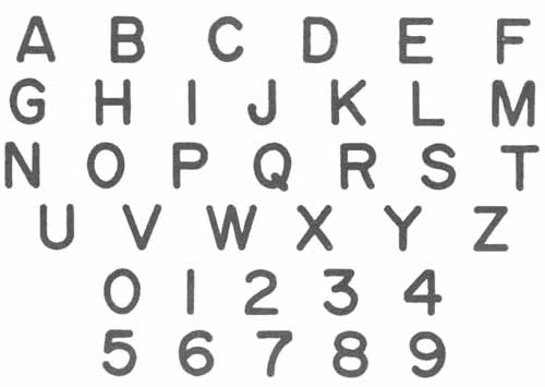
FIG. 1. Typical upper case lettering style.
Lower case lettering may be used for special applications. Some of the applications will be: connector pin identification, name plates, and switch positions. See FIG. 2 for single stroke lower case lettering.

Fig. 2. Typical lower case lettering style.
Some companies will permit you to use inclined lettering. If inclined lettering is used, it should have a uniform slant. The slant is normally 68 degrees, FIG. 3.
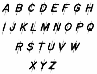
FIG. 3. Typical slanted lettering style.
Freehand lettering is used in most industries. You need to practice lettering until you develop good techniques. Get a feel for lettering composition. Composition is how the lettering looks in words and sentences. Use guidelines for freehand lettering, FIG. 4. One aid called an Ames lettering guide is popular. Guidelines should be drawn lightly so they are just visible at arms length.
MECHANICAL LETTERING AND TRANSFER LETTERING
When it is important to create a high quality drawing, mechanical lettering is sometimes used. One of the following three methods may be used:
1. Mechanical lettering is produced by using a scriber in a template, FIG. 5. With this tool, you can also create standard symbols and electronic symbols.
2. Typewriters may also be used to do lettering on drawings. You may also type on a transparent tape with an adhesive back. After the information has been typed, the tape can be cut apart and placed on the drawing.
3. Rub-on lettering comes on sheets in many styles. To put the lettering on the drawing, all you need is a dull pencil, ball-point pen, or similar tool. Position the letters or symbols on the drawing and rub over them to transfer them to the drawing, FIG. 6.
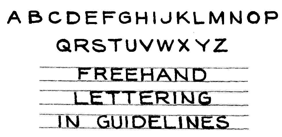
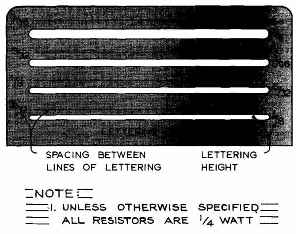
FIG. 4. A—Good freehand printing showing style and composition. B—Template
for setting up lettering heights.
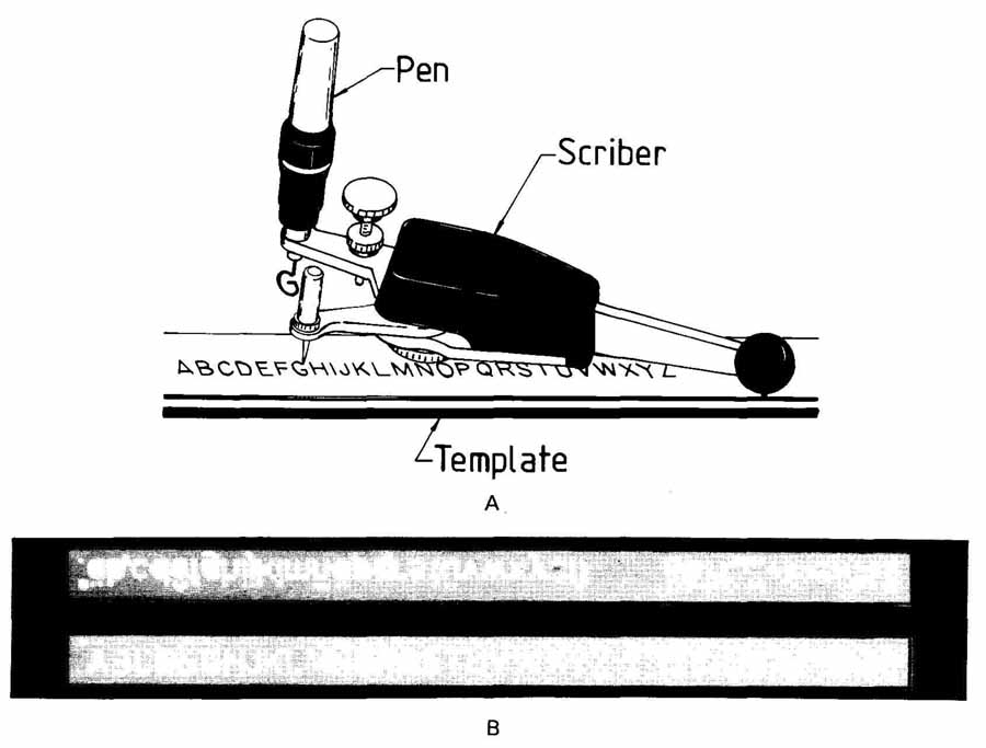
FIG. 5. A—Mechanical letters using a template and scribe. B—The template
that guides the scribe. (Staedtler Mars)
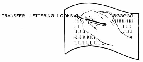
FIG. 6. Transferring lettering by rubbing them onto drawing.
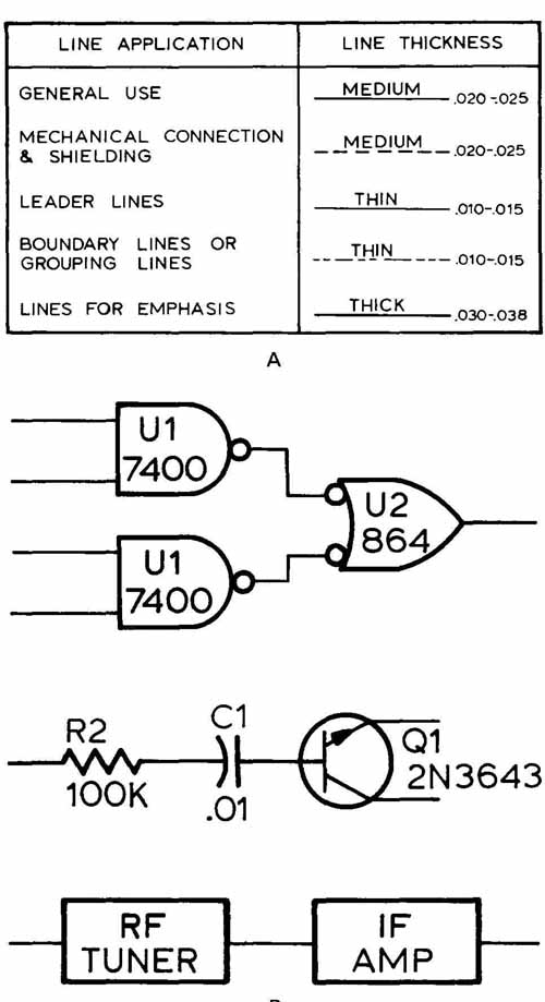
FIG. 7. A—Each type of line has a purpose in an electrical diagram.
B—Often part symbols are emphasized with heavy line width.
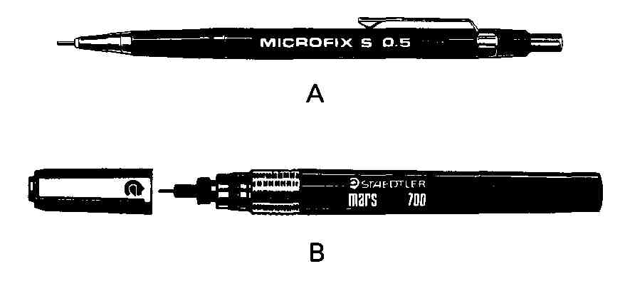
FIG. 8. These tools are used to create different and consistent line
widths. A—Thin lead pencils. B—Technical pens. (Staedtler Mars)
LINEWORK
All lines that we wish to reproduce need to be dark (dense). Electronic drawings require linework to be dark and about .02 in. wide. To make dense lines of consistent width requires practice. Different line widths will help accentuate features on the drawing, FIG. 7.
Refer to FIG. 8. Inked drawings make it easy to get different widths of lines You simply choose a different sized technical pen. Pencil drawings are more difficult. But with practice, in sharpening, rolling the lead holder as the line is drawn, and holding it against the straight edge, you will learn to get quality pencil lines. Thin lead pencils are becoming more popular in industry. They make it easy to create consistent linework.
EQUIPMENT AND MEDIA
Electronics drafting requires many of the instruments used by drafters in other fields. The major difference is the group of templates used. All drafters need to know how to purchase, use, and maintain their drafting equipment. To purchase drafting tools, you may want to go to an engineering supply store that carries professional brands. When you purchase the tools, the salesperson will be able to explain the use and care of each item. Care will normally mean keeping the tools clean with mild soap and water.
TEMPLATES
As an electronics drafter you will draw the same symbol repeatedly. This repetition will require the use of templates, FIG. 9. Templates are designed to be used with either pencils or technical pens. Templates designed for pencil work will have wider guiding slots to allow for the wider pencil lead.
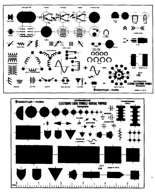
FIG. 9. Templates provide uniform symbols on electronics drawings.
(Staedtler Mars)
Technical pens used in the pencil templates will create sloppy symbols. Both technical pens and thin lead pencils can be used in pen templates.
When purchasing a template, consider specification standards on how symbols are constructed. Good templates will meet military and industry requirements. Most companies purchase templates for their drafters to use. They do this so that each drafter will be able to work uniformly in their system.
TAPES
Tapes are used in many ways in electronics drafting. They can be applied to graphs, diagrams, schematics, and printed circuitry. The tapes come in many different widths, colors, and styles.
DRAFTING TABLES AND MACHINES
Engineering firms are concerned that drafters have a good environment in which to work. A good environment will increase the drafter’s productivity. Most companies will supply all the drafter’s needs except for some of the small items. See FIG. 10 for a view of a typical drafting station.
DRAFTING KIT
Many drafting supply companies will supply the most common drafting items in a kit. Buying a drafting kit will normally save money. A typical kit will have the items shown in FIG. 11.
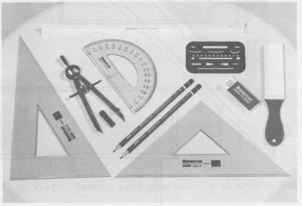
FIG. 11. A standard drafting kit. (Keuffel & Esser Co.)
DRAWING FORMATS
FIG. 10. Typical drafting table or machine is tilted for easy work.
Drawings created in industry must be done on standard sheet sizes. These sizes will be referred to by letter designation, FIG. 12. The reasons for keeping all of our documents on standard sized paper are:
1. Drawers and file cabinets are designed around standard sheet sizes.
2. They will fit or fold into a standard book form.
3. They will be the size of standard reproduction paper.
4. The sizes are readily available from suppliers. Format sizes larger than “F” are designated “J” and will be drawn on rolled stock. The maximum recommended length of a roll drawing is 144 in. (1 2 ft.).
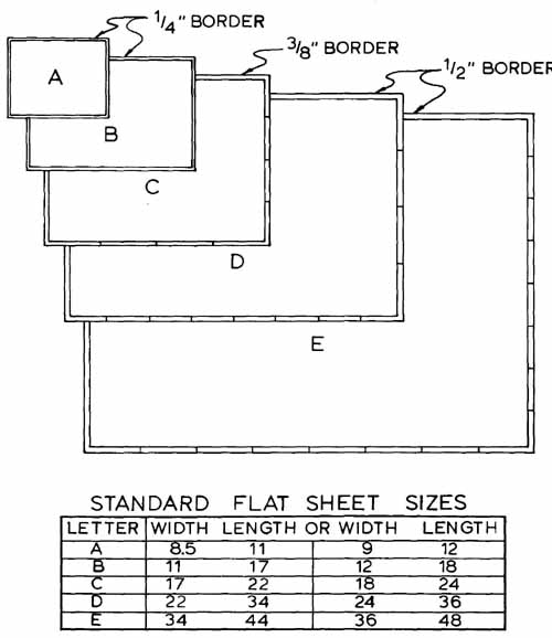
FIG. 12. Standard drawing format sizes. Allow for margins plus some
extra.
BASIC DRAFTING TECHNIQUES
In order to do a drafting task in a realistic length of time, you must understand some principles. This section will cover some needed drafting techniques.
GEOMETRIC CONSTRUCTION
Geometric construction is a graphical solution to a mathematical problem. The principles of geometry are applied often in engineering. To solve geometric problems, you will normally use a straightedge, triangles, compass, scales, and french curve. Below are some common problems worked for you:
1. Draw parallel lines using a triangle and a straightedge, FIG. 13.
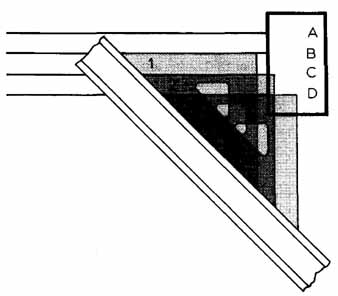
FIG. 13. Drawing lines parallel to line A and B.
Sample Problem: Add lines C and D.
a. Keeping the triangle firmly against the base straightedge, align its edge to B.
b. Slide the triangle to C and draw the parallel line.
c. Slide the triangle to D and draw the parallel line.
2. Bisect a line or area using a straightedge and triangle, FIG. 14.
Sample Problem:
Add a line to the center of the electronics component.
a. Align straightedge parallel to component,
b. Using a triangle on the base, draw a line from left corner, (1).
c. Flip triangle over and draw from right corner, (2).
d. Slide the triangle over and draw a perpendicular through the intersection to the component. The line will bisect the component.
3. Draw perpendicular lines using a triangle and straightedge, FIG. 15.
Sample Problem:
Add line C to the schematic 1/4 in. away from line A.
FIG. 14. Drawing a bisecting line perpendicular to a given rectangle.
a. Align the top edge of the triangle to line A, (1).
b. Slide down 1/4 in. space and draw line, (2).
c. Slide up to create 1/4 in. vertical space and draw line, (3).
4. Draw a tangent to two circles using a triangle and straightedge. Find the tangent points, FIG. 16.
Sample Problem:
Draw a transistor.
a. Draw the two circles.
b. Align the triangle to the top of both circles, (1).
c. Slide the triangle up to the center of small circle, (2). Mark the tangent point, (T)
d. Slide the triangle up to center of large circle, (3). Mark tangent point, (T)
e. Draw required tangent line (1).
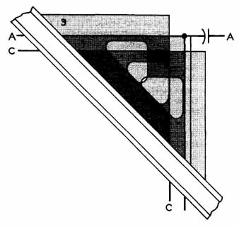
FIG. 15. Drawing a line perpendicular to another line.
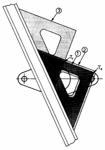
FIG. 16. Drawing a line tangent to two circles and locating tangent
points.
5. Draw a section of sheet metal rounding a curve. Use a compass and
scale, FIG. 17.
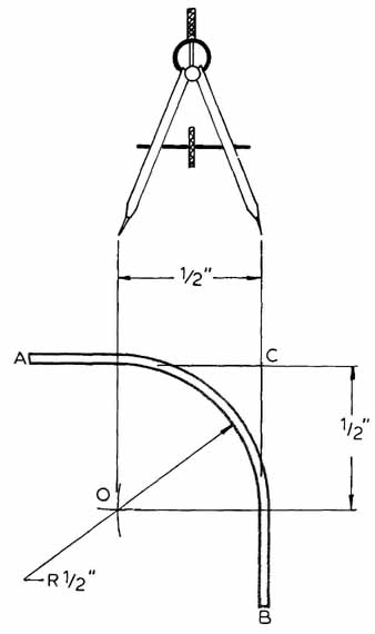
Sample Problem:
Bend sheet metal around 1/2 in. radius. Metal is .12 in. thick.
a. Set compass to make 1/2 in. arc.
b. Set compass at point C and mark off 1/2 in. distance on lines CA and CB.
c. Move compass down line CB to 1/2 in. mark. Draw a new 1/2 in. arc going through 0.
d. Move compass down line AC to 1/2 in. mark. Draw a new 1/2 in. arc going through 0 intersecting arc drawn in step (c). This will be the center of the sheet metal’s radius.
e. Set compass at 0 and draw a 1/2 in. arc striking lines CA and CB at 1/2 in. tangent points.
FIG. 1 7. Drawing a section of sheet metal rounding a curve.
f. Set compass to make a .62 in. radius (.5C + .12).
g. Locate compass at 0 and swing an arc parallel to 1/2 in. arc.
h. Connect straight lines at tangent points.
6. Divide a space into a number of equal parts and draw parallel lines using a scale, triangles, and straightedge, FIG. 18.
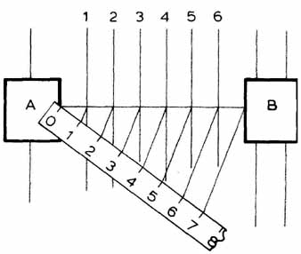
FIG. 18. Dividing an area into equal units.
Sample Problem:
Draw six equally spaced parallel lines between component A and component B.
a. Draw a line between A and B.
b. Set scale with zero on component A at line.
c. At any angle, lay off seven equal convenient spaces (to obtain six equally spaced lines).
d. Connect the seventh measurement to B at line.
e. Draw six lines parallel to line 7-B to intersect line drawn between A and B.
f. Draw new vertical lines through intersections parallel to existing lines.
7. Draw a hexagon with a 1/2 in. distance across the flats. Use a compass, 30-60 triangle, and straightedge, FIG. 19.
Sample Problem:
Draw a hexagonal fastener with a 1/2 in. measurement across the flats.
a. Set the compass to measure 1/4 in.
b. Draw a 1/2 in. diameter circle.
c. Construct vertical and horizontal center lines through the circle center point.
d. Set straightedge parallel to horizontal center line.
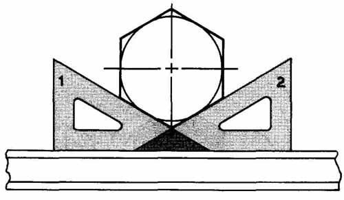
FIG. 19. To draw a hexagon, use 30-degree angles.
e. With the 30-60 triangle, construct tangent tines to outside of circle.
f. Draw vertical lines to complete hexagon.
ORTHOGRAPHIC DRAWINGS
The term orthographic projection means: Projection in which the projecting lines are perpendicular to the image shown, FIG. 20. Orthographic drawings are normally two or more views of an object. Each view is of a different side. Orthographic drawings have six principal views. You must learn to choose which ones are important to the reading of the drawing. See FIG. 21. At times, the six principle views will not show the object adequately. To show an inclined surface or feature more clearly, you will need to draw an auxiliary view.
LINE OF SIGHT
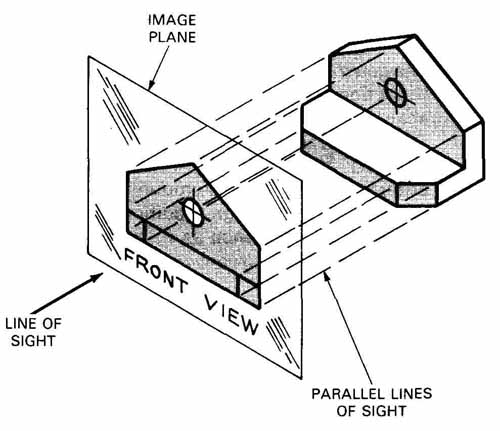
FIG. 20. Each line projected from the object wilt strike the image
plane at a perpendicular angle. Note: All the lines are parallel to each
other.
AUXILIARY VIEWS
Auxiliary surfaces are those which appear as inclined surfaces in normal views. Auxiliary views are used for determining true size and shape of a surface or angle. A plane’s true shape can only be seen when the direction of view is perpendicular to the plane, FIG. 22.
SECTIONAL VIEWS
When a part’s interior features are too complicated to explain with hidden lines, sectional views are used. A sectional view is created by cutting away material to reveal the interior features, FIG. 23. In electronics assemblies, we often need section cuts through the chassis to show how the assembled parts go together, FIG. 24. Sectional views, then, serve the functions of:
1. Adding clarity.
2. Helping in assembly of parts.
DRAWING TITLE BLOCKS
Most companies will have their own title block. FIG. 25 shows the general information given in the title block. Let’s examine the parts drafters fill in. Follow the number labels in FIG. 25.
1. Most companies will require the drafters to letter their names and date of completion.
2. The checker will sign in this space and date the completion of the check. The checker will sign only after all the drawing’s information has been checked.
3. The engineer in charge will sign and date the approval block. The engineer’s signature will verify that the drawing is correct and ready for release.
4. This block is for special remarks.
5. Preliminary release will be signed by the engineering supervisor. This signature will allow copies of the drawing to be distributed to manufacturing and purchasing.
6. Final drawing release will be signed by the engineering supervisor only after the signatures have been made in block 7 and 8.
7. Manufacturing will sign this block. The signature will state that the item can be manufactured and that the design is economically feasible.
8. Purchasing must be able to buy the material, hardware, or components. If the purchasing officials see a problem, they will not sign until they have conferred with the engineers.
9. Reproduction processes will not create an exact scale of the drafter’s work, so no attemptshould be made to measure the blueline prints or other reproductions.
10. The company’s name and address will fill this block.
11. The title of the drawing will be lettered here. Room is provided for three lines in the title.
PARALLEL LINES OF SIGHT
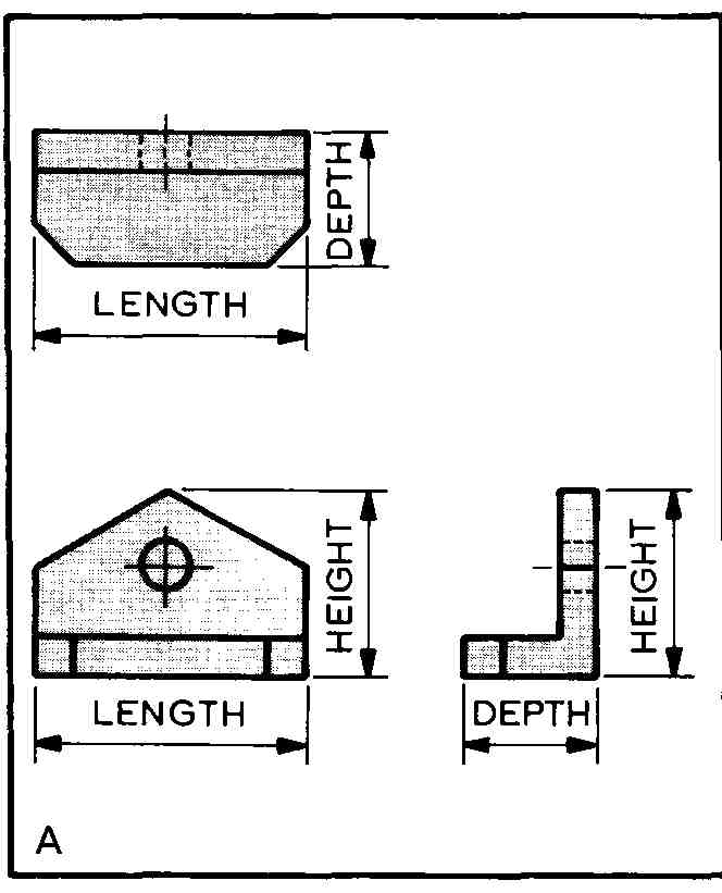
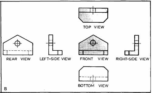
FIG. 21. A—This is a three view orthographic drawing. The front and
right side views show height. Top and front show length. Top and right
side views show thickness. B—The six primary orthographic views. Note:
The left side, bottom, and rear views add nothing to the content. They
should not be drawn.
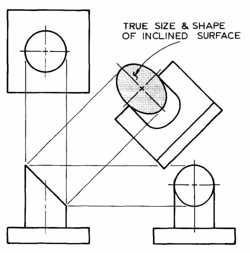
FIG. 22. An auxiliary projection drawing. To see the true size and
shape of a surface, project 90-degree from it to the image plane.
12. The size of the original drawing format will be given here.
13. Each company will have a code number. This number will normally be five digits. These numbers are listed in the Handbook for Federal Supply Code for manufacturers, name and code.
14. The drawing number will come from a Drawing Title and Number book.
15. Each time a drawing is changed, it is given a drawing revision letter. The first change will be identified “A.” Each successive change will use the next letter of the alphabet, except that ‘‘I,’’ ‘‘0,’’ JIQ ‘‘X,’’ are not used.
16. The general scale of the drawing is given here. If sections or details are drawn at different scales, they will be indicated on the drawing.
17. The unit weight will be written only when required.
18. Enter sheet one of total amount on sheet one of multisheet drawings. Additional sheets are numbered in sequence as follows: “sheet 2 of 4,” etc.
TYPES OF DRAWINGS
The electronics drafter will create many kinds of drawings. These can be mechanical drawings as well as electronics drawings. A summary of the common types is given in FIG. 26. Some of the drawing types are used for quality control, manufacturing, research and development, or marketing.
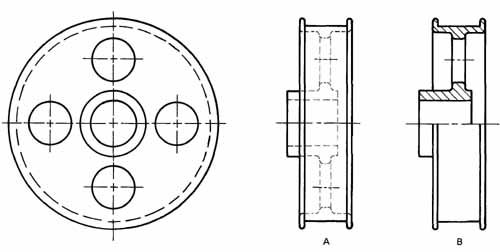
FIG. 23. A pulley with two right side views. A—Hidden lines describe
the interior features. B—Material is cut away to show the interior features.
View B is a half section.
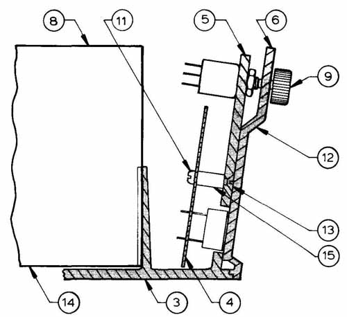
FIG. 24. A section cut showing the internal assembly of an electronic
machine.
This guide discusses only a few of the subjects in detail. You may wish to consult specialized drafting books for more information.
COMPUTER-AIDED DESIGN
Computer-aided design (CAD) was pioneered in the electronics and the aerospace industries. CAD allows the drafter to create, store, and alter engineering drawings using a computer, FIG. 27. This technological advancement has the potential to change and improve industrial productivity as much as any technological development since electricity.
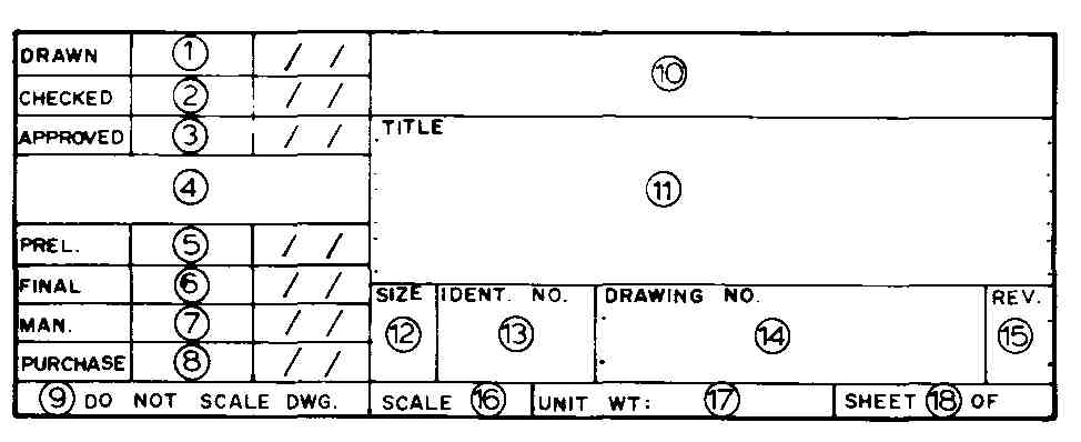
FIG. 25. A typical drawing title block.
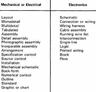
FIG. 26. Types of drawings needed for quality control, design, or production.
Computer-aided manufacturing ( CAM) is the logical extension of CAD. CAD/CAM systems have been successful in providing solutions to some of industry’s oldest problems. One of the main problems has been the historical separation of engineering and manufacturing. This separation causes a breakdown in communication, and shows the transfer of data between engineering and manufacturing.
Communication suffers when drawings are sent from engineering to manufacturing with inadequate or incomplete dimensioning, omitted part callouts, incorrect materials listed, and other errors. The computer helps in eliminating these costly errors.
Poor data causes many problems. Obsolete drawings used in manufacturing result in rejected parts. This causes a waste of time and materials. To solve this problem in a traditional way, we strive to get the latest blueline prints to manufacturing immediately after completing the drafting work. Drawing management does not always make this transfer of data in a timely manner. CAD/CAM can aid management with these problems.
CAD/CAM can help management with the engineering and manufacturing communications problem. Both departments have computer terminals which are linked to the same data bank. This allows manufacturing to use the computer to verify the latest drawing update. Manufacturing can, with the aid of the computer, instantly call up for review any print it desires, saving valuable time and storage space.
CAD/CAM FUNCTIONS
The main purpose of CAD/CAM is to relieve the drafter and assembler of the boredom of doing repetitive tasks. When you have common tasks to perform, you can program the computer to do their for you.
The computer can also be used as an analytical tool. It can save you hours of computation time because it can verify designs and functions. Ii avoids the old production by trial and error. Fig 2-28 shows how CAD/CAM works on a circuit board process.
The computer can control harness assemblies, panel assemblies, flow diagrams, and most electronic drawings. This work is possible because 01 the repetitive nature of these drawings.
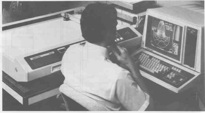
FIG. 27. New designs can be tried on a computer-aided design system.
Note plotter used to provide hard copy. (Tektronix, Inc.)
With printed circuits and integrated semiconductor circuits, the demand for size and increased drafting output makes the computer system necessary. A drafter cannot manually match the accuracy and speed of the computer when doing high density printed circuit design.
CAD has some advantages for the drafter. These advantages are:
1. Standard symbols or objects can be stored by the computer. Then as the drafter requires a symbol or object, the symbol can simply be “CALLED UP,” saving valuable time required to draw it again. “Call up” means to recall it from the computer’s memory. The computer will also copy any feature or group of features you have on a drawing.
2. It allows a quick and easy storage file. Once a drawing has been completed. It can be saved in the computer’s storage system. Later, you can call up the drawing for design changes, analysis, or other engineering requirements. Storage files are normally magnetic tape or disk recordings.
3. Drawings can be created more quickly and accurately. The more complex the drawing, the greater the time savings. Some companies require the computer to save 80% of their drafting Costs. If the computer cannot do this, the company may choose traditional drafting methods.
4. The CAD drawing can be produced to ±.001 in. accuracy, depending on the plotter. Traditional drafting methods will not allow for a timely completion of a drawing to this accuracy.
5. Drawing changes can be made much easier. Areas of the drawing can be deleted and new detail added without laborious erasing and redrawing.
6. When combined with CAM, it becomes a very powerful tool for both engineering and manufacturing. An example is in printed circuit board design. The CAD information is used in all steps through the final inspection of the completed board.
7. Prototype drawings can be quickly altered to show many design possibilities. Parts can be moved to show possible interferences or design errors. Mating parts can be drawn on different layers so that you can display one, or both, at the same time to check their mating features.
8. Automatic parts lists can be created by placing a hidden parts number below the symbol. When a resistor of a specific value is added to a drawing, an invisible part number is also added. After the drawing is completed, the computer can scan the drawing, and list the following:
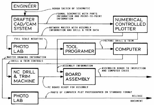
FIG. 28. A CAD/CAM system can be part of a process for designing and
manufacturing printed circuit boards.
a. Part number.
b. Quantity of parts.
c. Parts description.
The computer can compile large parts lists in minutes.
After reading this list of existing possibilities, you may ask, “Will computers replace drafters?” Most companies say no. They see the drafter using the computer as an added tool. The computer will allow the drafter to do more engineering design, data transfer, and pattern drawing control.
Drafters will be needed to generate data banks. As new engineering data is generated, the banks of data will need to be updated. Besides using this data to create graphics, the drafter will be more in touch with management. The data bank established by the drafter will be needed for management control. For example, purchasing, production, and ac counting will all need drafting-generated computer information.
COMPUTER SYSTEM PARTS
In addition to software, the computer requires hardware in order to be useful graphics tool. Some of the hardware parts are described in the following list.
CENTRAL PROCESSING UNIT (CPU)
The CPU is the brain of the system. It works with the data, and it executes the commands. The CPU also contains the computer’s temporary memory.
MONITOR
The monitor displays the communication between you and the computer, and vice-versa. The monitor also works as a graphics display.
PLOTTER
The plotter creates a HARD COPY (paper copy), as opposed to the SOFT COPY (electronic image) the monitor produces, of the data. Soft copy is lost when the power is turned off.
KEYBOARD
The keyboard is one way to in put data to the computer. It is similar to a typewriter keyboard, and it can easily be operated by a trained typist. The drafter can make alphanumeric inputs on a normal keyboard, but many computers have additional function keys.
MOUSE
A mouse is an effective way to input graphic data to the computer. It allows information to be entered easily by moving the hand-held mouse across a flat surface.
MODEM
The word modem stands for modulator/demodulator. The modem is a telephone linkage unit. It connects a computer to a data source or to another computer over the telephone lines.
DISK DRIVE
A disk drive is an I/O (input/output) devise. It can feed the computer prerecorded information or can be used for storage of the output data.
COMPUTERS IN ELECTRONIC COMPANIES
The CAD systems have chiefly been used to lay out printed circuit boards and integrated semiconductor circuits. But they are now being used to analyze circuits. This is done at different levels of completion:
1. When the engineer finishes the design, the computer can help check it.
2. It will check the printed circuit artwork. It checks completeness and accuracy of the artwork.
3. A final check on the assembled circuit board will disclose any bad components or board errors. Another area where the computer is aiding design is in mechanical packaging. This is accomplished by modeling the parts or package.
REVIEW QUESTIONS
1. Why should electronics drawings be completed with high quality?
2. What requirements mandate the 5/32 in. lettering?
3. List the reasons for standardization in drawing sheet sizes.
4. How many primary views are there in orthographic projection?
5. Auxiliary views serve what main purpose?
6. What view will be drawn when we need to see internal features?
7. When will lower case lettering normally be used?
Draw a perpendicular to a given line.
Construct a tangent line between a 2.00 dia. and 1.00 dia. circle spaced on 2.00 inch centers.
Draw a hexagon shape with a 2.00 in, measurement across the flats.
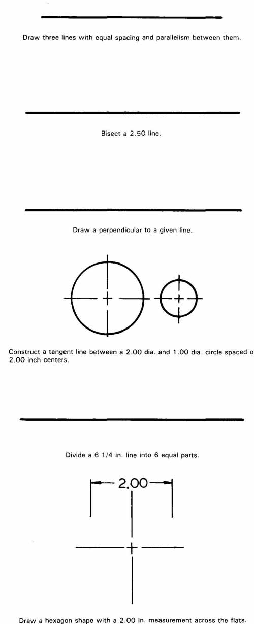
FIG. 29. Draw the above problems using techniques shown earlier in
the Section.
Draw three lines with equal spacing and parallelism between them.
Bisect a 2.50 line.
8. Drawings larger than “E” size are __________ sized format.
9. Why are thin lead pencils becoming popular in the drafting field?
10. To draw long pencil lines that are sharp, you should:
a. Stop often to sharpen the pencil.
b. Use three or more pencils in succession.
c. Use a vary hard lead in the holder.
d. Rotate the pencil while drawing.
e. Statements c and d above.
11. Make two or more parallel lines using a straightedge and a __________
12. What potential will the computer have in industry?
13. CAM means:
a. Computer Assembly and Maintenance.
b. Computer-Aided Machining.
c. Computer-Aided Manufacturing.
d. Computing and Machining.
14. A CAD system should save at least __________% of drafting costs.
15. List some advantages of CAD.
16. Will the computer replace the drafter? Explain.
17. What is hard copy and soft copy?
PROBLEMS
PROB. 1. Letter the alphabet using gothic upper case vertical letters. Your instructor will establish the requirements.
PROB. 2. Letter freehand the following information using upper case vertical lettering and guide lines:
NOTE:
1. UNLESS OTHERWISE SPECIFIED:
RESITANCE VALUES ARE IN OHMS, 1/4W, and 10% CAPACI TANCE VALUES ARE IN MICRO FARADS, 35V, and 5%
2. SOLDER ALL TERMINATIONS PER TAYLOR WORKMANSHIP STAN DARDS
3. THIS DRAWING TO BE USED IN CONJUNCTION WITH ASSEMBLY DRAWING 780629-5
Letter the alphabet using lower case lettering. Your instructor will establish the requirements.
On a separate paper, complete the geometric exercises in FIG. 29. Draw the necessary orthographic views of the part shown in FIG. 30. On a separate sheet, draw the two existing views and an auxiliary view of the part which is shown in FIG. 31.
Divide a 6 1/4 in. line into 6 equal parts.
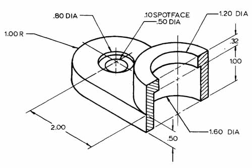
FIG. 30. Draw the necessary orthographic views of the part.
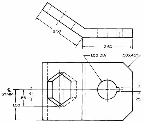
FIG. 31.
Draw the two existing orthographic views and add the missing auxiliary
view.