AMAZON multi-meters discounts AMAZON oscilloscope discounts
After studying this Section, you will be able to:
- Explain the advantages of pictorial drawings.
- Make an isometric pictorial drawing.
- Define axonometric, isometric, and oblique projection.
- Explain exploded views.
- List the steps for making isometric drawings.
Electronics drafters are often asked to create pictorial drawings. These drawings are required to direct manufacturing, marketing, maintenance, and assembly personnel. People who are untrained may not be able to read or understand multi-view drawings (orthographic), but they can read pictorial drawings because they are more like the physical part. Pictorials clearly convey needed information to all readers. You will study two types of pictorial drawings: Axonometrics and Obliques.
AXONOMETRIC DRAWINGS
Axonometric drawings are pictorial drawings in which the projection lines remain parallel. This is not normally what you would see with your eyes. Your eyes would perceive the projection lines con verging as they recede in the distance. See FIG. 1. Axonometric drawings are the most frequently used pictorials even though they are visually distorted.
There are three main types of axonometric drawings: isometric, di-metric, and trimetric, FIG. 2. You will study isometric drawings. These are the type electronics drafters most often use.
ISOMETRIC DRAWINGS
Isometric drawings are made with the two receding axes at 30 degrees off the horizontal and with the third axis vertical. See FIG. 3. The three axis lines may be drawn and measured true length. An isometric cube will be revolved 45 degrees and then tilted forward 35 degree 16’. The 35 degrees 16’ is the angle between the horizontal plane and the line of sight, FIG. 4. An isometric drawing is about 1 1/4 times the size of a true representation. To show this, we will use a one inch square cube. For an isometric ellipse to fit this cube, it will have to be a 1 1/4 in. size, FIG. 5. If an isometric ellipse template is used, the template will have the 1 1/4 times size included in each ellipse size.
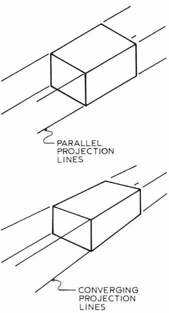
FIG. 1. Compare the axonometric and the natural projection. In the
natural projection, the lines converge as they recede.
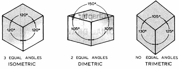
FIG. 2. Three main types of axonometric drawings.
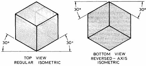
FIG. 3. An isometric cube drawn with regular and reversed axis.
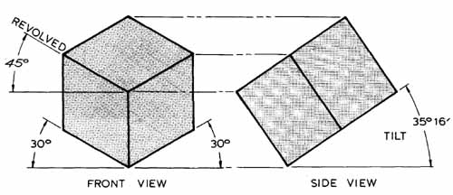
FIG. 4. A cube rotated and tilted for an isometric drawing.
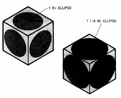
FIG. 5. Two isometric cubes with each axis drawn one inch long. Note
that it takes a 1 1/4 in. ellipse to fit the surfaces.
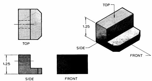
FIG. 6. An isometric drawing created from three orthographic views.
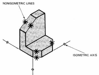
FIG. 7. An isometric view with non-isometric lines. These lines are
not parallel to the isometric axis lines.
ISOMETRIC FROM ORTHOGRAPHIC
An isometric drawing will be based on the three orthographic views. Dimensions from the orthographic views can be transferred directly to the isometric. See FIG. 6. Dimensions can be transferred by using a scale or dividers.
All lines are measurable except nonisometric lines. These lines are not parallel to one of the isometric axes, FIG. 7. Nonisometric lines cannot be measured, but must be plotted. FIG. 8 shows how to plot nonisometric lines as points from the orthographic view.
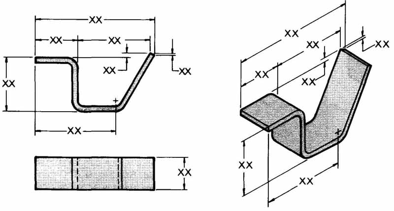
FIG. 8. How to plot non-isometric lines from orthographic views of oblique
surfaces. Draw a box to enclose the item. Only use measurements along
the directions of the edges of the box.
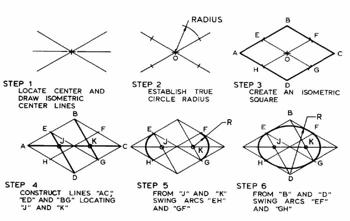
FIG. 9. The steps for creating an ellipse using a compass.
DRAWING AN ISOMETRIC ELLIPSE USING A COMPASS
The illustrator is often required to draw ellipses. Using a compass, you can draw an approximate ellipse. The compass method most often used is the FOUR-CENTER method. FIG. 9 shows the steps required to construct an isometric ellipse.
DRAWING AN ELLIPSE WITH TEMPLATE
An ellipse template, FIG. 10, is used to draw circular objects in isometric. The isometric ellipse is a 35°16’ ellipse and can be used on all true isometric surfaces.
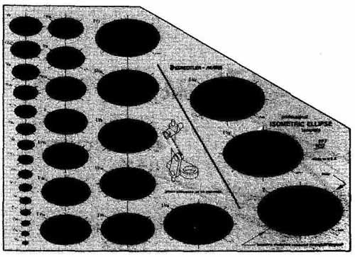
FIG. 10. Ellipse template. (Staedtler—Mars)
You are also required to draw ellipses on other than true isometric surfaces. FIG. 11 shows how ellipse requirements change on nonisometric surfaces. An isometric protractor can be used to give us the required ellipse degree, FIG. 12. The isometric template may also give you the measuring value for each nonisometric line. FIG. 13 shows a table used on some ellipse protractors.
In order to use an ellipse template, you must learn some terms: the MAJOR and MINOR axis. The major axis is the largest measurement across the ellipse. The minor axis is the shortest distance across the ellipse. When placing the ellipse, you must be concerned about the axis. FIG. 14 shows how to align the ellipse on an isometric cube. The most important thing to remember is that the minor axis will align with the shaft or hole’s longitudinal center line.
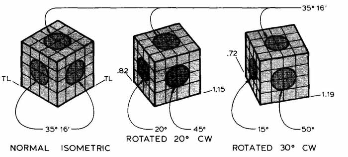
FIG. 11. Ellipse requirements for various viewing angles. An isometric
protractor is used.
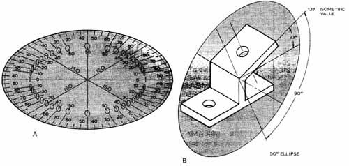
FIG. 12. A—An isometric protractor provides angles for drawing ellipses.
B—An isometric protractor being used to establish the surface angle and
ellipse requirement.
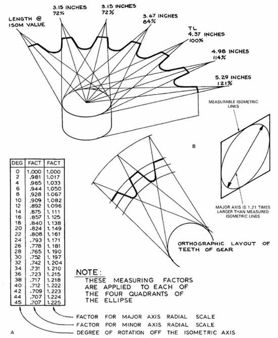
FIG. 13. A—Table shows measuring factors for each amount of rotation
off the isometric axis in degrees. B—See how values apply on gear. TL
means true length.
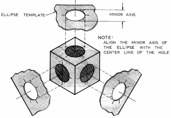
FIG. 14. How to place an ellipse on an isometric drawing.
LONG AXIS ISOMETRIC
Long axis isometrics are drawn with the long axis horizontal and the vertical axis as a 60 degree angle, FIG. 15. When adding holes in this isometric drawing, the ellipse template will be used differently. On vertical surfaces the minor axis of the ellipse will be parallel to one 60-degree line. On horizontal surfaces the minor axis will be parallel to the other 60° axis.
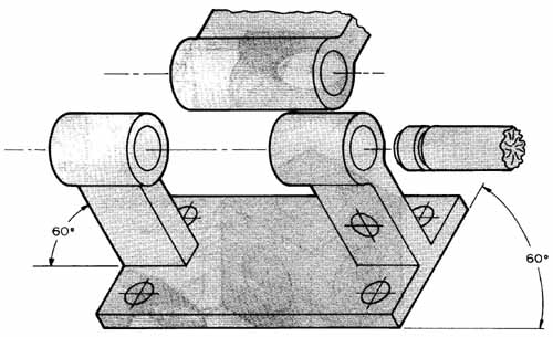
FIG. 15. A long axis isometric with vertical lines running at 60° off
the horizontal. On horizontal surfaces, align the ellipse minor axis
with 60-degree axis on left side of drawing. On vertical surface, align
minor axis with other 60-degree axis.
ISOMETRIC FREEHAND SKETCHING
The initial stage for drawing isometrics is to sketch out your idea or concept. A sketch is also a valuable tool for communicating with your colleagues, engineers, and others with whom you will work. Most manufactured items start as an idea which is sketched out on paper. A simple sketch can often communicate more clearly than thousands of words. For the sketch to have full value, it must be in good proportion and include the basic detail which will appear on the finished drawing, FIG. 16.
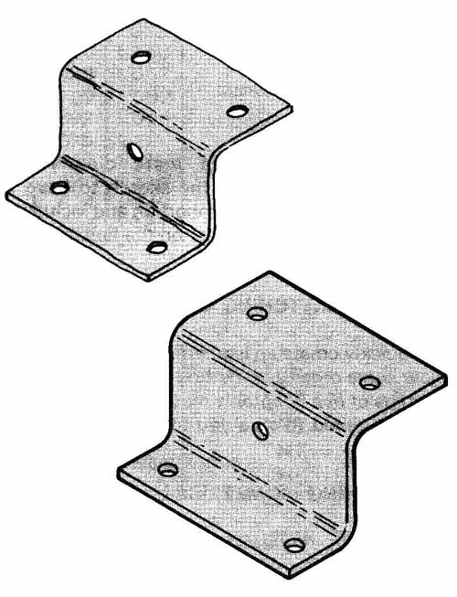
FIG. 16. Show the detail in a sketch when preparing for
a drawing.
STEPS FOR SKETCHING ISOMETRICS
To quickly create an isometric sketch, you should follow some organized method. FIG. 17 will show the steps of one adaptable method. Note how each step is required to give you total control over the final result.
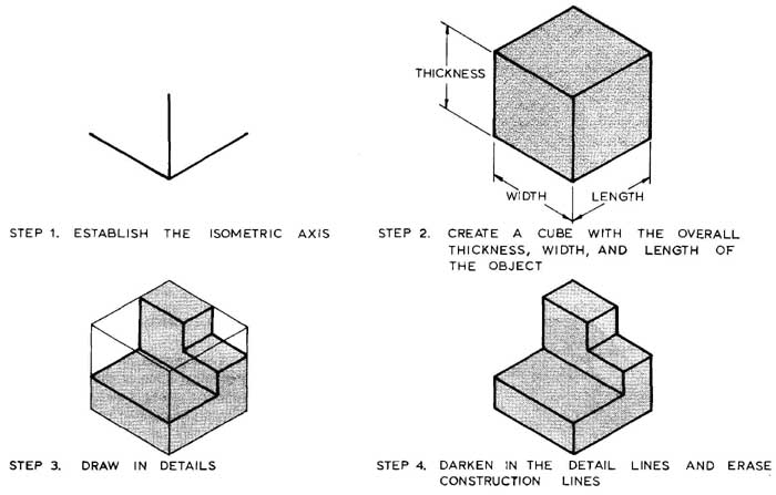
FIG. 17. There are four basic steps in creating an isometric sketch.
Enclosing or ‘ in” an object helps avoid distorted drawings.
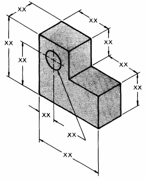
FIG. 18. Applying dimensions to a pictorial drawing.
DIMENSIONING ISOMETRICS
It is often required that you dimension an isometric drawing. The dimensions lend additional information and understanding for the reader. With the increased use of illustrations for manufacturing, it is necessary for you to understand dimension techniques. See FIG. 18.
OBLIQUE DRAWINGS
Oblique drawings are sometimes used to show electronics equipment. The drawing is three dimensional with one surface parallel to the image plane. The other two surfaces will recede at some angle off the horizontal, FIG. 19. The angle is usually 30-degree, 45-degree, or 60-degree because of the convenience of standard triangles. All of the dimensions on the drawing’s three main axes can be scaled.
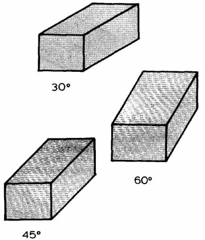
FIG. 19. Basic oblique drawings.
SELECTING THE VIEW
The surface with the most features should be placed parallel to the image plane. This will allow you to see these features with the least amount of distortion. FIG. 20 shows an electronics unit drawn using this principle. The longest axis may also influence the choice of surface parallel to the image plane. The choice should minimize distortion on the long axis.
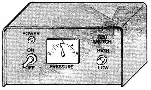
FIG. 20. This electronics unit is drawn in oblique so the front panel
is not distorted.
CAVALIER OBLIQUES
When an oblique drawing is laid out with the receding axis at 45 degree, we call it a true cavalier. FIG. 16. Show the detail in a sketch when preparing for General cavaliers may be drawn at any angle be a drawing btween 0 and 90°. See FIG. 21. All axis measurements are full measurement. This makes it easy to draw and measure the finished dimensions. A cavalier drawing distorts the object’s true dimensions. To help eliminate this distortion, cabinet obliques are used.
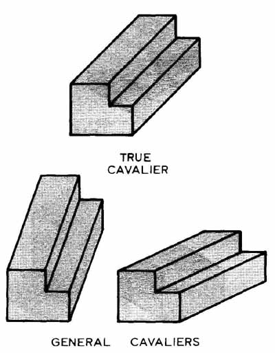
FIG. 21. Cavalier drawings drawn at different angles.
CABINET OBLIQUES
This oblique may be drawn at any receding angle. But the receding axis will be drawn 1/2 size. See FIG. 22. This shortening of the receding axis will minimize the distortion seen in the cavalier.
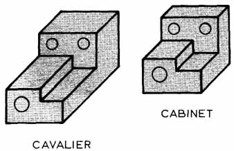
FIG. 22. Minimize visual distortion by drawing a cabinet oblique.
HOLES IN OBLIQUE DRAWINGS
It is possible to use templates or a compass to create holes or cylindrical shapes on oblique drawings. The front surface is easiest, as all the shapes are true. But circles on receding surfaces will need to be designed. You can use the four-center method, FIG. 23. Or you can establish the hole’s “Y” and ‘2” dimensions so an ellipse template may be used, FIG. 24.
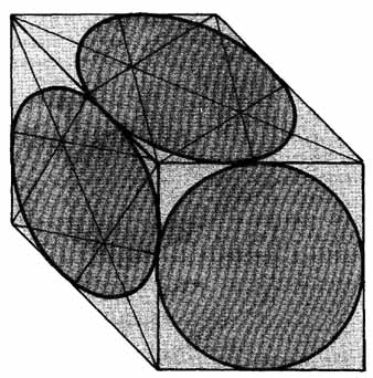
FIG. 23. Drawing a hole in an oblique surface using the four-center
method.
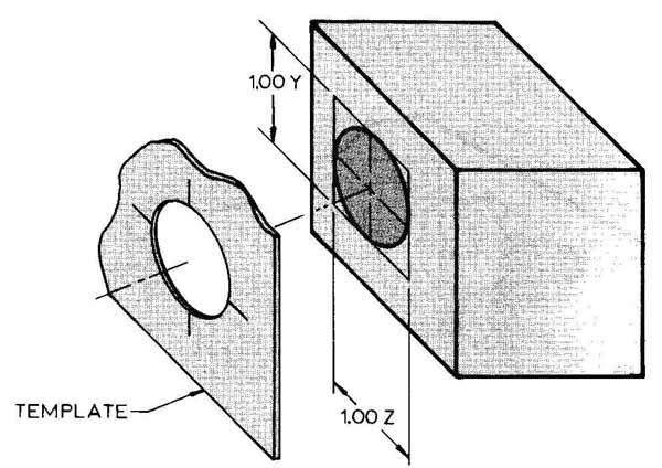
FIG. 24. To draw hole on oblique drawing, lay out the Y and Z dimensions.
Then select an ellipse that fits best.
EXPLODED DRAWINGS
Exploded drawings are used extensively for assembly and maintenance documents. They show how the individual parts fit together, FIG. 25. Each part will be numbered so it can be found in a parts list or parts catalog. The parts list or parts catalog will give a full description for each part.
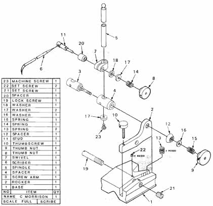
FIG. 25. An exploded drawing used for assembly.
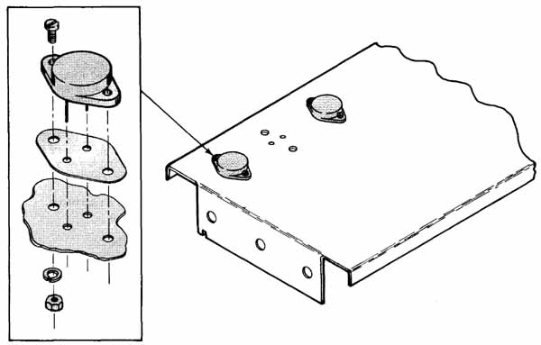
FIG. 26. Details show items too small to draw clearly.
Often small features or parts will have to be shown more clearly than the scaled drawing allows.
A detail of the part or feature will be needed. FIG. 26 shows a method used by many illustrators.
REVIEW QUESTIONS
1. What are some uses for pictorial drawings?
2. Why is freehand sketching important?
3. List three axonometric drawings.
4. What is meant by boxing in?
5. List steps for sketching an isometric.
CASE IS COLLECTOR
7. An isometric drawing is about ______ times the size of a true representation.
a. 0.75
b. 0.90
c. 1.50
d. 1.25
8. What are nonisometric lines?
9. Describe the major axis.
10. Align the ____ (major, minor) ellipse axis with the centerline of a shaft.
PROBLEMS
PROB. 1. Prepare an isometric drawing for the transistor in FIG. 27.
PROB. 2. Make a full scale oblique drawing of the electrical motor in FIG. 28.
PROB. 3. Obtain some broken electronic equipment for your class. Take this apart and draft an exploded isometric showing how parts are assembled.
PROB. 4. Ask your instructor for electronic components to draw pictorially.
PROB. 5. Create a cabinet oblique drawing of an electronic device.
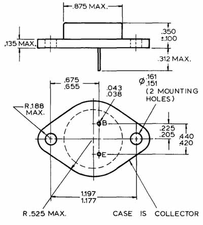
FIG. 27. A typical power transistor body. Prepare an isometric drawing.
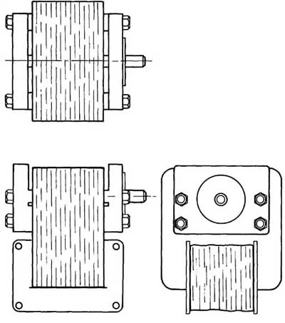
FIG. 28. An alternating current motor. Make an oblique drawing.