AMAZON multi-meters discounts AMAZON oscilloscope discounts
After studying this Section you will be able to:
- State the process and identify fasteners for fastening metal parts.
- List the qualities of electronics packaging materials.
- Describe welding processes and apply symbols to call out welds.
- Calculate bend allowances for sheet metal packaging and lay out stretch-outs for sheet metal parts.
- Apply rules of good dimensioning to mechanical drawings.
INTRODUCTION
The word packaging refers to the process of put ting the electronics into a housing designed for the environment and for safety. The career title for this area of drafting work is Packaging Drafter. The field involves drafting of structural shapes for solid parts, rather than drafting of electronic circuits. Electronics drafting is involved only as a guide to part locations, mounting methods, and other mechanical requirements.
In this Section, you will study the processes needed to make these enclosures. You will start your study with fastening processes.
FASTENING
The basic means of putting parts together is called fastening. Fastening is accomplished by welding, mechanical fasteners, or bonding with adhesives. These fastening methods are used at the subassembly and assembly level.
WELDING
Welding can be used wherever we want the parts permanently joined. Welding is accomplished by using heat, pressure, or both. The preferred welding methods are: gas, arc, resistance, and adhesive. FIG. 1 shows the process of arc welding.
Gas welding makes use of burning gases to produce the welding temperature, FIG. 2. When the heat melts the metals, they will fuse together. Filler material may also be used in this process. The filler material will normally be similar to the composition of the base metals.
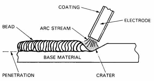
FIG. 1. Arc welding is a joining process that uses an electric arc
to produce the heat required to melt the metals. The melting of the metals
allows them to fuse together. Filler metal from the electrode may be
added to the joint.
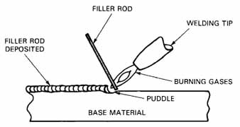
FIG. 2. Gas welding using a filler rod to deposit additional material.
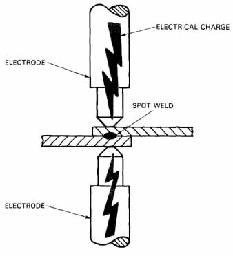
FIG. 3. Materials to be spot welded are placed between electrodes.
The electrodes are then pressed together while an electrical charge is
applied. This charge melts a spot between the metals because of their
resistance. When the spot has cooled, the electrodes open up. This allows
the part to be moved to the next spot weld or removed for the next part.
Resistance welding is the process of welding by heat and pressure. Spot welding is the most common form of resistance welding, FIG. 3. The weld is produced by heat obtained from the resistance of the material to the flow of electrical current. This process is used for its advantages in electronics packaging. Resistance welding is economical and gives weight savings, since it uses no additional filler metal. The welds are made directly between the metal parts being joined.
MECHANICAL FASTENERS
Mechanical fasteners have been used for centuries to join parts together. In the family of mechanical fasteners there are screws, bolts, pins, and keys. These fasteners allow the joined parts to be easily separated. Riveted and press-fit joints are considered more permanent.
Fastening parts with mechanical fasteners re quires skill in the preparation of the parts being joined. It is a costly way to join parts, but maintenance and inspection of some parts require this method for ease of disassembling.
SCREWS
Screws use the principle of the wedge to clamp an assembly together. Screws are the most common mechanical fastener in electronics.
Machine screws are available in many different head styles, FIG. 4. Each screw type has a special application. For example, if you want a screw to be flush with the material being joined, you would select a flat head screw. These screws can be turned by different drivers, FIG. 5. The socket and hex head screws allow a fastener to be tightened to a high torque level.
Screw Threads
Machine screws come in three main thread types, unified national coarse (UNC), fine (UNF), and extra fine (UNEF). The number of threads per inch in relationship to the diameter dictates the thread type, as listed in FIG. 6.
SELF-TAPPING SCREWS
In electronics, there are many applications for self-tapping screws. Refer to FIG. 7. Self-tapping screws work well on thin material and save the expense of the costly tapping operation. This thread type also works well in plastic parts.
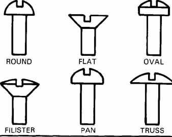
FIG. 4. Some of the head styles of machine screws.

FIG. 5. Different screw drives are required for each of these head
types.
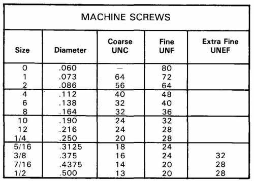
FIG. 6. A table of machine screw sizes including thread classification
by threads per inch.
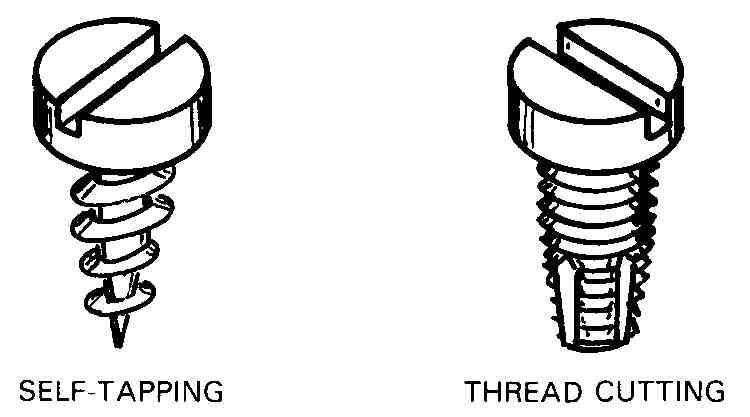
FIG. 7. Sheet metal screws include a self-tapping screw and a thread
cutting screw that requires a clearance hole to start the thread.
BOLTS
Machine bolts are used to assemble items that do not require close tolerance fasteners. They are manufactured with square, hex, and socket heads, FIG. 8. Bolts are normally furnished with nuts.
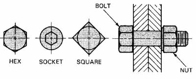
FIG. 8. A bolt and nut with examples of head types.
PINS
Pins are used to retain parts in position. See FIG. 9. With a washer, pins may be fitted into a hole drilled crosswise in a shaft to prevent parts from slipping or spinning off.
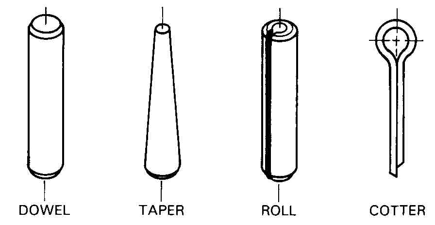
FIG. 9. Pins are used for locating and holding parts in position.
Flat washers come in four different styles: light, medium, heavy-duty, and extra heavy-duty. Flat washers prevent marring of the surface finish by turning. Split-ring lock washers are used to prevent fasteners from loosening under vibration. External- tooth lock washers have electronic advantages other than their superior holding power. They cut into the chassis when the fastener is tightened, making it possible to get a high quality ground connection. Internal-tooth lock washers are not as effective as external type but they are desirable when appearance dictates a clean non-snagging surface.
WASHERS
Washers provide an increased surface area for bolt heads and nuts. They distribute the load over a larger area. There are four main washers used in electronics: flat washers, split-ring lock washers, external-tooth lock, and internal-tooth lock. Examples are shown in FIG. 10.
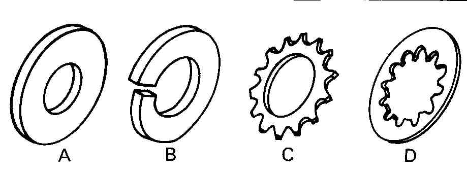
FIG. 10. The most often used washers in the electronics industry. A—Plain
flat washer. B—Split-ring type. C— External-tooth lock washer. D—internal-tooth
lock washer.
MACHINE SCREWS
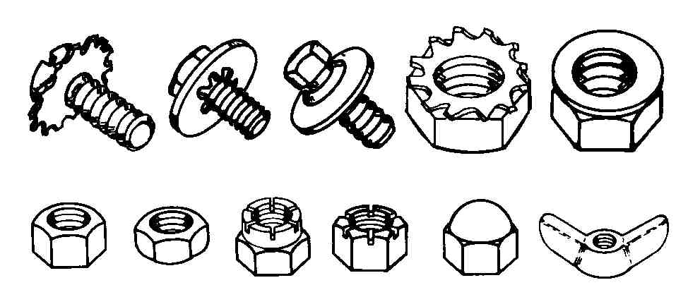
FIG. 11. A—Some screws and nuts are pre-assembled with washers. There
are many nut styles. B—Standard nut. C—Jam nut. D—Slotted and castellated
nuts. E—Cap nut. F—Wing nut.
PRE-ASSEMBLED FASTENERS
Pre-assembled fasteners help cut assembly time. When assembling areas are confined, it is hard to handle separate nuts and washers and secure them to a bolt. Therefore, pre-assembled fasteners save costs and reduce assembly time. FIG. 11A shows some screw units and nut units.
NUTS
Nuts normally have an external hexagonal or square head. They are used with bolts or studs. They come in different types and some have special applications.
The standard nut is the type most used, FIG. 11 B. Other nut types are common. The jam nut, FIG. 11C, is a thinner nut often used to lock a standard nut in place. Castellated and slotted nuts, FIG. 11 D, are manufactured so that you can use a cotter pin to prevent them from loosening. Cap nuts, FIG. 11 E, are applied when appearance and safety are important. Wing nuts, FIG. 11 F, can be loosened and tightened without the use of a wrench. Its shape allows hand adjustment.
RIVETS
Rivets are used to make permanent assemblies. They have been developed for different applications. Therefore, they have different head styles, FIG. 12. A rivet type used frequently in electronics assembly is the pop rivet, or blind rivet, FIG. 13. It has the benefit of not needing a back-up on the far side of the material being riveted.
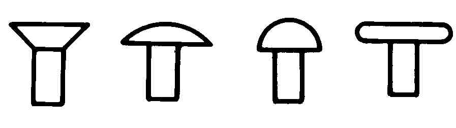
FIG. 12. Rivet styles. A—Countersink. B—Truss head. C—Round head. D—Flat
head.
ADHESIVES
Adhesives are often used to create permanently bonded joints. They can be applied to almost any material. The new synthetic adhesives like epoxy- resin based adhesives are used for many electronic packaging applications. They give a clean appearance and make strong joints.
CLEANING SURFACES
The finishing process cleans, protects, and decorates the surface. Cleaning the surface to free it of dirt, oils, and rust is usually accomplished to prepare the metal for further treatment. Cleaning can be accomplished by chemical or mechanical means. Mechanical methods use abrasives, sand blasting, scraping, and wire brushing. Chemical methods use alkaline cleaning. Once the metal has been cleaned, we must select the appropriate finish.
FINISHES
Finishes are applied for different purposes. Some of these purposes are:
1. Protective coatings: coatings applied to the metal to protect it from corrosion and abrasion, and to hide imperfections.
2. Chemical coating: a thin layer of metallic compound produced by chemical or electrochemical treatment of the surface. Types of finishes are chromates, oxides, and anodized films.
3. Organic coating: a layer of paint, lacquer, enamel, varnish, or primers sprayed or brushed on the metal.
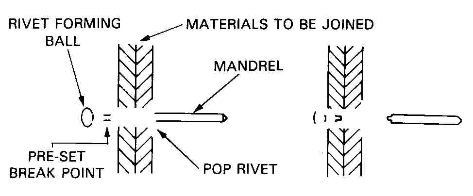
FIG. 13. A—Rivet being set. B—The forming ball has been pulled into
the rivet, forming a head. The mandrel is preset to break after the forming
ball has been seated. The mandrel is pulled with a pop-rivet tool.
4. Metallic coating: a film of metal or metal alloy deposited by chemical, electroplating, hot dip ping, or electrodeless plating processes.
5. Lubricant coating: a film applied to the metal to reduce surface friction. Types of films are oils, waxes, and mineral substances such as graphite.
METALS AND FINISHES
For each metal you must select an appropriate finish. Metals predominately used in electronics packaging are aluminums and steels. The following is a breakdown of standard finishes for these metals.
Aluminums are generally anodized, but they may also be caustic etched or phosphate coated. These preparations can be a preliminary step to the application of organic coatings. Zinc chromate under- coatings will also prepare aluminum for painting.
Steels can be plated with cadmium, copper, nickel, chromium, silver, and gold. An electronic chassis is normally cadmium plated. Zinc chromate under-coatings will prepare steel for organic coatings.
MATERIALS FOR PACKAGING
Material selection for the packaging of electronics components normally involves three areas: plastics, steels, and aluminum material. We begin our study with plastics.
PLASTICS
Plastics are being used more as electronics packages become smaller. Plastics are easily formed into intricate shapes, FIG. 14. Plastics can also be welded or machined. Reinforcing materials can be added to plastics to make them more rigid and to give them strength required in some applications.
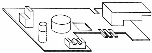
FIG. 14. Support structure for computer disk drive.
There are two general classifications of plastics: thermosetting and thermoplastic. Thermoplastics are those materials which can be heated and re formed. They can also be re-melted and recast like metals. In contrast, thermosetting plastics cannot be reformed once they are solidified into their permanent shape.
THERMOSETTING
Thermosetting plastics are classified into groups. Epoxy, urethane, phenolic, and melamine are some of the group classifications. Epoxy plastics are used in electronics as adhesives, and for electrical insulation, structures resistant to acids, and coating applications. Urethanes are used for good thermal and electrical insulation. Phenolics have hard and elastic properties. They are used for electronics cabinets and printed circuit board applications. Melamines are hard and strong. They can be easily colored and have good resistance to oils. They are used for electrical wiring devices such as terminal blocks.
THERMOPLASTICS
Thermoplastic plastics come in the following groups: ABS (acrylonitrile-butadiene, styrene), acrylics, nylon, vinyls, and cellulosics. ABS plastics are strong and weather resistant. They are used in telephone components. Acrylics are strong and rigid. Their electronic applications are panel windows, light covers, and cabinet paints. Nylons are tough and elastic. They are used for bushings, gears, washers, and hinges. Vinyls are used to add decorative surfaces to electronic cabinets. Cellulosics are tough and have good insulating properties. They are used in the manufacture of drafting templates and equipment. A common electronic use is in telephone sets.
FABRICATING WITH PLASTICS
Plastics can be purchased in standard forms, such as sheets, tubes, structural shapes, and laminates. They can also be purchased as raw material in powders, liquids, or granules.
Plastics bought in standard forms can be cut in to shapes, machined to drawing specifications, or heated and reshaped to desired forms. Thermoforming plastics can be heated and blow-molded or vacuum-formed, FIG. 15. Thermoforming has limitations in what shapes can be produced. When you want intricate shapes, they can more easily be injection molded.
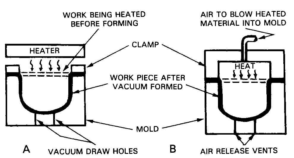
FIG. 15. A—In vacuum-forming, a plastic sheet is heated and drawn into
a mold with a vacuum. B—A blow-forming process.
Injection molding normally requires thermo plastics. The plastic will be purchased in a powder or granular form. It is heated in an injection hopper. When it is in a plastic state, it will be forced by a plunger into a mold, FIG. 1 6. Another way to form plastics is by an extrusion process. Extrusions are made by forcing semiliquid plastic through a pre-shaped die, FIG. 17. Unlimited numbers of shapes can be made by this process. The die can be changed to allow a new shape to be formed.
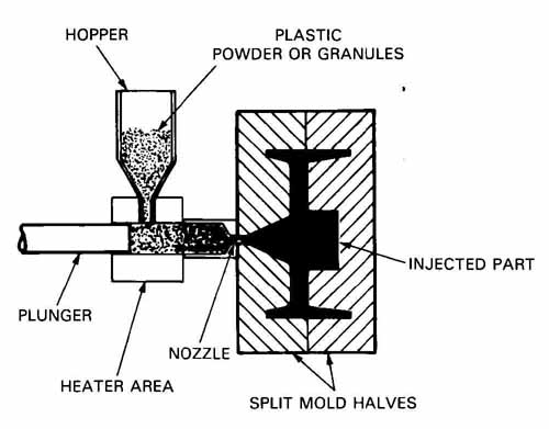
FIG. 16. A simplistic look at the plastic injection process. Note how
the plunger forces the molten plastic through the nozzle and into the
mold cavity.
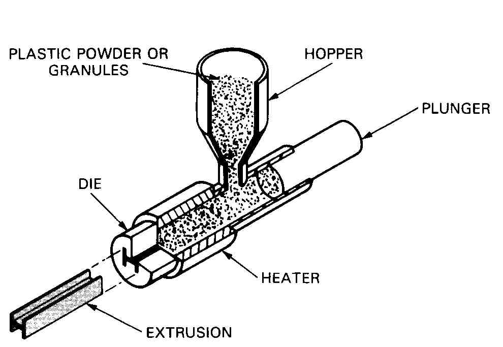
FIG. 17. An illustration of a plastic extrusion process.
ALUMINUMS
Aluminums have at least seven properties which make them desirable for use in electronics. Here is a list of properties:
1. Weight—aluminum weighs less than other metals.
2. Ease of fabrication— it can be easily formed or machined.
3. Corrosion resistance—it needs no protection in most ordinary environments.
4. Finishes easily—there are many finishes which can be economically applied to aluminum.
5. Electrical properties—pound for pound it is twice as conductive as copper. However, with the same cross-sectional area, it conducts 62% as well as copper.
6. Nonmagnetic—this quality makes it a good shield in electronic cables and equipment.
7. Heat dissipation—it transmits heat rapidly. This makes it useful for heat-sinking electrical components that would otherwise burn out.
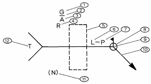
FIG. 18. An American Standard Graphic Symbol for welding. The standard
it follows is ANSI/AWS A2.0. See table above for explanation.
1. SPECIFIES THE FINISH ON THE WELD. G=GRIND, C=CHIP, M=MACHINE.
2. MEANS THE WELD WILL BE FLUSH WITH THE SURFACE. r MEANS A CONVEX SHAPED WELD.
3. SPECIFIES THE INCLUDED ANGLE OF THE COUNTERSINK FOR A PLUG WELD.
4. SPECIFIES THE ROOT SIZE OF A PLUG OR SLOT WELD, FIG. 19.
5. LOCATION OF THE BASIC WELD SYMBOL, FIG. 20.
6. LENGTH OF WELD IN INCHES, FIG. 21.
7. PITCH OR CENTER TO CENTER SPACING OF NONCONTINUOUS WELDS, FIG. 21.
8. SPECIFIES WELD AROUND COMPLETE JOINT, FIG. 22.
9. SPECIFIES WELD IN FIELD. THIS IS USED WHEN ONLY SOME OF THE WELDING WILL BE COMPLETED IN THE SHOP.
10. ARROW POINTING TO WELD JOINT OR GROOVED MEMBER, OR TO BOTH.
11. SPECIFIES NUMBER OF SPOT WELDS, FIG. 23.
12. A CODE LETTEFI USED TO REFERENCE A GENERAL NOTE EXPLAINING WELDING SPECIFICS. IF THERE IS NO CODE LETTER USED THE ENTIRE TAIL SHOULD BE OMITTED.
STEELS
Steels are playing a decreasing role in electronics packaging. Small electronic components do not re quire the strong construction of steel packages.
Carbon steels are the types most used in industry. They make up 85% of all steels produced. Carbon steels are made by hot or cold rolling them into sheets or shapes. Hot-rolled steels have the lowest cost per pound but they lack some qualities of cold- rolled steels. Cold-rolled steels (CRS) are most often used in electronics.
DRAWINGS FOR WELDING
In order to adequately specify welding requirements, you must first see how the symbols are used to represent the required joint and weld. First, _____ _____ you will study the welding symbol, FIG. 1 8. There are also weld symbols for the types of welds used, FIGs. 19 through 8-24. A typical welding drawing is shown in FIG. 25.
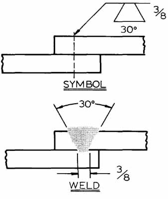
FIG. 19. How to identify a plug or slot weld.
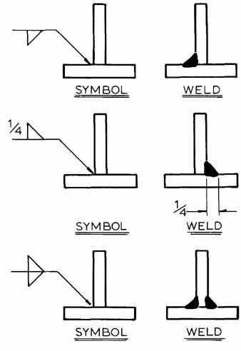
FIG. 20. How to indicate on which side or sides a weld is placed.
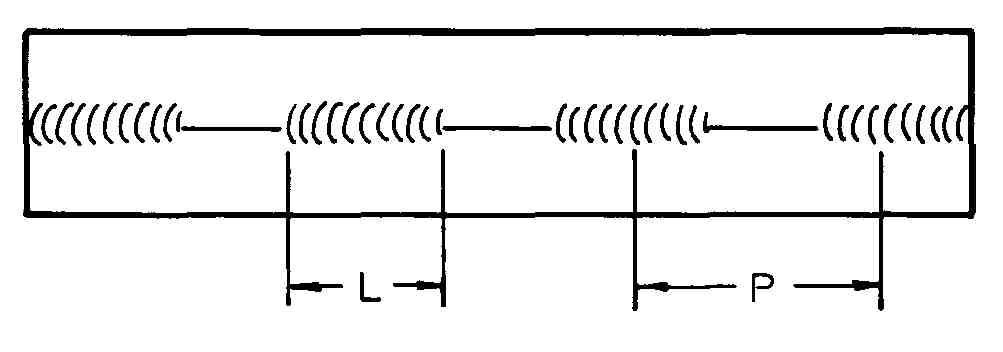
FIG. 21. What the length and pitch mean on a non- continuous weld.
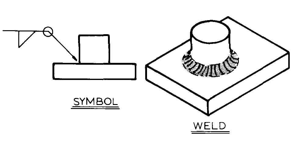
Fig. 22. Example of symbol to weld all around the joint.
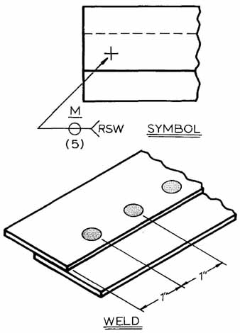
FIG. 23. Symbol means five spot welds located 1 in. apart and machined
flat.
WORKING WITH SHEET METAL
Electronics drafters design many sheet metal parts. The drafter must understand sheet metal and what happens to it when it is bent or formed.
Sheet metal parts are cut from flat stock using patterns or templates created by drafters. After pieces are cut out of the flat stock, they are usually formed by a BRAKE, FIG. 26. A brake will normally create straight lines and non-complex parts.
Complex parts will be made from metal blanks. The blanks will be punched or pressed over or into dies, FIG. 27. These parts will normally need to be trimmed after being formed. See FIGs. 28 and 29 for sheet metal drawings. FIG. 28 shows the part in a flat state. FIG. 29 shows the part after it has been developed.
FIG. 24. [coming soon] Symbols used to indicate the type of preparation and weld used in the joining process.
FIG. 25. A typical welding drawing.
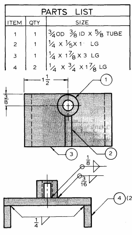
FIG. 26. A brake being used to form a sheet metal piece.
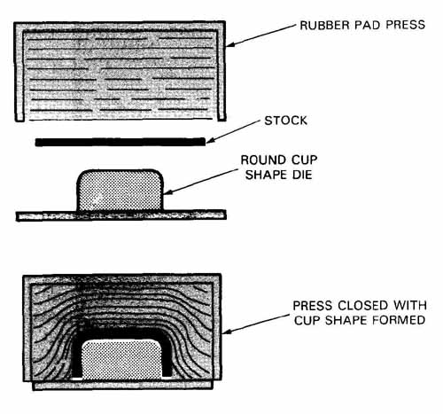
FIG. 27. A rubber pad is used to force the metal blank down smoothly
around the cup-shaped die.
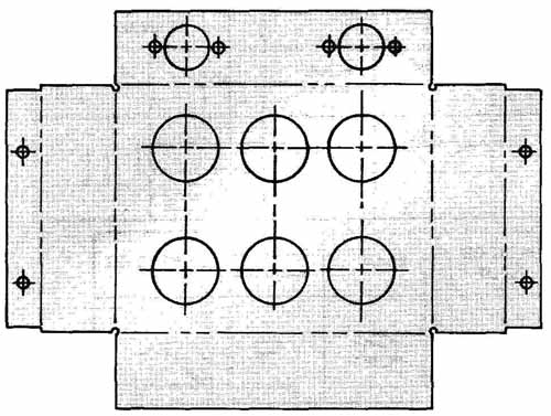
FIG. 28. A flat piece of sheet metal trimmed to size and punched with
appropriate holes.
BENDING SHEET METAL
When sheet metal is bent, there is a local thinning or thickening of the material. This is caused by the metal stretching on the outside of the bend and compressing on the inside. This causes plastic deformation of the material. Through studying many sheet metal parts, it has been found that there is a line through the bend where no stretching or compression takes place. This line is called the MEDIAN LINE, and the line is used for bend allowance calculations, FIG. 30.
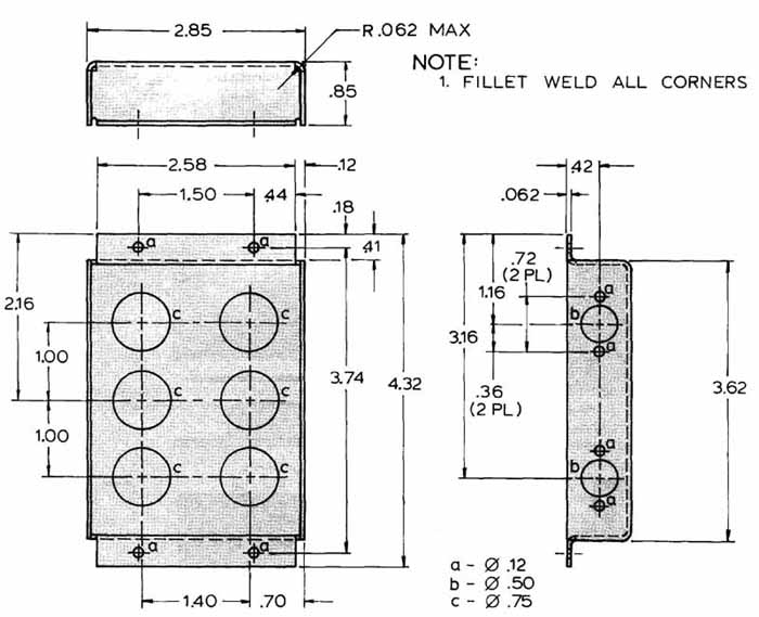
FIG. 29. The part shown in FIG. 28. It has been drawn as a developed
part with dimensions.
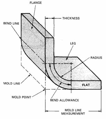
FIG. 30. Sheet metal terms and what they mean.
SHEET METAL TERMS
In order to fully understand the following information, you must first familiarize yourself with some basic terms:
Bend allowance: The length of material around a bend. Length is calculated on the median line, as indicated in FIG. 30.
Bend angle: The angle through which sheet metal is bent. The angle is measured on the outside of the bend. It is measured from the flat around the bend to the finished angle.
Bend line: The line formed by the beginning of the bend and the end of the bend. It is the tangent point on both intersections of the bend and flat surface.
Center line of bend: A radial line from the center of the bend radius and bisecting the included angle between bend lines.
Developed length: The length of a flat sheet which can be bent to create a part. This length is shorter than the sum of the mold line dimensions on the part.
Dimensioning and tolerancing: Dimensioning sheet metal parts formed on a brake is referred to the outside mold lines and inside bend radii. Dimensioning to inside mold lines will be done only if the inside finished dimensions are critical. If the inside dimensions are critical, the part should be produced by a die. Normally you will not tolerance brake-formed parts closer than ± .03 for bend radii or between bends. See FIG. 33.
Dimpling: Stretching a relatively small shallow indentation in the sheet metal. It can be used for countersinking for screw heads, FIG. 31.
Flat pattern: A flat layout of a sheet metal piece to be formed. The metal can be bent to make the finished part without trimming.
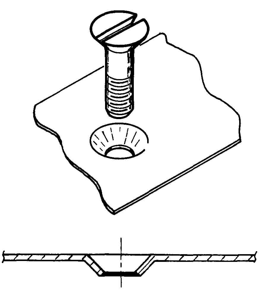
FIG. 31. A thin section of sheet metal dimpled to fit a screw head.
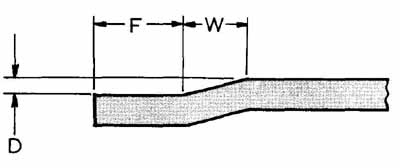
FIG. 32. A joggle shape with standard dimensioning technique.
Joggle: An offset in the sheet metal. It is used to give strength, design, or to set the edge for a mating part, FIG. 32.
Lightening holes: Holes or cutouts in sheet metal used to reduce weight. These holes are not functionally critical so they should be dimensioned for liberal sizes.
Mold line: The imaginary line of intersection of the two flat surfaces of the formed sheet metal part, as in FIG. 30.
Set-back: The amount of deduction in length of the flat pattern. This deduction is the saving in material by going around a bend radius rather than around a square or sharp corner. See FIG. 30.
CALCULATING BEND ALLOWANCE
To determine the distance around a bend, we must know three things. Find out the following:
1. The radius we will bend around. This will normally be determined by a bending table. See appendix.
2. Thickness of the material.
3. The angle of the bend.
If the radius is one inch or less, we can use this formula for bend allowance (BA):
BA = (.0078T + .01745R) x Degree of bend. I = Material Thickness = .125
R = Inside Bend Radius = R.25
To see how this applies, see FIG. 34. For the example in FIG. 34, BA equals 0.800.
BEND DIMENSIONING
Dimensioning of a bend will be done by establishing the mold point or mold line. To establish the mold lines, we can use trigonometry. The formula is:
X = (R + T)÷ (TAN-
X = distance from bend line to mold line
R = radius (inside)
I = thickness of material
a = included angle between flanges
TAN = TANGENT
Using FIG. 35, calculate the dimensioning
This number is used in the next calculation step.
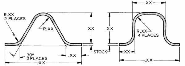
FIG. 33. Standard dimensioning techniques for sheet metal profile or
section views.
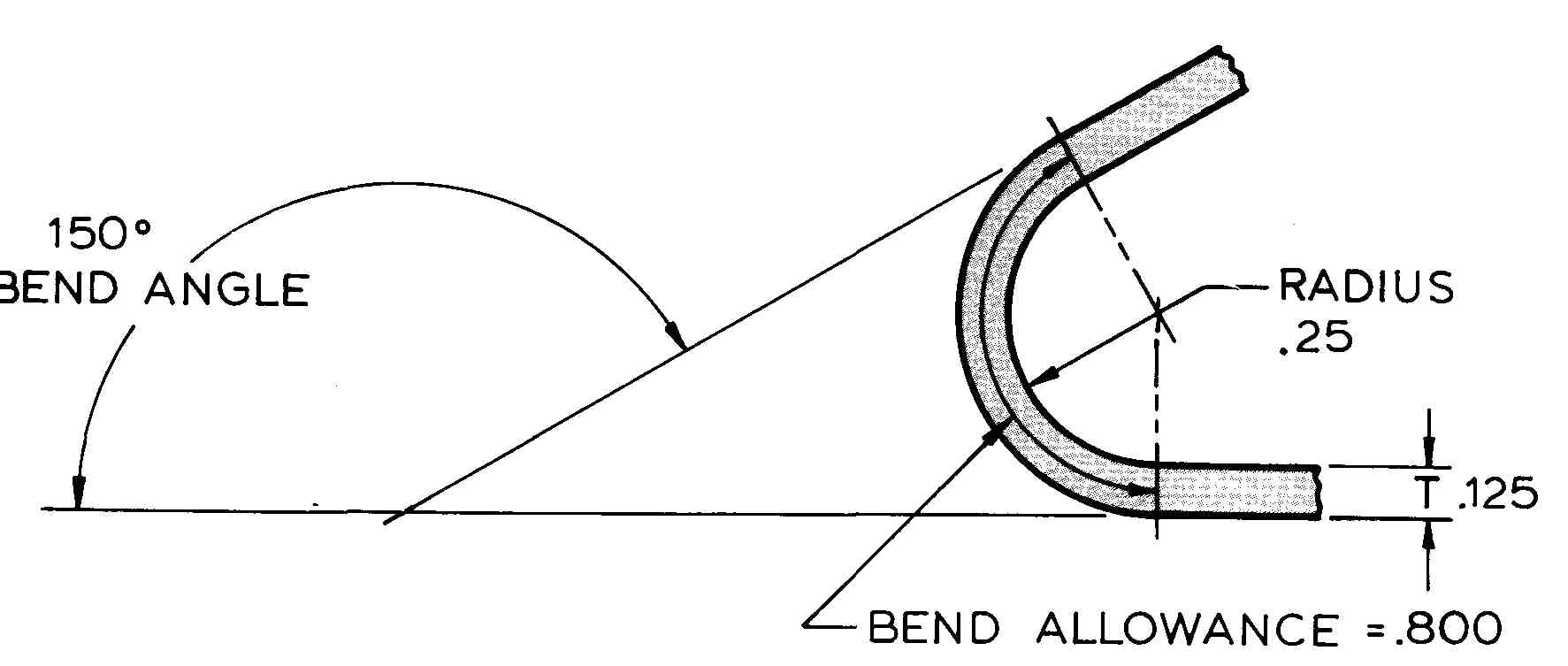
FIG. 34. Necessary information for figuring bend allowance. BA = 0.800
in this example.
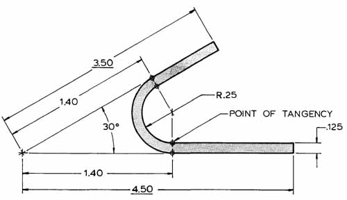
FIG. 35. Calculating the dimension from the bend line to the mold line.
It is the 1.40 dimension.
FIGURING SET-BACK FOR FLAT PATTERN
There is a formula to figure the deduction made in the length of a flat pattern. The deduction is equal to twice the distance from the bend line to the mold line minus the bend allowance. Look at the formula:
SET-BACK (K) = (2X—BA)
X = mold line to tangent point dimension
BA = bend allowance
Using the information from the previous two figures and this formula, you can design a flat pattern:
K=2(1.400)—.800
K = 2.800 — .800
K = 2.000
See FIG. 36 for the flat pattern drawing. With a perfectly sharp bend, the full length would be equal to 4.50 plus 3.50. But it is really 4.50 plus only 1 .50 because the set-back of 2.00 was subtracted.
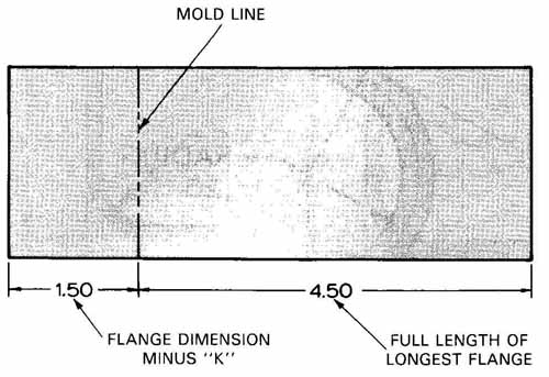
FIG. 36. A flat pattern dimensioned after figuring the set back distance.
The set-back, called “K,” equals 2.00.
CORNER BEND RELIEF
Whenever two sheet metal bends intersect one another, they require a corner relief cutout. Without this relief, the corner would buckle or wrinkle. Material must be removed .03 inches minimum behind bend lines, FIG. 37.
LIMITATIONS IN SHEET METAL
In order to bend a flange on a piece of sheet metal, we need a specific amount of material. Minimum widths are determined by material thickness and bend radius. Minimum distances between bends must also be allowed. A power brake can only work to set limits. The limits can be determined by adding the minimum flange width from the table in FIG. 38 to the bend radius plus material thickness.
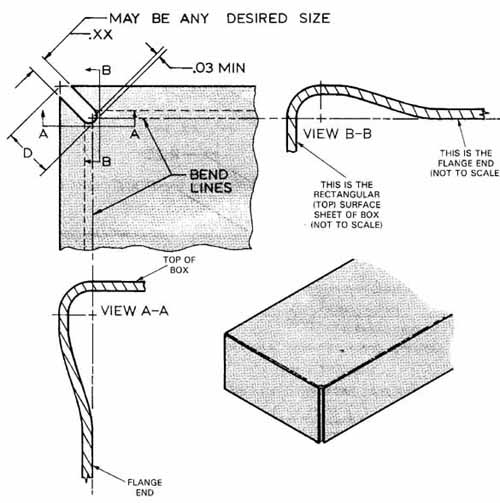
FIG. 37. Corner bend relief is required when two bends intersect. Here
the cup shape faces away from you.
FIG. 38. [coming soon] Use this table to figure minimum flange widths.
To calculate, use the following:
T (Thickness) = .051
R ( Bend Radius) = .25
W (Minimum) (From Table) = .55
L (Minimum Flange Length) FORMULA
L=W+R+T
L = .55 + .25 + .05
L = .85
The minimum flange length is .85 in this example. This means a bend can be no closer than .85 in. to any edge of the flat pattern. It also means bends can be no closer than 2L. Here, 2L equals 1 .70 in.
With this information, you can now consider dimensioning sheet metal drawings.
DIMENSIONING
Dimensioning skill is the main difference between drafters and designers. In order to be a designer, you must understand the form, fit, and function of the part or parts. With this understanding, you can dimension the part correctly. Poor dimensioning can add cost to a part whereas good practices will provide a quality part at low cost.
METHODS OF DIMENSIONING
The method you use may not be your main concern, but being sure that you convey the correct in formation to the machinist is important. FIG. 39 shows three dimensioning methods for dimensioning the same part. Each of these methods can control the part, but industry prefers the tabular method on complicated parts.
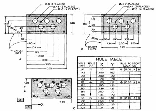
FIG. 39. Dimensioning methods. A—Coordinate dimensioning using the
bottom left corner as a datum. B—An example of a coordinate system where
one arrowhead is used on the dimension line. C—Tabular dimensioning.
The last column gives tolerance referred to surfaces A and B.
The tabular method requires less time because you do not have to figure where to place all the extension, dimension, and leader lines. It also sets up the part for numerically controlled machining. This part will be manufactured using the X-axis and Y axis as datum lines. Each one of the three methods shown uses the same datum corner. Datum selection should be based on the functional requirements of the part. Second, you should consider the manufacturing and inspection of the item. The datum must be easily recognizable and accessible so that all measurements from it can be easily made. Mating parts should use the same datum.
The above paragraphs may seem like the requirements for a mechanical drafter. They are requirements for both mechanical and electronics drafters.
Mechanical drafting knowledge is imperative for electronics drafters. Most of our electronics components will be housed in mechanical packages, or will be part of mechanical equipment. The number of electrical drawings in a project may be less than the mechanical drawings. In these instances, your employer will want good mechanical knowledge as well as electronics.
DIMENSIONING TERMS
You should become familiar with the following dimensioning terms:
Allowance: The amount of clearance or interference between mating parts. Example: a shaft in a wheel, with clearance, will turn freely. With interference, it will be pressed into the wheel, and they must turn together.
Tolerance: The amount a part’s dimensions can vary from the basic dimension.
Unilateral tolerance: The variation allowed in only one direction.
Example: .500 —.000 +.005
Bilateral tolerance: The tolerance variation allowed in both directions. Example: .500 ± .005
Limited dimension: The maximum and minimum sizes are specified. Example .505 .500
Fits: The tightness or looseness of mating parts. There are three general types of fits.
Clearance fits: Mating parts will always have a clearance (positive allowance).
Interference fits: Mating parts will always have interference (negative allowance).
Transition fits: A fit in which clearance or interference may occur.
DIMENSIONING RULES
The general rules for dimensioning are:
1. Each dimension must have a tolerance stated.
The tolerance can be with the dimension or stated in a general note.
2. No feature dimension should be repeated. If a dimension needs to be repeated, the second dimension must be referenced. An example is: (2.00).
3. Chain dimensioning should be avoided. It will cause a tolerance buildup. Use coordinate dimensioning. See FIG. 39A.
4. The finished part should be dimensioned without specifying manufacturing methods. An example would be the requirement for a 1 inch hole. If the finished hole measures 1 inch, you do not care if it was manufactured by laser beam, chemically etched, or drilled. However, engineering or manufacturing may request the process be specified.
5. Dimensions should be to visible outlines in pro file views. It is not good practice to dimension to hidden lines. You should not have to look at the adjoining views to interpret a dimension.
6. Dimensions should be placed outside the view.
7. Dimensions should be placed 1/2 in. or further away from object.
8. Parallel dimensions should be spaced a minimum of 3/8 in. apart.
9. Extension lines should start 1/16 in. away from object and continue 1/8 in. beyond the dimension line.
10. Arrowheads should be three times as long as they are wide.
11. Dimension, extension, and leader lines are all .01 wide.
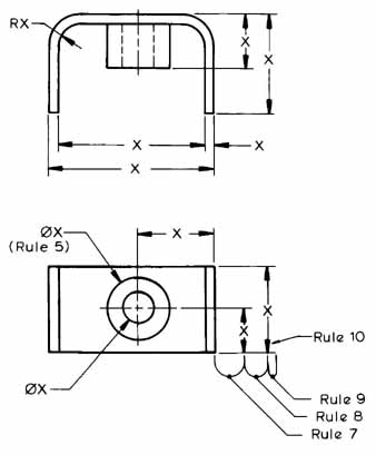
FIG. 40. An example of good dimensioning rules being applied.
FIG. 40 demonstrates some of the rules listed above.
ANGULAR DIMENSIONS
Angular dimensions are normally shown as in Fig. 41. The tolerance on most angular dimensions is plus or minus one degree.
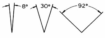
FIG. 41. Three examples of ways to dimension angles.
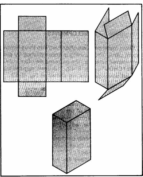
FIG. 42. An example of a developed stretchout being folded into a box.
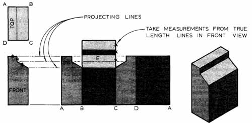
FIG. 43. Steps for developing a stretchout.
DEVELOPMENTS
Sheet metal parts are often bent into three dimensional parts. The bending is accomplished by pre determined patterns. The patterns are often called STRETCHOUTS, FIG. 42. The basic steps in laying out developments are shown in FIG. 43.
REVIEW QUESTIONS
1. Define the word packaging.
2. List four ways of permanently joining parts together.
3. What are the advantages of resistance welding?
4. List the commonly used mechanical fasteners.
5. What are the three main thread types for machine screws?
6. List the purposes for applying finishes to metals.
7. What three materials are most used in electronics packaging?
8. Compare thermosetting and thermoplastic plastics.
9. List the qualities of aluminum that make it good for electronics packaging.
10. If the inside sheet metal dimensions are critical, form the part with a __________
a. brake
b. power brake
c. die
d. wedge
11. What does the term “bend allowance” mean?
12. What is a lightening hole?
13. In order to be a designer, a drafter must understand the __________, , and __________ of the part or parts.
14. How do you select a datum for dimensioning?
15. Why is a knowledge of mechanical drafting important to the electronics drafter?
16. What is rule 5 in the dimensioning practices?
PROBLEMS
PROB. 1. Dimension FIG. 44 using coordinate dimensioning. Then dimension it using the tabular system.
PROB. 2. Figure the bend allowance for the bend shown in FIG. 45.
PROB. 3. Make a stretchout of FIG. 46. Figure the bend allowance using the following information: The material is .062 thick and is to be bent around a .12 radius.
PROB. 4. Add welding symbols to FIG. 47.
a. A 1/4 fillet weld.
b. A 3/1 6 fillet weld, all around.
c. A 1/4 fillet weld, opposite side.
d. A 1/4 fillet weld, all around.
e. A 1/4 fillet weld, all around, both sides.
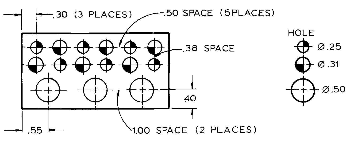
FIG. 44. Dimension the plate using coordinate dimensioning. Then dimension
it using the tabular system.
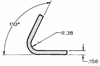
FIG. 45. Figure the bend allowance like that in FIG. 34.
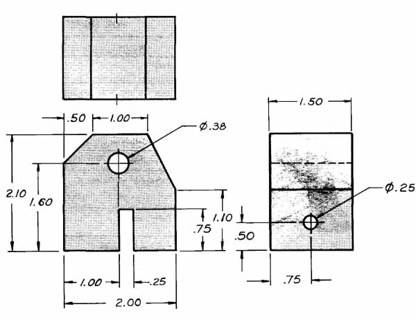
FIG. 46. Make a stretchout after finding the bend allowance.
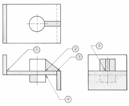
FIG. 47. Add fillet welding symbols as you alter the arrows.
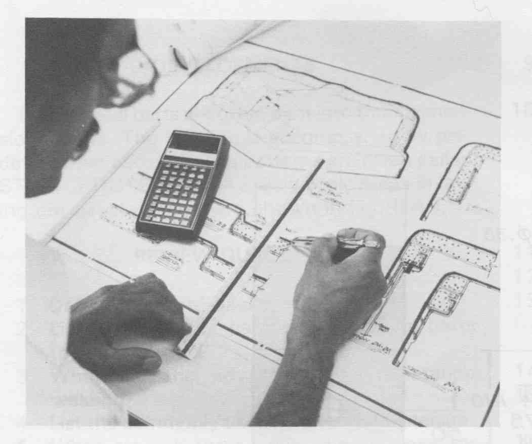
The mechanical engineer or design drafter may design plastic enclosure
prototypes. This work requires a knowledge of adhesives, resins, and
molding processes. (Owens-Corning Fiberglass Corp.)