AMAZON multi-meters discounts AMAZON oscilloscope discounts
A transformer consists of two or more inductors so wound that their magnetic fields interact. Usually the inductive coupling is maximized by winding the complete set of coils on a common closed magnetic core like a toroid (FIG. 1b) or the typical mains transformer core which consists of either a stack of E-I or C-T shaped soft iron laminations (FIG. 1a). Toroidal cores made from soft iron laminations are often used for mains transformers in equipment that is sensitive to stray magnetic fields, such as audio amplifiers. The windings are referred to as the primary (input) and secondary (output), respectively.
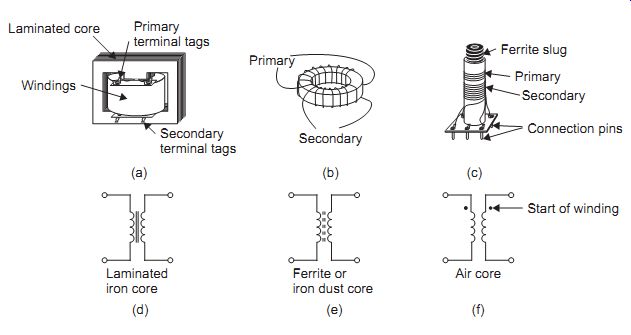
FIG. 1 Transformer types and symbols: Primary Secondary Ferrite slug Secondary
Connection pins (a) (b) (c) (d) (e) (f) Laminated iron core Laminated core
Ferrite or iron dust core Air core Start of winding Windings
For audio applications or low-frequency switch mode power supply units, the cores may be made of either silicon iron alloy or mu-metal. Mu-metal is an alloy that consists mainly of nickel, iron, copper, manganese and chromium.
For higher frequency applications, the core may be air, ferrite or powdered iron, also called iron dust.
Variable coupling between the primary and secondary of solenoid wound transformers (FIG. 1c) can be achieved by position of a ferrite 'slug', which may be adjusted to tune the circuits to resonance, so avoiding the need for a variable capacitor. Most of the modern power supply units that operate on the switched mode principle use transformers that are wound on ferrite cores, which may be toroid, E-I or enclosed bobbin cores (often called pot cores).
Some typical construction methods for transformers are illustrated in FIG. 1. Type (a) would be used for general-purpose mains and audio frequency work. A typical toroid for radio frequency (RF) use is shown in FIG. 1(b) and a variable solenoid typical of an intermediate-frequency transformer in a radio receiver in FIG. 1(c). The symbols used in circuit diagrams are shown in FIG. 1(d-f). The type of core is indicated by the lines between the windings, while no lines indicates an air core.
The construction of typical general-purpose mains transformers is shown in FIG. 2, the choice of lamination type E-I or C-T and the use of a split bobbin to separate the primary for the secondary being dependent on the exact application of the transformer.
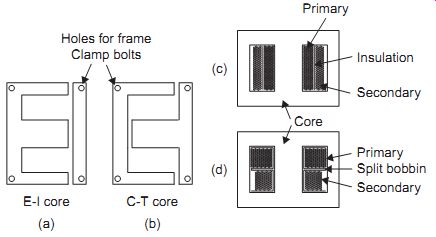
FIG. 2 Construction of typical mains transformers: (a) E-I and (b)
C-T core laminations, (c) secondary wound over primary, and (d) split bobbin
winding
The inputs may be provided either by the mains power system or by other signals, which may be either pure a.c. or varying level unidirectional currents. These are applied to the primary winding and induce output currents, which are always a.c., across the terminals of the secondary winding(s). Since the mutual magnetic induction depends entirely on a changing input voltage level, a steady d.c. input current in the primary winding would induce zero output signal in the secondary windings. Although a transformer primary can carry a direct current it is important that any direct current is not large enough to cause the magnetic field to saturate the core of the trans former, since this would reduce efficiency and introduce distortion in the output signal. Some transformers have a gap in the core to reduce the possibility of direct current in the primary (or secondary) causing the core to saturate. These gaps are very small (less than 0.5 mm) and may be found in C-T core audio transformers and pot cores for switch mode power supplies, etc.
When the current is taken from the secondary winding(s) by connecting a load, an increased primary current must flow to provide the power that is being dissipated. If no current is taken from the secondary winding, the residual current flow in the primary winding, described as the magnetizing current, will be very small.
The input and output signal voltages may be in-phase or antiphase, depending on the polarity of the secondary connections and the relative directions of the windings. The secondaries may consist of a single winding, multiple separate windings or a single winding with multiple voltage taps each designed to provide a particular level of output voltage. Some secondary windings may be centre tapped to provide balanced output voltages.
The ideal transformer
The ideal transformer would be one that has no loss of power when in use, so that no primary current at all would flow until a secondary current was being drawn. Large transformers come quite close to this ideal, which is used for basic transformer calculations. In an ideal transformer,
... where Vs ' _ secondary a.c. voltage, Vp ' _ primary a.c. voltage; ns _ number of turns of wire in the secondary winding, and np _ number of turns of wire in primary winding.
This last equation is often a convenient form which relates the signal currents in the perfect transformer to the number of turns in each of the two windings.
Transformer applications
Transformers are used in electrical circuits for the following purposes:
• voltage transformation: converting large signal voltages into low voltages, or vice versa, with practically no loss of power
• current transformation: converting low-current signals into high-current signals, or vice versa, with practically no loss of power
• impedance transformation: enabling signals from a high-impedance source to be coupled to a low impedance, or vice versa, with practically no loss of power through mismatch
• electrical isolation: for service purposes an isolating transformer, positioned between the mains supply and any equipment being worked on, will avoid electrical shocks to the operator.
Note that the transformer is a passive device without power gain. If a trans former has a voltage step-up of 10 times, it will also have a current step down of 10 times (assuming no losses en route).
Example:
The secondary winding of a transformer supplies 500 V at 1 A. What current is taken by the 250 V primary?
Solution:
Since V' p _ I' p _ V' s _ I' s, then 250 _ I' p _ 500 _ I' s, so that I' p _ 2 A.
Transformers may also be used as matching devices so that the maximum power can be transferred from one circuit to another. The ideal method of delivering power to a load would be to use amplifiers that have a very low internal resistance, so that most of the power (I^2 R) was dissipated in the load. Many audio amplifiers make use of such transistors to drive 8 ohm loudspeaker loads. For some purposes, however, transistors that have higher resistance must be used or loads that have very low resistance must be driven, and a transformer must be used to match the differing impedances.
In public address systems, for example, where loudspeakers are placed at considerable distances from the amplifier, it is normal to use 100 V line signals at low currents so as to avoid I^2 R losses in the network. In such cases the loudspeakers are coupled to the lines through transformers.
From the voltage, current and turns ratios described above, we can deduce that the input and output load resistance values have the following ...
... secondary winding. The equivalent circuit for a perfect transformer is there fore that shown in FIG. 3.
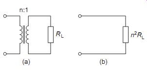
FIG. 3 Equivalent circuit: (a) perfect transformer with load resistor,
and (b) equivalent load resistor.
For the maximum transfer of power, from an amplifier with output impedance Z_OUT to a load with resistance R_L the turns ratio n _ np/ns can be expressed in the following way:
Example:
A power amplifier stage operates with a 64 ohm output impedance. What transformer ratio is needed for maximum power transfer to an 8 ohm load?
Solution:
A 3:1 step-down transformer could therefore be used off the shelf, or a transformer specially wound for a 2.8:1 ( 8 ) ratio.
===
EXPERIMENT 1
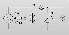
FIG. 4 Circuit for Practical 1 Set up the circuit shown in FIG. 4. Use
a small mains transformer, like a 12 V or 18 V output type and a 1 kO
2 W variable resistor or similar as the variable load resistor. Measure
the load voltage and load current for different settings of the variable
load resistor, and plot a graph of load power (P _ V.I ) on the y-axis
against load current on the x-axis. What can you deduce from the graph
about the trans former ratio? Try swapping the primary and secondary connections
and repeating the experiment. Explain the difference in the graph.
What resistor settings give peak power transfer?
===
Transformer power ratings
Owing to the nature of the self-inductance and capacitance of the transformer and the effects of the load, the a.c. voltage and current in the secondary circuit are rarely in phase. The power loading measured in watts can therefore be misleading and a more meaningful assessment uses the term volt amps (VA). Furthermore, the rising voltage drop that occurs as the load current increases is described by the regulation factor. Typically, in small to medium-sized equipment power units, this accounts for losses of about 10%.
Consider the calculations associated with the following transformer designed to provide a secondary supply of 12 V at 4 A or 48 VA. This would produce an output of 12 V when driving a 48 W load. As the load is reduced, the voltage will rise owing to the regulation factor by about 10% to 13.2 V. (Note that this is not the same as the d.c. output after rectification).
Using a typical value of 4.8 turns per volt plus an extra 1% for each 10 VA of loading produces 12 _ [4.8 _(1% of 4.8)] or approximately 60 secondary turns. Looking up wire tables would show that this loading could be safely supported by 1.25 mm diameter wire.
For the 250 V primary winding at 60 turns/12 V (or 5 turns/volt), this will require 250 _ 5 _ 1250 turns.
Maximum power transfer
If a generator and load are both resistive (V and I in phase), then the maximum transfer of power occurs when the internal generator resistance (RG) and load resistance (RL) are equal (i.e. when RG _ RL). Matching of these values can be achieved using a transformer.
When the impedance of a generator or load has a reactive component (so that V and I are not in phase), maximum transfer of power occurs when the magnitudes of the impedances are equal, but with equal and opposite phase angles, i.e. when Z(F) _ Z(-F), where Z is the magnitude of the impedances and F is the phase angle. By using equal and opposite phase angles, the two parts of the circuit are brought into resonance to ensure the maximum transfer of power. This result explains why some industrial mains power inputs incorporate power factor correction capacitors.
Transformer losses
The three main types of power loss that occur in a transformer are:
• I^2 R losses caused by the resistance of the windings
• eddy-current and stray inductance losses caused by unwanted magnetic interactions
• hysteresis loss arising from the core material (if a core is used).
Taking these in turn, I^2 R (or joule) losses are those that are always incurred in any circuit when a current, steady or a.c., flows through a resistance.
These losses can be reduced in a transformer by making the resistance of each winding as low as possible, consistent with the correct number of turns and the size of the transformer.
Joule losses are generally insignificant in small transformers used at radio frequencies, but they will cause overheating of mains transformers, particularly if more than the rated current is drawn or if ventilation is inadequate.
Stray inductance and eddy-current losses are often more serious. An ideal transformer would be constructed so that all the magnetic field of the primary circuit coupled perfectly into the secondary winding. Only toroidal (ring-shaped) transformers come close to this ideal. In practice, the primary winding generates a strong alternating field which is detectable at some distance from the transformer, causing a loss of energy by what is termed stray inductance.
In addition, the alternating field of the primary can cause stray voltages to be induced in any conducting material used in the core or casing of the transformer, so that unwanted currents, called eddy currents, flow. Since additional primary current must flow to sustain these eddy currents, they cause a loss of power, which can be significant.
The problem of eddy currents in the core is tackled in two ways:
• The core is constructed of thin laminations clamped together, with an insulating film coating on each to lessen or eliminate conductivity.
• The core is constructed from a material that has high resistivity, such as ferrite.
The third type of loss, called hysteresis loss, occurs only when a magnetic core is used. It represents the quantity of energy that is lost when a material is magnetized and demagnetized. This type of loss can be minimized only by careful choice of the core size and material for any particular transformer.
Hysteresis losses will, however, increase greatly if the magnetic proper ties of the core material change, or if the material becomes magnetically saturated. The following precautions should therefore be taken in connection with transformers:
• Do not dismantle transformer cores unnecessarily, or loosen their clamping screws.
• Never bring strong magnets near to a transformer core.
• Never pass d.c. through a transformer winding unless the rated value of the d.c. is known and is checked to be correct.
Types of transformer
Mains supply
===
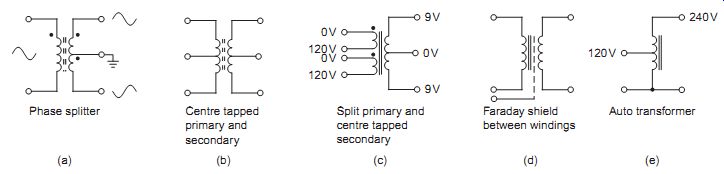
FIG. 5 Types of transformer winding: (a) phase splitter, (b) centre
tapped windings, (c) split primary mains transformer, (d) Faraday shield
to minimize capacitive coupling between windings, and (e) step-up autotransformer
===
Mains frequency is low and fixed at either 50 or 60 Hz. A substantial core is required which must be laminated (hysteresis losses can be reduced to negligible proportions by careful choice of a core material). Where an external magnetic field is especially undesirable (as in audio amplifiers and cathode ray oscilloscopes), a toroidal core can be used with advantage.
FIG. 5(c) shows a mains-type transformer with split primary windings. This set-up allows the transformer to be switched from 230 V input, using the two windings connected in series, to 120 V operation, using the two windings connected in parallel. Many items of equipment that have a mains selector switch to switch from 120 V to 240 V input use this type of transformer. Industrial equipment that is manufactured for both the US and European market often uses just one type of transformer, with the links being hardwired at assembly time and replacement power supply units often being shipped un-configured. The increasing use of universal input switch mode power supplies has made this much less common than it was.
Audio frequency
The core material must be chosen from materials causing only low hysteresis loss because of the higher frequencies that will be encountered. The windings must be arranged so that stray capacitance between turns is minimized. In general, any flow of d.c. is undesirable.
Medium- to high-frequency RF and VHF
In this range, the losses from laminated cores are unacceptably high, so that iron dust, ferrite or air cores must be used. Because of the high frequencies involved, a small number of turns is sufficient for each winding. Stray fields are difficult to control, so that screening (see below) is often needed.
UHF and microwave
Only air cores and specialized ferrite materials can be used in this range, and 'coils' may actually consist of less than one full turn of wire. They may even consist of short lengths of parallel wire. Unwanted coupling becomes a major problem, so that the physical layout of components near the trans former assumes great importance.
Standard windings
FIG. 5(a) shows how a transformer with a center tapped secondary may be used to provide antiphase outputs, such as required for driving power output stages of linear amplifiers or for full wave rectification purposes.
The autotransformer is a single-tapped winding, shared by both input and output, equivalent to the use of a double-wound transformer with a common primary and secondary terminal. The ratio of input/output voltages and currents still follows the normal transformer relationships. An autotransformer with a variable tapping position (such as the Variac) is used for providing variable voltage a.c. supplies. Note, however, that such trans formers provide no isolation between their primary and secondary windings (FIG. 5e).
Bifilar winding, twisting the primary and secondary wire together before winding them onto the core, is a method of providing very close coupling between primary and secondary windings, it is particularly useful in audio and radio frequency transformers. If a tapped primary or secondary is required then this method of construction can be extended to three or more cores (trifilar, etc.). Because the primary and the secondary turns are wound together, rather than in separate layers, there is significant interwinding capacitance.
Components such as printed circuit board tracks, wiring and inductors may need to be shielded from the magnetic field created by transformers. This is difficult; it is much better to use a core design that minimizes the external field, such as the toroid.
Electromagnetic screening requires the use of high-permeability alloys such as mu-metal or super-permalloy to encase the device to be protected.
Boxing a component in such a way ensures that any magnetic fields are contained within the casing, preventing the fields from entering the enclosed space.
Electrostatic screening is comparatively easy, since any earthed metal between a component and the transformer will screen the component from the electrostatic field of a transformer. When interaction between windings needs to be prevented a Faraday shield is placed between the windings, usually consisting of a copper foil strip the width of the winding on the transformer. This must be insulated so that it does not make a complete conducting turn around the core, since this would be a shorted turn, causing the output of the secondary to be greatly reduced and a very high current to flow in the primary, possibly leading to overheating and failure (FIG. 5d).
===
Using a transformer of known turns ratio, preferably a type using a tapped secondary winding, connect the circuit of FIG. 6. An effective component to use in this experiment is a toroidal core with a 240 V primary winding, obtainable from most educational suppliers. Measure the a.c. input and output voltages for each set of taps, and find the values of Vs/Vp. Compare these values with the known values of the turns ratio. The secondary load resistor is optional, but if used should be around 1 kO and helps by ensuring that some secondary current flows.
EXPERIMENT 2
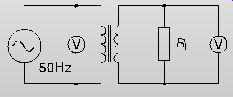
FIG. 6 Arrangement for Exp .2
==
The following are common transformer faults, with hints on how to detect and remedy them:
• Open-circuit windings can be detected by ohmmeter tests. A winding may also acquire high resistance, which is caused by high-resistance internal connections, typically 100 K instead of 100 ohms.
• Short-circuit turns: these are difficult to detect because the change of resistance is very small. Even a single turn that is short-circuited will dissipated considerable energy while making practically no difference to the d.c. resistance, making it very difficult to locate. Shorted turns will cause an abnormally large primary current to flow even when the secondary is disconnected, so that mains transformers overheat and transformers operating at high frequencies fail completely. This is a fault that particularly affects television line output transformers. The simplest test and cure is replacement by a component known to be good.
• Loose, damaged or missing cores: loose cores will cause mains trans formers to buzz and overheat. Cracked or absent ferrite cores in radio frequency transformers will cause mistuning of the stage in which the fault occurs.
Thermal protection of transformers
Power supply circuits almost invariably contain protection devices, to provide overvoltage and overcurrent protection for the equipment being powered.
Supplies and transformers also require protection and there are also the requirements of product safety, to prevent overload or fault conditions resulting in fire or electric shock hazard to the user.
Fuses
Fuses or fuse links are the most commonly used safety critical device for protection against overload conditions, but they are also open to misuse.
The fuse link should always be replaced with one of the correct rating after the fault condition has been cleared.
The fuse-link rating is the current that the device will carry for a long period. It will often carry a current that is 25% in excess of the rated value for 1 h or more. A further parameter is the joule rating, which is given by I 2 t, showing that the failure depends on the square of the current and the time for which it is flowing. The minimum fusing current is typically 50- 100% above the rated value. Hence, many fuse links are described as slow blow devices.
Fuse links usually have a voltage rating that is different for a.c. and d.c. applications.
Embedded devices
These devices are often buried within the winding space of a trans former and wired in series with the primary winding. When the current exceeds some value the temperature of the transformer rises, increasing the resistance of the thermistor so that the input current falls to lower the temperature.
An embedded bimetallic operated switch with its contact wired in series with the primary current has been used in the past. The switch contacts open when the transformer temperature rises above some predetermined level to provide protection. When the temperature falls this system is self-resetting.
Another embedded protection device found in low-cost transformers such as those used in mobile phone chargers consists of a conducting spring strip soldered at one end to a contact with low melting-point solder. If the temperature exceeds the melting point of the solder the strip springs away from the contact, breaking the circuit. These devices cannot usually be reset.
Note: for all resettable embedded devices, a continuous cyclic switching action indicates a fault in urgent need of attention.
QUIZ:
Q_1. A step-down transformer uses a 9:1 ratio. If the primary voltage is 240 V a.c., what (assuming no losses) is the secondary output?
(a) 53.3 V
(b) 36 V
(c) 26.7 V
(d) 25 V.
Q_2. A transformer operates from 240 V mains and delivers an output of 60 W at 6 V. Assuming no losses, what amount of primary current flows?
(a) 0.1 A
(b) 0.25 A
(c) 2.5 A
(d) 10 A.
Q_3. A transformer is to be used to match a source resistance of 100 ohms to a loudspeaker of 4 ohms. What ratio is needed?
(a) 25:1
(b) 16:1
(c) 5:1
(d) 4:1.
Q_4. A 470 O resistor is connected across the secondary of an ideal transformer with a 20:1 turns ratio and the primary is connected to the mains supply at 230 V r.m.s. How much power is dissipated in the resistor?
(a) 127 mW
(b) 281 mW
(c) 489 mW
(d) 5.63 W
Q_5. A transformer with a pre-wound primary is required to provide a low-current 33 V output. If the mains input is 230 V and the primary winding has 1000 turns, how many secondary turns are needed?
(a) 121
(b) 143
(c) 182
(d) 286