AMAZON multi-meters discounts AMAZON oscilloscope discounts
General fault-finding methods
Fault-finding for electronic/electrical equipment is a skill that is neither an art nor a science, but an engineering discipline in its own right. Effective fault-finding requires:
• a good general knowledge of electricity and electronics.
• specialized knowledge of the faulty equipment.
• suitable test equipment.
• experience in using such test equipment.
• the ability to formulate a procedure for isolating a fault.
• the availability of service sheets and other guides.
A good general knowledge of electricity/electronics is essential because not all equipment is well documented, and in some cases only a circuit diagram (or even nothing at all) may be available as a guide. Failing a concise description of how the equipment works, you may have to work out for yourself the progress of a signal through the equipment. In addition, a wide general knowledge is needed if you are to make reasonable assumptions about how to substitute components. You are not likely to know why something does not work if you do not know what does make it work.
Specialized knowledge can greatly reduce the time spent in servicing, and if your servicing is confined to a few models of equipment you are likely to know common or recurring faults by their symptoms. All too often, how ever, service engineers are likely to have to struggle with unfamiliar equipment for a large portion of their time, and the services that are now available on the Internet allow you to plug into the experience of others.
Suitable test equipment is essential. The days when a service engineer could function effectively with little more than an multimeter and a screw driver are long gone, and although the multimeter is still an important tool (as also is the screwdriver) the service engineer needs at least one good general-purpose oscilloscope, along with signal generators, pulse generators and more specialized equipment appropriate for the type of equipment being worked on.
Experience in using test equipment is also essential. All test instruments have limitations, and you must know what these are and how you can avoid being hung up by these limitations. You must know which tests are appropriate for the faulty equipment, and what the result of such tests would be on equipment that was not faulty.
The ability to formulate a procedure for isolating a fault means that you need to know what to test. All electrical and electronic equipment consists of sections, and much modern electronics equipment uses a single integrated circuit (IC) per section. You should be able to pin down a fault to one section in a logical way, so that you do not waste time in performing tests on parts of the circuit which could not possibly cause the fault.
An important point about all fault-finding is that you should make note of all the tests you have applied and the results of these tests. Without this, you are likely to forget what you have done, and end up taking measurements haphazardly, making diagnosis impossible.
Do not forget the simple things. We tend to make fun of the customer who has forgotten to check whether the mains switch was on, but we can be guilty of similar neglect ourselves. In particular, always check plugs and connectors for any equipment that is not functioning. The next logical check is that power supplies are present within the equipment. Once these elementary checks have been made, we can start looking for more serious faults.
The classical method of isolating a fault has, in the past, been to check signal inputs and outputs for each stage, but this is no longer the only method that needs to be used, and in some cases, the use of feedback loops, limiters and other interacting circuits makes it much more difficult to find where a fault lies. Once again, experience is a valuable guide.
The availability of service sheets and other guides is also important.
Much commercial equipment consists of components that carry only factory codes, and whose actions you can only guess at in the absence of detailed information. In addition, good service sheets will often carry a list of known recurring faults, and will also give valuable hints on fault-finding methods.
Basic fault-finding in both analog and digital systems follows principles that are similar. A source is required to inject suitable signals into the input and the signal processing is then monitored as it passes through the system on a stage-by-stage basis. For analog systems a suitable input source is a signal generator, while an oscilloscope can be used as a monitor. For digital systems this end-to-end technique can be carried out using a logic pulser to provide the inputs while the processing can be monitored with a logic probe. You can use this method in either direction, input-to output or output-to-input.
Another technique that is often used with advantage to speed up diagnosis is known as the half-split method (or divide and conquer). Here, the system is divided into two sections and the end-to-end technique used to find the faulty half. Once this is found, this part is again divided into two, and the check repeated. This process is then repeated continually until the faulty stage is identified. It is unusual to require more than three repetitions of this method.
Finding a fault is not, unfortunately, a certain step towards repair. Some equipment carries ICs which are no longer in production and for which no replacement is available. Many firms, particularly manufacturers of domestic electronic equipment, will provide spares and help for only a limited period, and some firms seem to deny all responsibility for what their equipment does after a few years. Given the comparatively long life of most electronic equipment, it would be unreasonable to expect spares to be available indefinitely, but it is not easy to tell a customer that the television receiver bought only 6 years earlier cannot now be serviced because it contains parts for which these is no current equivalent. Manufacturers may like to remember that customers tend to have long memories about such things: it certainly affects my judgment when I want to buy anything new.
Servicing digital systems
In some respects, servicing logic circuitry can be simpler than working on analog circuits of comparable size. All digital signals are voltages at one of two levels, and there is no problem of identifying minor changes of waveshape which can so often cause trouble in linear circuits. In addition, the specifications that have to be met by a microprocessor circuit can be expressed in less ambiguous terms than those that have to be used for analog circuits. You do not, for example, have to worry about harmonic distortion or intermodulation, and parasitic oscillation is rare, although certainly not impossible.
That said, logic and microprocessor circuits bring their own particular headaches, the worst of which are the relative timing of voltage changes and the difficulty of displaying signals. The actions of any microprocessor circuit depend on strict timing of many pulses being maintained, and conventional equipment which serves well for the analysis of analog circuits is of little use in working with microprocessor circuits. The problem is compounded by the fast clock rates that have to be used for many types of microprocessor.
You may, for example, be looking for a coincidence of two pulses with a 66 MHz clock pulse, with the problem that the coinciding pulses happen only when a particular action is taking place. This action may be completely masked by many others on the same lines, and it is in this respect that the conventional oscilloscope is least useful. Oscilloscopes as used in analog circuits are intended to display repetitive waveforms, and are not particularly useful for displaying a waveform which once in 300 cycles shows a different pattern. A fast conventional oscilloscope is useful for checking clock pulse rise and fall times, and for a few other measurements, but for anything that involves bus actions a good storage oscilloscope is needed.
Software and hardware, such as that provided by Pico Technology, can be used along with a fast modern personal computer (PC) to provide facilities for logic circuit diagnosis (see Section 31).
In addition, some more specialized equipment will be necessary if any thing other than fairly simple work is to be contemplated. Most of this work is likely to be on machine control circuits and the larger types of computer.
Small computers do not offer sufficient profit margin in repair work to justify much diagnostic equipment. After all, there is not much point in carrying out a $400 repair on a machine that is being discounted in the shops to $500! We shall start this section looking at some typical fault conditions, and then at specialized instruments for digital circuit work.
EXPERIMENT 1: Use suitable test equipment to locate faults in remote controls, A-D and D-A conversion circuits, and seven-segment displays.
Common problems
Some of the problems that occur in digital equipment are due to poor servicing or poor manufacturing techniques, while others may be brought about by failure of associated equipment (such as a regulated power supply). In this section we shall concentrate on common causes of failure of ICs. These are:
• incorrect insertion into sockets
• pins shorted during measurements
• poor soldering techniques
• insertion/removal with power applied
• incorrect voltage levels
• input pins left disconnected
• electrostatic discharge.
Incorrect integrated circuit insertion
Incorrect insertion into a socket is most likely for the larger dual in line (DIL) ICs, and the most common error is that pin 1 of the IC has been put into the pin 3 position of the socket, or pin 3 of the IC has been put into the pin 1 position of the socket. Since the V_ and earth pins are usually located at opposite corners of a chip, incorrect insertion will almost certainly make one of these connections open-circuit. The older Schottky transistor- transistor logic (STTL) chips (and many of the LS types) will survive having power switched on in these circumstances, but metal oxide semiconductor (MOS) chips are more vulnerable. Always be prepared to test and, if necessary, replace a chip that has been incorrectly inserted.
Live measurements
Making measurements of voltages on a (live) working chip is reasonably simple for chips of the 74 family type, provided the correct tools are used. By far the best method is to slip an adapter over the chip. These are made for the most popular pin layouts, and they provide a set of contacts on the top cover that correspond to the IC pins and are electrically connected through clips.
These contacts are well away from the printed circuit board (PCB) surface, and you can make clip connections to them without any risk of short-circuits.
Without such adapters, great care has to be taken over pin voltage measurements, particularly the voltage difference between pins. Absolute voltage readings can be taken by clipping one lead of the meter to an earth point, and using a probe held to the IC pin. The probe should be insulated almost to the contact point to prevent shorting between pins.
By far the worst measuring problems relate to closely spaced pins, particularly the square layouts used on microprocessors and application-specific integrated circuits (ASICs). Adapters are available from the manufacturers for some types, but the only alternative is to use a fine probe with insulation almost to the tip.
Poor soldering
Poor soldering is a problem that is not quite so common now that manufacturing techniques have improved, but it is still a source of faults. The nature of modern boards with very fine tracks, small solder-pads and surface mounted (SM) components requires excellent soldering systems, and poses a problem for fault-finding because a badly soldered joint is very difficult to detect by eye.
Another, more recent, problem is that the use of modern lead-free solders seems to have caused a rise in the incidence of dry joints.
A good magnifying glass and a bright light can help, but if you are convinced that the problem is in an area that appears to be all right, the usual treatment is to apply a soldering iron to see whether this clears up the problem. The iron should be fitted with a very small bit, and it often helps to give the suspect area a thin coating of an approved flux paint. Needless to say, the equipment must be switched off and time allowed for capacitors to discharge before any such resoldering is attempted.
Another aspect of this problem is a poorly soldered repair. Even with care, some repairs on modern PCBs are very difficult, particularly with SM components, and soldering must be suspected if a circuit fails to operate correctly after a repair (involving soldering) has been carried out.
Power off
We tend to take it for granted that power will be off when any repair is being done, but there is a temptation to remove and insert chips with power still on. This is something that must be resisted, even if switching off and on is not a straightforward action (as for many computer boards). Not only must the power be off when any chip is removed or replaced, it must have been off for long enough for capacitors to have discharged.
Remember that some PCBs may contain backup batteries, and these may have to be temporarily removed for some repairs. Since the backup batteries are there to keep memory working, this will require a considerable amount of work after restoring the battery, and you should consult the manufacturer's recommendation on this subject.
If you need to replace a battery on a PC motherboard, you may be able to connect an external battery to maintain the memory while the internal cell (nowadays often a lithium-ion type) is replaced. If not, motherboards usually provide for a set of defaults to come into use after the backup battery power has been interrupted.
Incorrect voltage levels
Incorrect voltage levels can arise in several ways. One is the incorrect connection of cables that carry power from a power supply unit (PSU) to a board, and another is the failure of regulation of a power supply. Incorrect cable connection is unlikely on units such as modern PCs (using the ATX motherboard system), but if there is any doubt, the alignment of the connectors should be marked before they are separated.
Failure of regulation is a problem that is less easily avoided. Some circuit boards are surprisingly immune to regulation failure, particularly when no signals are applied, but for complex circuits, the PSU should incorporate overvoltage protection systems.
Any work that is done on the PSU should preferably be done with the unit separated, and then with a dummy load connected for testing. In this way, any faults that cause incorrect voltage outputs will not damage ICs on the main boards.
Disconnected inputs
Input pin disconnections can arise from the incorrect insertion of ICs into sockets or from incorrect soldering of ICs to a board. They cause little harm on STTL circuits, where a disconnected input will float high, but can cause damage on MOS ICs when power is applied. Modern circuit boards are designed so that a path to earth is available on any input, but only if the IC pins are connected to their tracks.
===
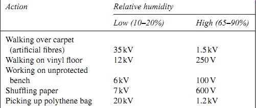
Table 1 Electrostatic voltages in the workshop Action Relative humidity
Low (10-20%) High (65-90%) Walking over carpet (artificial fibers) 35 kV 1.5 kV
Walking on vinyl floor 12 kV 250 V Working on unprotected
bench 6 kV 100 V Shuffling paper 7 kV 600 V Picking up polythene bag 20 kV 1.2 kV
===
Electrostatic discharge
Electrostatic discharge (ESD) should never be a problem for any IC that is correctly connected into circuit on a board, because the board will provide discharge paths. Damage is more likely when ICs are handled before insertion in a board, because the only protection available is by way of diodes incorporated into the chips, and these offer only limited protection.
The comparatively high humidity of the climate in the UK allows us to get away with working practices that would cause electrostatic dam age elsewhere, and it is quite common even in manufacturing to see MOS devices being handled without elaborate electrostatic precautions. This is not, however, good practice, and the basic precautions of working in a well earthed environment and keeping one hand earthed should be observed.
The worst hazards are the ever-present plastic bags and other plastic packaging materials, all of which are electrostatic hazards. Computer components are always packed in conductive plastic (brown or black), and a collection of these materials can be useful to provide a clean conducting surface for placing sensitive ICs.
Electrostatic damage, see also (Sections 19 [Level-2 Book] and 28) is most likely to affect metal oxide semiconductor field-effect transistors (MOSFETs), some of which can be damaged by a voltage as low as 35 V. Damage to a simple transistor is likely to cause failure, but damage to elaborate MOS ICs may be less obvious, causing reduced performance and/or shortened life. Table 39.1 indicates the level of electrostatic voltages that can be generated under typical conditions. Note that even bipolar devices and diodes can be damaged by less than 3 kV levels, although the amount of current that can pass is often too low to cause lasting damage.
The figures for high relative humidity apply fairly generally in the UK, where the workshop is naturally ventilated, but the lower figures are more likely where air-conditioning is used.
Damage to MOS ICs is possible whenever an electrostatic voltage can be applied to a pin or set of pins and can cause current to flow to grounded pins. This is most likely if an IC is incorrectly inserted or soldered so that some pins are earthed and one or more is unconnected.
Device sensitivity
The devices that are most sensitive to electrostatic damage are MOS and complementary metal-oxide semiconductor (CMOS) chips that have no internal protection circuits, and discrete MOSFETs that also have no discharge paths built in. These devices are very rare now, but if they are present the utmost caution should be exercised in handling the devices, observing all the precautions recommended by the manufacturers.
Less sensitive devices include 74LS chips, analog ICs, r.f. transistors for 500 MHz or more, semiconductors that incorporate silicon dioxide insulation, and MOS/CMOS devices with diode protection for inputs, along with junction field-effect transistors (JFETs) and precision thin-film resistors. The least sensitive devices include microcircuits, small-signal transistors (less than 10 W output) and thick film resistors.
To put all this into perspective, I have never had a chip damaged by ESD in 45 years of handling components. Damage to items such as low noise block (LNB) circuits is more likely to be caused by electrical storms.
Some of the protective measures that are normally used to prevent ESD damage are noted here.
• Before starting any servicing work, check technical manuals and any leaflets for warnings and instructions regarding electrostatic damage precautions.
Ensure that the working environment is as free as possible from electro static hazards, and try to ensure that nothing you do will generate high electrostatic voltages (e.g. shuffling your feet on a carpet or on vinyl tiles).
• Before servicing equipment, you should earth yourself. The simplest way is to touch an earthed metal object, but if you have acquired a substantial amount of charge this can be painful. A better method is to provide in the workshop an earthed rail or wire to which 1 M resistors are connected at intervals, with a small metal ball soldered to the free end of each resistor. Touching one of these metal balls will earth you painlessly without sparks.
• In low-humidity conditions it is much more satisfactory to wear an earthing strap, a metal strap that is permanently connected (usually through a 1M resistor) to earth.
Safety regulations demand that you should not use any mains operated equipment while you are wearing an earthing strap.
The most risky procedures involve the unpacking of new devices.
Handling must be kept to a minimum, with attention to earthing at all times, and you should try to ensure that the workshop environment is maintained so that materials that cause high electrostatic voltages are kept to a minimum. Do not unpack sensitive devices until you are ready to use them.
The conductive packing plastic that is used for sensitive devices can be used to hold the chips while you insert them, but if this is not possible, hold ICs by the body corners only, avoiding any contact with the pins. Avoid in particular any contact between IC pins and any clothing or (non-conducting) plastic. If you are not wearing a wrist strap, try to keep contact with an earthed surface while you are handling a sensitive IC. Avoid touching synthetic materials that acquire electrostatic charges. Use soldering irons that are earthed, and avoid the use of solder suckers that have plastic (PTFE) tips, unless the tips are guaranteed to be antistatic.
Use suitable test equipment to locate faults in synchronous and asynchronous counters, shift registers and bistable circuits.
Test equipment
Test equipment for digital circuitry must, of necessity, include some items that are not normally used on analog circuits, but this does not mean that familiar instruments such as the multimeter are used to any less an extent.
A good analog or digital voltmeter is a very valuable backbone of all modern servicing, but you should know its limitations.
When the analog meter is used for voltage readings you need to know the resistance of the meter for each voltage range. The meter resistance can be found from the ohm-per-volt figure, or figure-of-merit, which is printed either on the meter itself or in its instruction booklet. To find the resistance of the meter on a given voltage range, multiply the figure-of-merit by the voltage of the required range.
Example: What is the resistance of a 20 KO/V voltmeter on its 10 V range?
Solution: Meter resistance is 20 K _ 10 _ 200 K on the 10 V range.
If you need to take a reading across a high resistance, a high-resistance meter range must be used. You may be able to use a higher meter range than the one that seems to be called for. For example, if a voltage of around 9 V is to be measured and the 10 V range of the meter has too low a resistance, the 50 V or even the 100 V range can be used to reduce the distorting effect of the meter on the circuit. Note, however, that this would not be possible if the reading on the 100 V range would thereby be made too low to read. A voltage of around 1.5 V or less would be unreadable on the higher range scales.
Digital multimeters generally have much less effect on the circuit being measured. Most of them have a constant input resistance of about 10 M or more, and few circuits will be greatly affected by having such a meter connected into them. The operating principle is that the input voltage is applied to a high-resistance potential divider which feeds a comparator.
• In general, digital meters are not capable of following rapid changes in voltage.
• Although a digital meter may indicate a voltage reading to several places of decimals, this is not necessarily more precise than the reading on an analog meter.
• Meters with still higher resistances are also available up to several thou sand megohms, if required.
Current tracer
Work on PCBs makes it difficult to trace currents, since it would be unacceptable to split a track to check the current flowing through it. A current tracer (also called a current checker) is a small handheld device that makes it possible to detect the presence and direction of current flow on a PCB track, and also to indicate, roughly, its size.
The principles of one type are illustrated in the block diagram of FIG. 1. Two probes, set a fixed distance apart, are pressed on the track, and the tiny voltage difference that is produced by the current flow is amplified by balanced operational amplifiers so as to operate light-emitting diode (LED) indicators. Typically, three LEDs are used to indicate currents of 10, 50 and 100 mA on 1 mm track width, or 20, 100 and 200 mA on 2 mm track width. A fourth LED is used to indicate reverse polarity, or to indicate open-circuit track.
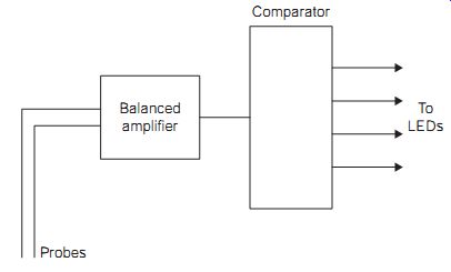
FIG. 1 Block diagram of one type of current tracer. Probes Balanced
amplifier To LEDs
Comparator
An alternative method of tracing current uses a Hall-effect probe which does not rely on sensing voltage, using instead the magnetic field around the track. This type of tracer, such as the Tone Ohm, manufactured by Polar Instruments, will detect partial and complete short-circuits and, with practice, can be used to find the position of an open-circuit.
A current tracer, like a voltmeter, is a useful first test instrument, as it will assist in finding any problems that cause a drastic change in the current flowing along a track. This can help to pinpoint damaged tracks (a hazard particularly in flexible circuit strips) or failure of components that draw large currents, such as printer-head driver transistors. One point to note, however, is that modern PCBs with narrow tracks make the use of any type of current tracer very much more difficult.
Logic probe
A logic probe is a device which uses a small conducting probe to investigate the logic state of a single line. The state of the line is indicated by LEDs, which will indicate high, low or pulsing signals on the line. The probe is of very high impedance, so the loading on the line is negligible.
A typical logic probe can be switched to either TTL or CMOS voltage levels (+5 V supply for TTL and 3-18 V for CMOS) and uses colored LEDs to identify the logic state of the track. Pulses as narrow as 30 ns and as wide as 500 ms can be detected. Some types can also indicate the presence of ripple on the power supply, indicating faulty stabilization. Probes can be battery powered, or can take their power from the circuit under test, using crocodile clips.
These probes are not costly, around $20-70, and are extremely useful for a wide range of work on faults of the simpler type. They will not detect problems of mistiming, but such faults are rare if a circuit has been correctly designed in the first place. Most straightforward circuit problems, which are mainly chip faults or open- or short-circuits, can be discovered by the intelligent use of a logic probe, and since the probe is a pocket-sized instrument it is particularly useful for on-site servicing.
The probe, like the voltmeter used in an analog circuit, has to be used along with some knowledge of the circuit. You cannot expect to gain much from simply probing each line of an unknown circuit. For a circuit about which little is known, however, some probing on the pins of the microprocessor can be very revealing. Since there is a limited number of widely used microprocessor types, it is possible to carry around a set of pinouts for all the microprocessors that will be encountered.
Starting with the most obvious point, the probe will reveal whether a clock pulse is present or not. Quite a surprising number of defective systems go down with this simple fault: it is even more common if the clock circuits are external. Other very obvious points to look for are a permanent activating voltage on a HALT line, or a permanent interrupt voltage, caused by short-circuits. For an intermittently functioning or partly functioning circuit, failure to find pulsing voltages on the higher address lines or on data lines may point to microprocessor or circuit-board faults.
For computers, the description of the fault condition along with know ledge of the service history may be enough to lead to a test of the line that is at fault. The considerable advantage of using logic probes is that they do not interfere with the circuit, are very unlikely to cause problems by their use, and are simple to use. Some 90% of microprocessor system faults are detect able by the use of logic probes, and they should always be the first hardware diagnostic tool that is brought into action against a troublesome circuit.
Logic clips and pulsers
The logic clip is an extension of the logic probe to cover more than one line.
As the name suggests, these devices clip over a logic IC, and are available for 14- or 16-pin DIL packages. Each pin of the IC is connected to a buffer in the logic clip, and this buffer drives an LED indicator. Logic clips are usually available in separate TTL or CMOS versions, although the TTL version is now more common because of the widespread use of 74HC devices.
The logic clip is particularly useful when the system clock rate can be slowed down, or a logic pulser is being used to supply an input. Because all the states on a single IC chip can be monitored together, any fault in a gate within the chip is fairly easy to find, much easier than the use of a logic probe on all signal pins in turn.
Logic pulsers (or digital pulsers) are the companion device to the logic probe. Since the whole of a microprocessor system is software operated, some lines may never be active unless a suitable section of program hap pens to be running. In machine control circuits in particular, this piece of program may not run during any test, and some way will have to be found to test the lines for correct action.
A logic pulser, as the name indicates, will pulse a line briefly, almost irrespective of the loading effect of the chips attached to the line. The injected pulse can be detected by the logic probe. This method is particularly useful in tracing the path of a pulse through several gate and flip-flop stages. A synchronizing pulse can be used to trigger an oscilloscope if needed.
The logic pulser is a more specialized device than the logic probe, and it has to be used with more care. It can, however, be very useful, particularly where a diagnostic program is not available, or for testing actions that can not readily be simulated.
Logic analyzer
The logic analyzer is an instrument which is designed for much more detailed and searching tests on digital circuits in general and on microprocessor circuits in particular. As we have noted, the conventional oscilloscope is of limited use in microprocessor circuits because of the constantly changing signals on the buses as the microprocessor steps through its program. Storage oscilloscopes allow relative timing of transitions to be examined for a limited number of channels, but suitable triggering is seldom available. Logic probes and monitors are useful for checking logic conditions, but are not helpful if the fault is one that concerns the timing of signals on different lines.
The logic analyzer is intended to overcome these problems by allowing a time sample of voltages on many lines to be obtained, stored, and then examined at leisure. Most logic analyzers permit two types of display. One is the timing diagram display, also called timing domain analysis, in which the various logic levels for each line are displayed in sequence, running from left to right on the output screen of the analyzer. A more graphical form of this display can be obtained by connecting a conventional oscilloscope, in which case, the pattern will resemble that which would be obtained from a 16-channel storage oscilloscope. The synchronization may be from the clock of the microprocessor system, or at independent (and higher) clock rates which are more suited to displaying how signal levels change with time.
The other form of display is word display or data domain analysis. This uses a reading of all the sampled signals at each clock edge, and displays the results as a 'word' for each clock pulse rather than as a waveform. If the display is in binary, then the word will show directly the 0 and 1 levels on the various lines. For many purposes, display of the status word in other forms, such as hex, octal, denary or ASCII, may be appropriate. This display, which gives rise to a list of words as the system operates, is often better suited for work on a system that uses buses, such as any microprocessor system.
The triggering of either type of display may be at a single voltage transition, like the triggering of an oscilloscope, or it may be gated by some preset group of signals, such as an address (a trigger word or event). This allows for detecting problems that arise when one particular address is used or one particular instruction is executed. One common method is to trigger a display by using a combination of inputs. One of these would be a trigger word which can be set and stored, the other inputs would be trigger signals (qualifiers) which can be taken from the clock (a clock qualifier) or from other inputs (trigger qualifier). You can also use a word search (trace word or event action) through the memory of the analyzer to find whether a specified word has been stored in the course of an analysis.
The data acquisition portion of an analyzer samples the logic levels at the 16 inputs, using the internal or an external clock pulse to synchronize the sampling. These levels are stored, and in the usual operating mode, the triggering will cause the stored data to be centered around the triggering time.
For example, there may be 2 K of data both before and after the trigger event. Triggering is an ANDed action, so you can set for some combination of signals that is unique, such as when the microprocessor writes a specified word to a chip during an interrupt.
Note that a display such as can be achieved using a logic analyzer can also be obtained from a computer simulator. Simulator software allows the user to notify the chips and connections that are used in a digital circuit, and the program will then provide simulated waveforms. The value of this system is that any unwanted pulses (called glitches) can be detected, even to the extent of a 1 ns pulse that in real life would occur once in 14 days, in the proposed circuit before it has been constructed, and the simulator can also be used to find such weaknesses in an existing circuit. One well-known simulator is PULSAR, from Number One Systems Ltd ( Oak Lane, Bredon, Tewkesbury GL20 7LR, UK). This has the advantage that it can be integrated with circuit diagram and PCB layout software.
Signature analyzer
A signature in this sense means a hexadecimal word, and the signature analyzer is a method of finding an error in any logic circuit, including the memory chips for read-only memory (ROM), erasable programmable read only memory (EPROM) or CMOS random access memory (RAM). The action is that a hexadecimal word is produced from each output when a set of inputs is applied to all the possible inputs of the circuit. This is a more specialized instrument than the others in this section.
The analyzer uses a serial register with feedback taken from four of its parallel outputs to an XOR input. The feedback is applied so that any typical set of inputs will produce a set of bits in the register which is almost certainly unique. The principle, based on information theory, is that a register is working most efficiently when all states are equally likely (an n-bit shift register produces 2n - 1 different output patterns).
Without feedback, a 16 bit register would produce a hex word that would simply reflect the last 16 bits fed into it. For example, if you fed in 16 1s, the register word would be FFFFH, and this would not alter if you continued to feed in 1s. By contrast, with the feedback connections illustrated, the action of feeding in 1s will produce a different register word for each 1 bit fed in, and there will be no repetition until 65536 bits have been fed in. This register arrangement is also used to produce 'random' numbers, and when larger registers are used the chance of recurring numbers becomes less. In the 16 bit example, the words that are generated from 65, 536 or fewer entries are therefore unique, and this allows us to trigger the start and stop of a signature analyzer from the highest order of address line (A15) of an 8 bit microprocessor system, or from the A15 line of a system that uses more than 16 address lines.
The data input to the analyzer will be from any line that produces signals, so that address or data lines can be used. Contact can be made by a probe or a clip. The register is also gated so that it operates for a fixed window, a defined number of clock cycles. In use, the system under test is 'exercised', meaning that inputs are applied, preferably so that all possible signal values are used at the inputs. The register of the signature analyzer will fill with bits in the gated time window, and when the gates have closed, the four hex numbers displayed by the register form a word that should be unique to that combination of inputs and the point that is being tested.
The signature analyzer must be used along with software that ensures that the inputs will be consistent, and a system that is known to be perfect is used to provide the signature words. If a system on test displays a different signature this will point to a fault, and the position of the fault can be found by repeating a signature check at different points along a signal path.
One merit of signature analysis is that the same type of fault at a different point in a circuit will usually produce a different signature word.
Testing of combinational circuits is straightforward, but sequential circuits can be tested only if all feedback connections are broken.
Microprocessor circuits are usually signature tested by inserting an adapter between the microprocessor and its socket. The adapter is designed to allow pins to be open-circuited or connected to either logic level so as to prevent interrupts or to isolate data lines from memory, and also to set a fixed data input such as the no-operation (NOP) code which will allow the clock to cycle the address lines continually. The probe can then be used at each point where a signature is known.
FIG. 2 illustrates the modifications that have to be made to a Z80 microprocessor circuit to carry out signature analysis. The interrupt line is broken so that the interrupt pin can be taken high, and the data bus is also broken so that the NOP command is always on the microprocessor data pins. These changes can be incorporated into an adapter that fits between the microprocessor chip and its normal socket.
===
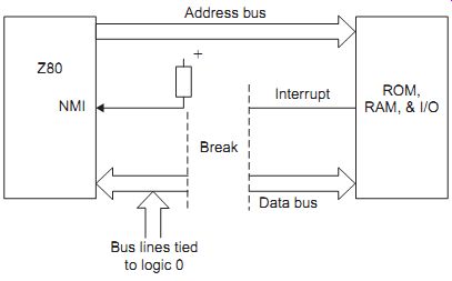
FIG. 2 Signature analysis modifications to a Z80 circuit.
===
A more restricted meaning of signature is applied to the ROM of a computer. The signature can be found in a variety of ways, such as by adding up all the stored byte numbers and taking the remainder after dividing by some factor; whatever method is used will have been devised so that the resulting word is unique and will be found only if the ROM contents are uncorrupted. The word that is obtained in this way will also be stored in the ROM, so that if the two do not match there must be a ROM error. This system can be used also on RAM when the RAM is filled with specified bytes.
Use suitable test equipment to locate faults in systems that make use of combinational logic circuits.
QUIZ:
__1 Why does a service engineer need a good grasp of principles of electricity and electronics?
(a) it shows a good general education
(b) it makes it easier to deal with customers
(c) it makes it easier to use the Internet
(d) not all faults are documented; you need to figure them out for yourself.
__2 Half-split or divide-and-conquer is a method of
(a) testing bits of a circuit at random
(b) logically finding where a fault is located
(c) dividing servicing responsibility between engineers
(d) working with circuits on more than one board.
__3 Negative feedback loops present a servicing problem because
(a) the equipment was originally set up without a feedback loop
(b) the loop might cause oscillation
(c) the loop cannot be disconnected
(d) you cannot be sure where a fault within the loop might lie.
__4 Digital systems require specialized equipment because:
(a) signals have large bandwidths
(b) pulse signals may occur only at intervals
(c) rise and fall times cannot be measured with an analog oscilloscope
(d) pulse shapes cannot be seen on an analog oscilloscope.
__5 The most common problem with circuit boards is:
(a) excessive flux on the board
(b) excessive solder on the board
(c) use of surface-mounted components
(d) cracks and dry joints.
__6 One main advantage of using a digital multimeter is:
(a) quick reading
(b) high input resistance
(c) it can follow rapid voltage changes
(d) more accurate reading