AMAZON multi-meters discounts AMAZON oscilloscope discounts
The modern world is dependent on digital communications. Until relatively recently, radio, television and telephone systems were essentially analog in nature, so, for example, speech carried by a telephone call was represented by continuously varying voltages or currents in proportion to the amplitude of the sound wave to be transmitted. Digital signals from devices such as computers and fax machines were in the minority. Today, however, most systems communicate digitally, including mobile phones, compact disc (CD) and MP3 players, and television systems such as FreeView. One important result of the move to digital communications is the convergence of devices such as televisions and video recorders with computers, or cameras and port able music players with mobile phones, into universal media devices.
The majority of communications, however, still originate in the physical world as sound and images, mainly voice (as in telephone communications), and such signals must be converted to some digital form before they enter the communications links. These communications may be by copper wire, by fiberoptic cable, or by modulated radio waves using either terrestrial or satellite broadcasting.
Connect two digital circuits by a fiberoptic link and verify that signals are being passed.
We class digital signals by their structure and information transfer rate. For convenience, binary digits (bits) are organized into various sized groups. For example, 4 bits form a nibble which can represent one hexadecimal character, and 8 bits form a byte or octet which can be used to represent an alpha numeric or control character from the ASCII (American Standard Code for Information Interchange) code set. A word may consist of several bytes, typically 2, 4 or 8 bytes in length. The data transfer rate may be quoted, depending on the application, in bits, bytes or characters per second.
The term Baud rate may be encountered, and this can cause confusion.
The Baud rate for a communications systems means the symbol rate, where a symbol is the simplest modulating form used and, using suitable modulation techniques, it is possible that each transmitted symbol can represent more than 1 bit of information. If each symbol represents 4 bits, then the bit rate is four times the Baud or symbol rate. Only if each symbol represents 1 bit are the bit and Baud rates equal. Phase shift modulation methods can have a bit rate considerably higher than the Baud rate.
The term Baud rate is often used loosely and incorrectly (particularly in computing) to mean bits per second. For this reason, the term symbol rate is now more often used in digital television engineering applications.
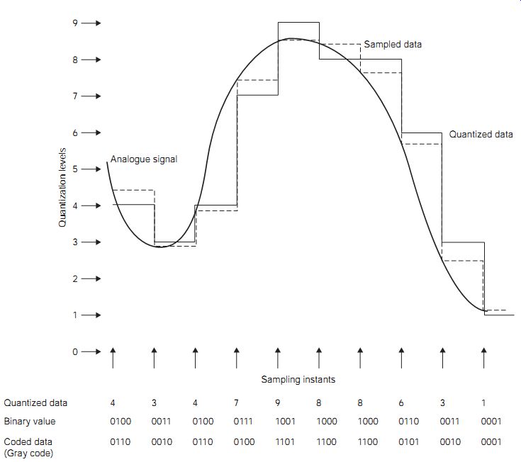
FIG. 1 How PCM data may be derived from an analog signal. Quantized
data Binary value Coded data (Gray code) Sampling instants Sampled data
Quantized data
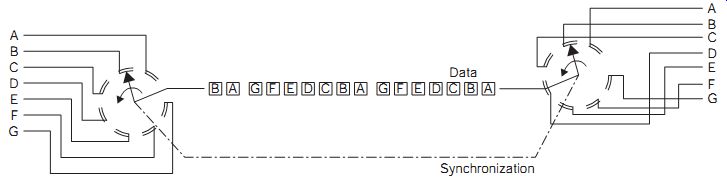
FIG. 2 Simplified schematic of a time division multiplexed communication
link. Synchronization
Pulse code modulation
The form of digital signal that is usually used for speech data is pulse code modulation (PCM), meaning that each unit of data is represented by a binary number. Analog signals are converted to PCM data by sampling, quantizing and coding.
Sampling means finding and storing the amplitude of a signal. By using sampling, the analog signal is broken down into a set of time-related voltage levels (FIG. 1), each of which can be stored until it is converted into a binary number that is proportional to the amplitude of the sample.
Since the binary representation of the analog number must make use of a finite, often quite small, number of levels, the signal amplitude is said to be quantized. This quantized representation of the analog signal is then coded to improve the robustness in communication and sometimes remove redundant data to make the digital communication as efficient as possible.
The output of these sampling, quantizing and coding stages is the PCM data that can then be stored as a file of digital bits or transmitted along digital links. The use of Gray code, as shown in FIG. 1, has advantages, in that in Gray-coded binary, successive numbers only differ by 1 bit; for example, the code for 5 is 0111, while 6 is represented by 0101. This means that the single-bit errors in communication have a relatively small effect on the output data compared with uncoded data.
Conversion of analog signals into digital data and back again is key to the use of digital communications for services such as telephone and television. The notable features of this process are the sampling rate and the resolution; that is, the number of binary digits to represent the level.
The advantages of using digital communication include:
• It can provide a significantly higher transmission speed than can usually be achieved with analog processing.
• It provides for improved transmission quality when electrical noise is present. Since the expected data can only take one of a number of pre defined states, rather than being continuously variable as in analog signals, the noise component can be reduced using error detection/correction techniques. This allows noiseless repeaters or signal regenerators.
• It is more compatible with the digital switching techniques used to control distribution and is a natural technique to use for systems involving an optical fiber link.
• Encryption/decryption can easily be added for data security, at any stage in the link because the characteristics of the signal are well known.
• Where necessary, signal compression/bit rate reduction techniques can be used to minimize the bandwidth requirement.
• For many applications, time division multiplexing (TDM) can be used more effectively than frequency division multiplexing (FDM), which is common for analog transmission systems.
• For systems involving reception and retransmission, signal regeneration can be used at the intermediate stage to improve signal quality.
Time division multiplexing is a method for making efficient use of a communications channel (which may be a radio frequency band, a copper cable or a fiberoptic link) so as to carry more than one channel of information. FIG. 2 shows a simplified example in which a pair of synchronized rotary switches selects the input and output data.
The principle is that a set of bytes from one channel is transmitted, followed by a set from another channel, and so on, until the process is repeated with bytes from the first channel again. This is possible only if:
• the bytes belonging to each channel can be identified at the receiver
• the bytes for any one channel can be assembled in memory at the receiver as fast as they are required
• the rate of sending bytes can be controlled so that the memory at the receiver does not overflow.
Schemes for TDM all depend on the use of packets of data. A data packet is a set of bytes of channel information, such as PCM from a sampled source, together with bytes that indicate the start and end of the packet, with identification to ensure that a packet intended for one channel cannot be confused with a packet for another channel.
In the telephone network the integrated services digital network (ISDN) provides a TDM based link between the customer premises and the local exchange. This is operated over the subscriber's local loop connection in place of an analog telephone service. In contrast, broadband connections typically use asymmetric digital subscriber line (ADSL) and can be opera ted alongside the analog telephone service.
The ISDN link can carry such services as telephony, telex, fax, private digital services and various speeds of circuit switched data service, up to 64 kbits/s. FIG. 3 shows a typical packet structure for ISDN. The start flag indicates the beginning of the packet and can contain a sequence of bits designed to aid synchronization. This is followed by an address that identifies the package. For ISDN, this contains identification codes for the originator of the data and the destination of the data. The control section then contains the packet serial number to ensure that the packets are assembled into the correct order at the receiving end.

FIG. 3 ISDN packet structure -- Start, Address, Control, Payload data,
Frame check, End
The payload data contains the message bytes, typically 256 bytes in each packet. The data bytes are followed by a frame check that is used to provide error protection and correction, and then an end flag to signify the last bit in the packet.
At the receiving end, logic circuits identify each packet and assign it to its correct channel. In each channel, the packets are assembled in memory and fed to their destination, which may be another storage device (such as a hard disk) or another converter such as a digital-to-analog (D-A) converter that will convert the digital data stream into analog format.
This system requires some form of control of transmission rate, so that the memory that is used for packet assembly (the buffer) cannot be overfilled.
The usual scheme is that the rate at which the buffer assembles information is equal to the rate at which D-A conversion is carried out, and the number of channels being carried is calculated to supply the correct rate of packets in each channel. More complex methods are needed when the rate of reading packets may vary.
----
Experiment 1: Use a TDM system to transmit several channels of data through a single path, and separate the channels again.
----
Digital data, encoded and multiplexed as packets, can be transmitted over-fixed links, such as copper or fiberoptic cables, or by way of modulated radio waves. In general, some form of modulation of a carrier is used no matter how the data is transmitted, because modulation systems can be devised that allow very efficient use of the bandwidth of the transmission system (with a bit rate that is much higher than the Baud or symbol rate). The earlier systems used for digital modulation were amplitude shift keying (ASK) and frequency shift keying (FSK).
Amplitude shift keying methods modulate the amplitude of the carrier according to the discrete level of the data signal. For binary modulation, the carrier is simply switched ON or OFF to represent 1 or 0, respectively. This technique is also known as on-off keying (OOK) (FIG. 4). Because ASK and noise signals have similar characteristics (a change in signal level), this form of modulation is not used nowadays because of its poor signal to-noise (S/N) ratio and hence a relatively high bit error rate (BER).
Binary FSK involves switching the carrier wave between two set frequencies. If FSK is used with frequencies in the audio band, typically between 300 Hz and 3 kHz, it is described as audio frequency shift keying (AFSK). One form of this, much used for small computers that stored data on audiotape, is known as Kansas City modulation, for which bursts of eight cycles of 2400 Hz or four cycles of 1200 Hz are used to represent 1 or 0, respectively. Other frequency values can be used and these may or may not have an exact 2:1 ratio. Small differences are often introduced so that beat notes between the two frequencies will not introduce bit errors. Carrier frequency FSK has a better BER performance than ASK under the same conditions, but it requires a wider transmission bandwidth. The AFSK base band signals may be transmitted over cable or radio links by other techniques such as amplitude modulation (AM) or frequency modulation (FM).
Phase shift keying (PSK) is a more modern single-frequency modulation method in which the data signal is used to shift the carrier phase. Typically, for binary transmission a 0 produces no effect while a 1 generates 180° of carrier phase shift. Of the three methods we have looked at, PSK has the best BER performance and the narrowest transmission bandwidth, so modern methods of digital communications all make use of some form of PSK.
For cable transmissions, either copper or fiberoptic, multiphase PSK, in which the modulated carrier can carry a number of different phase shifts, can be used to advantage. FIG. 5(a) shows the relationship between various amplitude and phase shifts and their vector diagrams. When both phase and amplitude modulation is used, the modulation is called quadrature amplitude modulation (QAM). FIG. 6(a) shows an example of 8-PSK where each vector can be used to represent 3 bits of information so that the Baud rate is just one-third of the bit rate. The concept of 4-PSK or quadrature PSK (QPSK) can be usefully extended in several ways. For example, if each of the four vectors is permitted to have any one of four different amplitudes, then each vector can be used to represent 4 bits. FIG. 6(b) shows one example of such QAM (16-QAM), in which the signal points in the matrix form a constellation. Cable digital television systems can make use of even more bits of PSK, and one common system is 64-QAM.
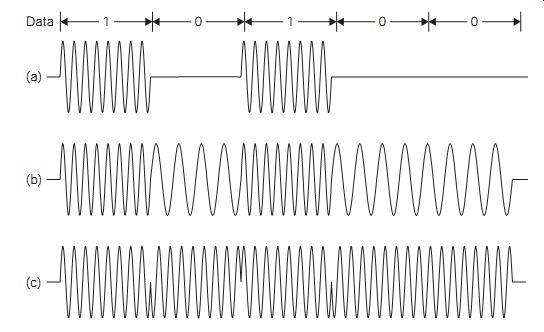
FIG. 4 Digital modulation: (a) OOK, (b) FSK, and (c) PSK
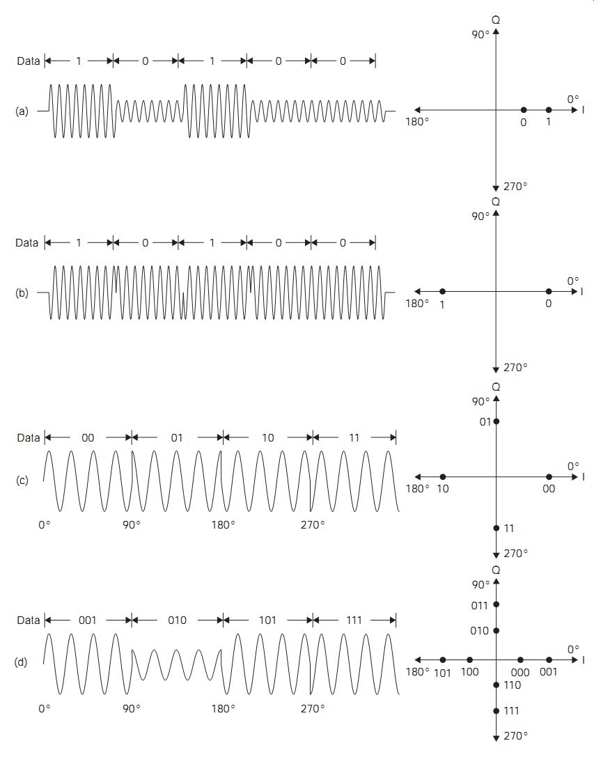
FIG. 5 Multi-amplitude and multiphase keying: (a) two-level ASK,
(b) BPSK, (c) 4-PSK, and (d) 8-QAM
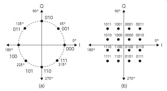
FIG. 6 Digital modulation: (a) 8-PSK, and (b) 16-QAM
Digital data streams containing long sequences of ones or zeros can be used within a computer, but they are not ideal for transmission. For example, a long stream of bits of the same value is rather like a very low-frequency analog signal. This can cause problems with data transmission and recovery in receivers, and methods, classed as secondary encoding, have to be used to ensure acceptable performance. Similar problems are encountered with raw data recording on magnetic and other media.
Digital communications systems are more robust than the equivalent analog systems in the presence of noise. This is clearly seen by reference to FIG. 7(a), which shows how even a relatively noisy signal can be recovered correctly. FIG. 7(b) further compares analog and digital signals under the same S/N ratio at the input.
While the analog system degrades gracefully before it fails, the digital system is relatively unaffected by the noise until a point is reached, when the system suddenly crashes as the BER rises. However, the advantages of digital technology do not end here. There are a number of ways in which the information can be accurately recovered even from signals with a high BER, providing that the time scale is not critical.
At the simplest level of communication between two computers, a system known as automatic request for repeat (ARQ) is available. Reference to the ASCII code table shows that two special codes are available, ACK (acknowledge) and NAK (negative acknowledge). If a distant receiver detects a code pattern without errors, it transmits via a return channel the code ACK. However, if errors have been detected, transmission of the NAK code automatically generates a request for a repeat transmission of the last block of signal code.
Furthermore, bit errors can be detected and even corrected in a digital system using a technique known as forward error correction (FEC). This is so called because the means of error detection/correction are contained within the transmitted message stream. This is achieved by the addition of extra redundant bits which, when suitably processed, are capable of identifying the errors. Either method makes extra demands on the spectrum; FEC requires additional time or bandwidth to include the extra bits, while the ARQ system requires a free return channel.
The prime causes of bit errors are white noise and impulsive noise.
White noise produces errors that are completely uncorrelated and random in occurrence, and impulsive noise creates a loss of bit stream synchronism, which leads to bursts of errors.
Three classes of error need to be considered:
1. detectable and correctable
2. detectable but not correctable
3. undetectable and hence uncorrectable.
==
Transmitted data
Recovered data
Recovered data
Recovered data
Recovered data
16 dB S/N signal 8 dB S/N signal 6 dB S/N signal 3 dB S/N signal
1/Bit error rate Noise free system Digital communication system Analog communication system Output signal quality
==
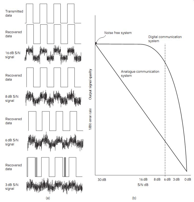
FIG. 7 (a) Effect of noise on digital signal recovery, and (b) comparison
of analog and digital system behavior in noisy conditions
------------
For any errors detected as type 2, the error can be concealed even if it can not be corrected. The concealment options are:
• ignore the error and treat it as a zero level
• repeat the last known correct value
• interpolate between two known correct values.
Forward error correction can significantly enhance the resistance to noise interference for a digital communications system in a noisy environment.
Comparatively simple methods can be applied to coded text that uses the ASCII code system. This 7 bit code allows for 2^7 = 128 different alphabetic, numeric and control characters. The most commonly used digital word length is 8 bits or 1 byte (2^8 = 256), and therefore there is space for one extra redundant bit in each code pattern. Note that this spare bit is not avail able for extended ASCII codes (used by word-processing programs) that use all eight bits.
A single-error detection (SED) code of n binary digits is produced by placing n - 1 information or message bits in the first n - 1 bit positions of each word. The nth position is then filled with a 0 or 1 (the parity bit), chosen so that the entire code word contains an even number of 1s. For example, using an 8 bit byte to convey a 7 bit item of data allows the 8th bit to be used as a parity bit. If a code word that has been adjusted for even parity is received over a noisy link and is found to contain an odd number of 1s, then an error must have occurred.
Alternatively, a system may use odd parity, where the nth bit is such that the code word will contain an odd number of 1s. In either case, a parity check at the receiver will detect when an odd number of errors has occurred. The effect of suffering two (or any other even number) errors is self-cancelling, so these will pass undetected. The even or odd parity bits can be generated or tested using exclusive OR or exclusive NOR logic, respectively.
Such a pattern of bits is described as an (n,k) code, n bits long and containing k bits of information. The simple example of ASCII code is an (8,7) code.
It thus follows that there are n - k = c parity (or protection) bits in each code word. The set of 2k possible code words is described as a block or linear code. ASCII uses 2^7 = 128 words in a block code. At one time, all memory used in personal computers (PCs) allowed for 9 bit storage, so that a parity bit was available for checking memory integrity. This scheme is no longer used because memory is more reliable now, and there are better ways of checking memory integrity (such as by successive writing and reading methods).
The simple parity scheme that provides only a low level of error control is suitable only for systems that operate in relatively low levels of noise.
The weak point of the system is that a single error may affect a parity bit, causing a valid byte to be rejected. In addition, the system is useful only in a communications link where a fault detected at the receiver can be signaled to the transmitter so that a block can be sent again.
The check-sum error control scheme is often used with magnetic storage media where data is stored in long addressable blocks. It is a simple scheme in which the digital sum of all the numbers in any block is stored at the end of each block. Recalculating the check sum and comparing the original and the new values after each data transfer quickly tests whether any read errors have occurred. For example, if the following binary words 0101 (5), 0011 (3), 1010 (10) and 0010 (2) are valid, then the check sum would be 10100 (20). If after a read operation the numbers became 0101 (5), 0011 (3), 1001 (9) and 0010 (2), the check sum should be 10011 (19). Comparison of the check sums shows that a read error has occurred and the block should be read again.
The simple check-sum technique can only identify when an error occurs and cannot indicate the position of the actual error. However, this problem can be overcome by using a weighting scheme that employs a series of prime numbers (any number that cannot be divided perfectly by any other number except for 1 and itself).
By multiplying each data number by a prime number, the check sum that is formed carries position information, and subtracting the true (transmit ted) check sum from the false check sum (obtained by repeating the check sum formation on the received faulty data) will give the multiplier number for the data digit that is in error.
This can be most easily explained using a series of denary numbers.
Suppose we use the prime numbers 1, 3, 5 and 7, and the decimal values to be stored and read are 5, 3, 9 and 2. The weighted check sum would calculated by multiplying each data number by the corresponding prime number.
In this example, it would be:
1 x 5 + 3 _ 3 _ 5 _ 9 _ 7 _ 2 = 5 _ 9 _ 45 _ 14 = 73
The sequence would thus be stored as 5, 3, 9, 2, 73.
If on reading this became 5, 3, 8, 2, 73, the recalculated check-sum would be:
1 x 5 + 3 x 3 + 5 x 8 + 7 x 2 = 5 + 9 + 40 + 14 = 68
The check-sums are different, so an error has occurred, but the difference is 73 - 68 = 5.
Therefore a unit error has occurred in the 5-weighted value, the data number that was multiplied by 5 in this example, which was originally 9 and has become 8 because of the error. When this scheme is applied to a binary number, correction is simple, because if the digit 0 is an error, the true value is 1 and vice versa.
Much more advanced error correcting codes have been devised, and one type is named after R. W. Hamming, who was the originator of much of the early work on error control. Hamming code schemes are particularly useful for systems that require a high level of data integrity and operate in noisy environments that create random bit errors.
The cyclic redundancy check (CRC) system is most effective in combating burst errors. To generate the code for transmission, three code words are used. These are a message code word k, a generator code word G (selected to produce the desired characteristics of block-length and error detection/ correction capability) and a parity check code word c. As for block codes, the transmission code word length is given by n = k + c. During encoding, the message k is loaded into a shift register and then moved c bits to the left, to make room for c parity bits. The register contents are then divided by the generator code word to produce a remainder that forms the parity check code word c, which is then loaded into the remaining shift register cells.
Thus, if the total code word were transmitted and received without error, this when divided by G, would yield a zero remainder. The last c bits can then be discarded to leave the original message code word. If however, an error occurs, then division by G leaves a remainder code word that acts as a syndrome. There is a one-to-one relationship between this and the error pattern, so that any correctable errors can be inverted by the error correcting logic within the decoder. The effectiveness of these codes depends largely on the generator code word, which has to be carefully selected. A further advantage is that CRC can be operated with microprocessor-based coding, when the system characteristics become reprogrammable.
Several other techniques have been developed from the basic Hamming concepts to deal with both random and bursts of errors. These include BCH codes for random error control, Golay codes for random and burst error control, and Reed-Solomon codes for random and very long burst errors with an economy of parity bits. Reed-Solomon coding is used for the CD recording system.
FIG. 8 Commonly used code formats: (a) return to zero, (b) NRZ version, and (c) Manchester (biphase)
Primary and secondary codes
For a simple transmission system of number codes (primary codes) the BER can be minimized by using pulses of maximum width and/or amplitude, the obvious choice being a square shape. However, this introduces a number of problems. To pass a square wave, a transmission channel requires a wide bandwidth. To retain a good approximation to a square wave requires that the channel bandwidth should extend up to at least the 13th harmonic of the fundamental frequency. In any case, the transmission of such pulses through a typical channel will produce dispersion or pulse spreading, which leads to a type of error called intersymbol interference and an increase in the BER. Increased pulse width reduces the signaling speed and an increase in pulse amplitude introduces further problems. The final pulse shape is thus a compromise. One particularly useful pulse shape is described as a raised cosine. This shape is chosen because half of the pulse energy is contained within a bandwidth of half the bit rate.
A code format is a set of rules that defines clearly and with no room for mistakes the way in which binary digits can be used to represent alphabetic, numeric, graphic and control character symbols. The PCM code is one useful format, but other formats can be used with advantage to reduce the BER when noise is likely to corrupt a transmission. Such changes to the original set of codes are called secondary codes.
Shannon's rule states that the communication channel capacity, in bits/ second, is related to the available bandwidth and the S/N ratio. It also shows that these two parameters can be balanced to maximize the channel capacity for an acceptable BER suitable for a particular service.
To take advantage of this tradeoff, binary code formats are redesigned by inserting extra bits into the data stream in a controlled way. Some of the formats used are shown in FIG. 8. The general aim is to minimize the number of similar consecutive bits and balance the number of 1s and 0s in the message stream. The greater number of signal transitions is used to improve the locking of the receiver clock and so reduce bit errors. The balance between the number of 1s and 0s produces a signal without a d.c. component in its power spectrum. This allows a.c. coupling to be used in the receiver and reduce its low-frequency response requirement. The commonly used codes are generated and decoded using dedicated integrated circuits [application-specific integrated circuits (ASICs)].
The return-to-zero (RZ) data, where a 1 is represented by a half-width pulse and a 0 by an absent pulse, is shown in FIG. 8(a). This is a simple way of coding PCM, and it was used extensively in early telegraphy, but it is seldom used now because long runs of zeros can lead to synchronizing difficulties and because the reduced-width pulses require more energy to be transmitted per bit that in other coding methods.
Non-return-to-zero (NRZ) data is a signaling method in which a 1 is signified by a full-width pulse and a 0 by no pulse (FIG. 8b). Long runs of 1s can lead to d.c. offset in the data communication system, which can cause problems in data transmission and recovery; long runs of 0s can also lead to synchronizing difficulties.
The Manchester code shown in FIG. 8(c) is one of a number of biphase data formats, which are popular because they contain both clock and data information, making them useful for remote control applications, in which each bit in the original signal is represented by the direction of a transition in the center of the bit period. The Manchester code is most easily derived by XORing the data and clock signals, as can be seen by studying FIG. 8. Another way of looking at Manchester data is to observe that each bit is represented by a 2 bit long symbol; the transform is that 0 is represented by 10 and 1 by 01. Biphase data ensures that there are never more than two identical bits in series; this avoids the problems of d.c. off sets and synchronization suffered by both RZ and NRZ codes. Another variant of the Manchester format uses the opposite pair of symbols.
Another modulation format it that used by CD systems EFM (eleven to-fourteen modulation) as a way of overcoming the problems of recording on CD media. In this system, the 8 bit code has been extended to 11 bits with parity bits, and each 11 bit number is transformed into a 14 bit number for recording. The 14 bit numbers are chosen so as to avoid the repetition of a digit or the rapid changes between 0 and 1 that can be troublesome in a recording or replay action.
The pure binary, 8-4-2-1, type of code is not the only binary code that we can use, and several others are likely to be encountered, depending on the type of applications. One very common variant of the 8-4-2-1 code is binary-coded decimal (BCD). This is a very popular form of coding when numbers have to be shown on liquid crystal display (LCD) or light-emitting diode (LED) displays, because each digit of such a display is one denary digit. It is also frequently used in process control equipment for the same reason, and some microcontrollers have BCD arithmetic instructions, which greatly simplify handling BCD numbers.
In a BCD system, then, each denary digit is represented by 4 bit binary code. Table 38.1 demonstrates what this implies. The conversion between BCD and denary is simple, and conversion to a form suitable for driving a display is also simple. The conversion between BCD and binary is, however, not quite so simple for numbers of more than one digit, and arithmetic with BCD is also not so simple. An added disadvantage is that BCD requires more storage space for any given number than 8-4-2-1 binary, although it is possible to devise systems in which number accuracy of floating point numbers can be much better, at the cost of very much slower arithmetical processes.
==
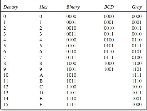
Table 1 Denary, hexadecimal, binary, BCD and Gray code equivalents Denary Hex Binary BCD Gray
==
BCD is really just an adaptation of 8-4-2-1 binary, but Gray code is quite a different form. As Table 38.1 shows, a Gray code scale does not use columns to indicate the value of a bit, and you always have to use a table to convert a number in Gray code to a denary or a binary 8-4-2-1 number. The Gray code numbers are for 4 bits only, because Gray code is used either in BCD form, or in a scale of 16 (hexadecimal). The Gray code is sometimes called the binary reflected code.
The advantage of Gray code is that only one bit ever changes at a time during a count-up. The change from 7 to 8, for example, is from 0100 to 1100, rather than from 0111 to 1000 in the 8-4-2-1 binary code. Gray code has particular advantages for conversion of quantities such as the rotation of a shaft into binary form, because if the shaft is in a position between the angles represented by numbers 7 and 8, then there may be reading errors caused by some binary digits that are changing between 0 and 1, and the fewer digits that change, the lower the chances of error.
There are other forms of binary code, such as Excess-3, which is a form of BCD in which 3 is added to each digit before coding into 8-4-2-1 binary.
This means that the smallest value of code is 0011 and the largest is 1100, with anything below 0011 or above 1100 being an error. This makes error detection easier, and also has the considerable advantage that BCD numbers coded in this way can be manipulated by the same circuits as ordinary binary. The Gray code and the various forms of 8-4-2-1 code are, however, by far the predominant methods of coding that you are likely to encounter.
QUIZ:
__1 A data link transmits 8 bit data and has a Baud rate of 300 symbols per second. If the data is encoded as 1 bit per symbol with a start bit a parity bit and 2 stop bits per frame, what is the data bit rate of the link?
(a) 300 bits/s
(b) 200 bits/s
(c) 120 bits/s
(d) 100 bits/s.
__2 A 16-QAM data link operates at 100k symbols per second. What is the bit rate of the raw data stream. (i.e. including error correcting codes and packet control bits)?
(a) 100 kbits/s
(b) 800 kbits/s
(c) 1.6 Mbits/s
(d) 6.4 Mbits/s.
__3 What is the effect of using even parity on the bits in an n bit message block?
(a) there will be an even number of zeros
(b) there will be the same number of zeros as ones
(c) there will be an even number of ones
(d) there will be more ones than zeros.
__4 What are the main advantages of using Manchester code to transmit data?
(a) it increases the data rate and symbol rate
(b) it minimizes d.c. signal offsets and maintains synchronization
(c) it reduces the energy required and minimized d.c. offsets
(d) it only transmits when bit values change and increases the data rate.
__5 How would the decimal number 127 be represented in BCD?
(a) 0001 0010 0111
(b) 0111 0001 0010
(c) 1000 1001 1110
(d) 0000 0111 1111.
__6 The main feature of TDM systems is that:
(a) data is transmitted as soon as it is available to the system
(b) data is transmitted in parallel packets using multiple pairs of wires
(c) multiple data channels are transmitted sequentially over one physical channel
(d) data is transmitted over fiberoptic links using modulated laser diodes.