AMAZON multi-meters discounts AMAZON oscilloscope discounts
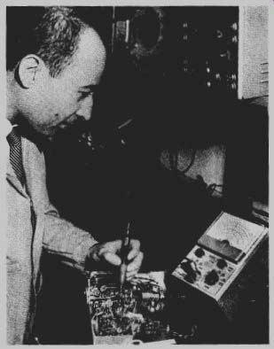
Fig. 1--As a hobby, electronic experimenting offers the thrill of accomplishment
and knowledge of the most fascinating science of our day.
ELECTRONIC experimenting, one of the fastest growing hobbies in the world, is also one of the most exciting. A few tubes or transistors, some resistors and capacitors, and you can be in touch with radio stations all over the world or with an earth satellite speeding through space. The hobby requires little in the way of money, or even knowledge at the start, but will pay off right away in successful projects and will furnish you with a store of electronic know-how for those more exciting projects to come.
In addition to the fun, there are practical benefits from electronic experimenting. Around your home you will find many opportunities to apply your electronic know-how. Garage-door openers, intercoms, and remote-control devices are only a few of the projects you may undertake to improve your home.
Experimenting can also be a stepping-stone to a real career in electronics. Many electronic technicians received their basic training at their home workbenches. The construction projects detailed in the later sections of this guide will help to give you an understanding of many of the basic principles of electronics.
With about 5 dollars invested in tools (you probably have most of them around the house now) and a bit more invested in parts you can start in electronics. What will your first project be? A short-wave receiver for listening to London, Paris, or Moscow? A transistor radio half the size of a pack of cigarettes? That's up to you. Pick the one you want, and you're on your way.
You don't have to know all about electronics to get started on your project. Any project in this guide or in the popular electronics magazines can be built simply by following instructions. This method is all right for the beginning, but as you become more familiar with circuits and parts you will want to know more about what makes them work.
Building any electronic project is a matter of following a series of simple steps. To help you to understand these steps, the first sections of this guide have been arranged in such a step-wise order.
The first step is to read over the instructions and study the circuit diagram or pictorial layout. Looking at the photographs of the finished equipment will give you a good idea of where the parts should be placed on the chassis. The next step is to gather together the parts needed; to become familiar with their shape and size and how they are mounted on the chassis. The third step is to lay out the parts on this chassis, drilling holes where required. The fourth step is to mount the parts and do the wiring job. The final step is a check of your wiring for errors, making necessary adjustments.
Then you're ready to put your project into operation.
Each of these stages will be covered in detail in future sections, but before we proceed, there are some basic things you should know about building electronic equipment-how to use your tools, how to solder, how to work with wire, and what kind of wire to use.
Tools
The basic tool kit of an electronic experimenter consists of a soldering iron or gun, a set of screwdrivers, and two pairs of pliers. These are the tools of wiring. Other tools, such as drills and saws, will be required to build chassis and cabinets for equipment. These additional tools will be discussed in the section on chassis construction.
Of all your tools, you will probably use your soldering iron or gun more than any other, for this is the basic tool of electronic construction.
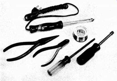
Fig. 2--The basic tools of the electronic experimenter.
To ensure that they will conduct electricity properly, every joint in an electronic circuit must be soldered. Although soldering is a simple procedure, it must be done correctly each time. One improperly soldered joint in a circuit is enough to make the entire circuit inoperative.
Tracking down the results of poor workmanship in a complicated circuit can take hours of your time and rob you of the fun of seeing your project "come to life" when you turn it on for the first time.
Because your soldering tool is so important in your work, you should choose it carefully and learn how to use it properly. There are two types of soldering tools--the soldering iron and the soldering gun.
Both types are shown in Fig. 3. Most of us are familiar with a soldering iron, but the soldering gun is a more recent development that has rapidly become a favorite with technicians, repairmen, and experimenters.
Care should be taken in selecting a soldering iron. Too large an iron can be hard to handle and may deliver too much heat to the joint, resulting in burned insulation and damaged components. If the iron is too small, it may deliver too little heat to melt the solder sufficiently to make a good electrical connection. A good basic iron for the electronic experimenter should be rated at 100 to 150 watts. This will give enough heat to handle most jobs.
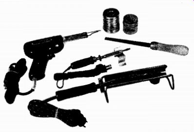
Fig. 3--General-purpose soldering gun at top has built-in spotlight. Small
soldering iron at center is useful for printed circuit work and miniaturized
projects. Large iron at bottom is suitable for most types of electronic work.
If you intend to do a lot of work with miniature equipment, transistor circuits, and similar small items, a 25- to 60-watt soldering "pencil" is preferable. This iron will provide enough heat to solder small joints and has a small enough tip to let you see what you are doing.
Most soldering irons and pencils come with two or three inter changeable tips. If the iron you buy does not come with a set of tips, pick up a couple of extra ones. A long, thin tip will come in handy in many tight spots, and a large one is useful for heating large areas.
A soldering gun, though more expensive than an iron, has many attractive features. An on-off switch permits you to turn the gun on only when you need it. The tip heats almost instantly when the trigger is pressed and cools down quickly when the switch is released. There is less danger of burning things (including yourself) with a soldering gun.
Furthermore, most guns have two focused spotlights built into the body that illuminate the work area when the gun is in use. A 100-watt gun is small, lightweight, and easy to handle. Its heat is sufficient for almost all jobs, from making small connections to soldering a fairly heavy ground to the chassis. If you are going to do a lot of heavy-duty work, a 250-watt gun might be preferable.
The narrow tip of a soldering gun is especially useful for getting into the deep, dark corners of a chassis or working in the tight places of miniature circuits and printed-circuit boards. The tips can also be bent to reach around corners.
Solder and Flux
Solder and flux are used with a soldering iron to join two materials.
The flux helps the solder "wet" the surface of the materials, by removing oxidized surface film, so that the solder can penetrate the pores of the material. The flux itself does not react with the metals being soldered, but it is necessary in order to solder a joint properly. In electronic work, a rosin flux is always used. Acid flux solder is also available, but it should never be used in electronic equipment. Although a piece of equipment assembled by the use of acid flux may work properly at first, the acid will gradually corrode the joint and build up an oxide that will prevent electrical flow through the connections.
For electronic work, a 50-50 or 60-40 wire solder is preferred. The first figure refers to the percentage of tin; the second refers to the percentage of lead in the alloy. In general, the higher the percentage of tin, the lower the melting point of the alloy.
Most experimenters and servicemen prefer to use cored solder. This is a hollow tube of solder with flux in the core. When the solder is heated, the flux melts first and flows out over the joint. The solder then melts and makes the connection.
Soldering Technique
Soldering with either iron or gun follows exactly the same procedure. The joint is heated; solder and flux are applied and allowed to flow over the joint; the heat is removed; and the joint is allowed to cool.
That's all there is to it. However, there are several important points that must be observed to ensure a good soldering technique.
First of all, the joint must be clean. All grease, dirt, corrosion, or enamel must be removed from the surface of the metal before the joint is soldered. Use steel wool, sandpaper, a file, knife, or wire brush to do this job. Clean the surface until bright metal shows through at the point to be soldered.
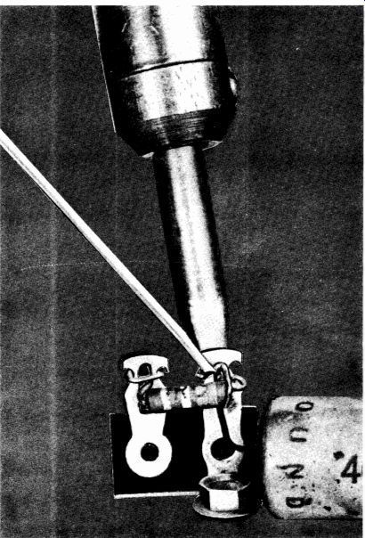
Fig. 4-Correct soldering technique.
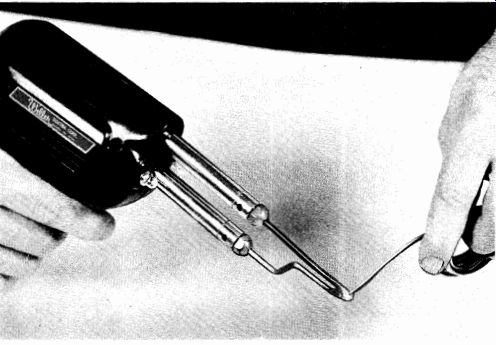
Fig. 5-Tinning the tip of a soldering gun.
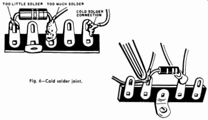
Fig. 6-Cold solder joint.
Next, heat the joint to a temperature high enough to melt the solder. This is the secret of good soldering! Never touch the solder to the iron to melt it. Heat the joint and touch the solder to the point you want to solder. The solder will melt and flow over the wires. Don't keep the iron on the joint too long. As soon as the solder flows, remove the soldering iron and let the joint cool. Don't be tempted to wiggle the joint to test it. If you do, you may ruin an otherwise perfect connection. Let your testing wait until the joint has completely cooled.
A final trick in good soldering is to keep the soldering-iron tip clean and well tinned. If the tip of the iron is not clean, a film of oxidation will form and prevent heat from reaching the joint. Tinning is simply keeping the tip covered with a coating of solder (see Fig. 5). This is done to ensure the quickest possible transfer of heat from the tip to the work. To tin an iron simply heat it and apply solder to the tip.
A cold solder joint will result from insufficient heat: You will recognize the cold solder joint from its rough, grainy appearance compared to the smooth, shiny surface of the well-soldered joint (see Fig. 6). To repair a cold solder joint apply the hot soldering iron until the solder begins to flow. That's all there is to it.
Screwdrivers
Next to your soldering iron, your screwdrivers are the tools you will reach for most often on a project. At first, one with a 4-inch shaft and a 3/16-inch tip will serve nearly all your requirements. Later, you will want other sizes, including screwdrivers with longer shafts to reach out-of-the-way places and a couple of stubby ones for the tight spots.
There are two main types of screwdrivers-the familiar flat-bladed kind and those with an "X"-shaped tip known as "Phillips-head" screwdrivers. While you are assembling your own projects, you will not need the Phillips-head screwdriver.
However, when you start to work on commercial electronic equipment or to build kits you will require a few of these. Phillips-head screws are often used on the outside finished panels of equipment because there is less likelihood that a Phillips-head screwdriver will slip out of the slot and scratch the finish.
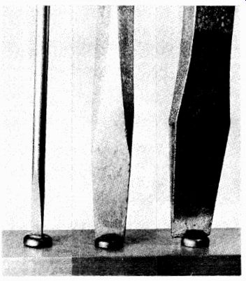
Fig. 7--The screwdriver at the left k too small; its blade could snap. Screwdriver
at right is too large and could damage screw.
Screwdriver in center fits snugly into slot arid has proper width.
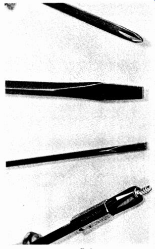
Fig. 8
When you use the correct flat-bladed screwdriver, there is little chance of its slipping either. The right size screwdriver is the one that fits the slot snugly, as shown in Fig. 7. If the blade is too small, it may break.
If the blade is too large, you may damage the slot in the screw, in which event it will be almost impossible to turn even when the right screwdriver is used.
The screw-holding type of screwdriver shown in Fig. 8 has a device that holds the head of the screw firmly against the blade of the screw driver. With this handy tool, you can insert screws in hard-to-reach places. A magnetized-head screwdriver can also be used for this purpose; it will also be useful to retrieve bolts and nuts. However, it can also become a nuisance by picking up bits of metal and scraps when you are using it for ordinary jobs.
Another useful type is the jeweler's screwdriver. This is a very small-tipped screwdriver with a rotating top. It is held in one hand, pressure is applied to the screw by placing the index finger on top of the screw driver, and the shaft is rotated between the thumb and middle finger.
You will find this tool very useful for work with miniature equipment.
The jeweler's screwdriver is also available in sets with a number of interchangeable blades.
Pliers
Pliers can be used to bend and cut wires, to strip insulation, and to hold small parts and nuts. The most useful pliers for the experimenter are the long-nose type, which have a cutting blade at the end of the jaws closest to the joint. These pliers will handle all of the jobs required in electronic construction. They are especially useful to bend wires and squeeze leads in tight places, but the position of the cutting blade makes it impossible to cut wires close to the chassis. Therefore, you should also own a pair of side cutters. The side cutter has a cutting blade that extends out to the tip of the jaws, so that you can make a cut anywhere you can insert the tip.
A pair of gas pliers is also handy for holding nuts and doing heavy bending work. The long-nose pliers should never be used for heavy work. Too much pressure will spring or break the jaws.
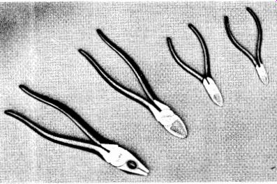
Fig. 9-Side cutting pliers (right) and lineman's pliers (left).
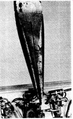
Fig. 10-Long-nose pliers.
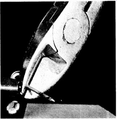
Fig. 11-Side cutting pliers provide close cutting to trim leads and to cut
wires to size.
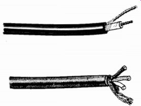
Fig. 12-Two types of shielded cable, single conductor (top) and three-conductor
(bottom).
Shielded cable is used to protect low-level signals from stray electrical fields.
Wire
In addition to tools, every electronic experimenter needs wire to hook up the electronic parts and, also, hardware to mount the parts on a chassis.
Two types of hookup wire are used in electronic work-solid and stranded. These wires are available with various types of insulation, including enamel, cloth, and plastic. Solid wire is available also without insulation, or bare. In addition, wire is available in various sizes ranging from No. 40 (about 3/1000 inch in diameter) up to a size of No. 0000 (almost 1/2 inch in diameter). These size numbers are the American Wire Gage (AWG) sizes.
If this sounds like a lot of wire to have in stock, you are right! Actually, for electronic work, you will need only three or four sizes. Practically all of your circuit wiring can be done with a No. 20 or No. 22 solid, plastic-covered wire. This wire is available from your radio parts house in 25- and 100-foot rolls.
Solid wire is useful for making connections between parts in a circuit, such as between tube sockets and terminal strips. Because solid wire is stiff, it will remain in any shape to which it is bent and so will make a neat appearing wiring job. However, if solid wire is subjected to repeated bending, it will snap. When you need flexibility, stranded wire should be used. This type of wire can withstand vibration or frequent change of position with little danger of breaking.
It is slightly more time consuming to make connections with stranded wire than with solid wire. It is necessary to twist all of the strands together before inserting the wire into a terminal hole. If this is not done, loose strands 'may spread out in all directions when the wire is inserted. If the connection points in a circuit are close together, some of the strands may touch another terminal causing a hard-to-find short circuit. When working with stranded wire, coat the twisted strands with solder before hooking up the wire. This will keep the strands from unraveling.
The various types of wire insulation are important to the experimenter. Plastic-covered wire will take care of 90 percent of your wiring jobs. Such wire has almost entirely replaced cloth-covered wire for general electronic wiring. With cloth-covered wire, it is often difficult to remove all of the strands of cloth when removing the insulation from the end of a wire. With the plastic-covered wire, a quick flick of the knife will remove the insulation neatly.
Because the enamel coating is very thin, an enamel-covered wire is often used in winding coils and in similar applications where it is necessary to get the wires close together.
The only other type of wire required by the electronic experimenter is shielded, or coaxial, wire. This is used in low-level audio and high-frequency circuits. It is simply a conventional plastic-covered wire with a mesh shielding wrapped around. The shielding may be bare or have a rubber or plastic covering. The inner conductor is connected into the circuit (as with conventional wire), and the shielding, or outer conductor, is attached to a ground point at one or both ends. The shielding acts as a guard to prevent stray electric signals from being picked up by the inner conductor.
Working with Wires
Good technique in wiring will give you a finished project that will look neat and will perform properly. Most experimenters prefer to use the point-to-point method of wiring. This technique requires that you cut each wire to a length that will reach the two points to be connected by the shortest possible route. In high-frequency circuits, point-to-point wiring is a necessity because the length of a wire may affect the operation of some critical circuits. In general, it is a good rule to make every wire as short as possible, but not so short that it will put a strain on the terminal. The exception to this rule is in the wiring of filament supplies of tubes. These wires should be twisted together, as shown in Fig. 13, and should be placed as far from the input wiring as possible. Here, it is O.K. to make the wires as long as necessary to keep them away from other wiring in the circuit. If the filament wiring is too close to signal-handling wires, the a.c. current they carry may cause hum in the operating circuits of the equipment.
Fig. 13
Another exception to the rule of point-to-point wiring is met when a construction project specifies that wires be placed in a certain position. These instructions should be followed precisely. It is not always obvious to the experimenter why these wires should be placed in a certain position. Often, it is not obvious to the original designer of the equipment, either. Frequently, an original piece of equipment is built, and then the designer spends considerable time changing wire lengths and positions of parts to get the circuit to operate at its best.
Wiring Techniques
There are two ways to do a wiring job. Both are good techniques, and you will probably use both, depending on the project on which you are working. For the beginner, the first technique is probably the easiest. First measure the distance between the two points to be connected. Then add 1/2 inch (1/4 inch for the connection at each end) to that length. Cut a piece of wire to this length. Bare N inch at each end of the wire using a knife or wire strippers. If you use a knife, be careful not to cut into the wire. A nick may cause the wire to snap after it has been in service for some time. In stranded wire, nicking may cause some of the strands to fall off and leave you with a smaller size wire than the circuit calls for.
To bare plastic-covered wire properly when using a knife, place the wire between your thumb and the blade of the knife. Press your thumb gently on the knife blade and pull the wire with the other hand. The insulation should break at the knife blade leaving the bare conductor.
A convenient tool for removing insulation from the end of a wire is shown in Fig. 14. When used like a pair of pliers, the wire stripper will remove insulation in one step with no danger of nicking the wire. A guide on the side of the blade permits you to set the tool to bare exactly the length of wire you want. A simpler and less-expensive wire stripper consists of a pliers-like unit with one blade notched to accept popular sizes of wire. The cutting blade is set to enter the notch only far enough to cut the insulation.
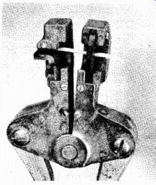
Fig. 14--Wire strippers remove insulating up to the desired point with one
squeeze of the handles.
PERMANENT JOINT TEMPORARY "HOOK" JOINT "LAP" CONNECTION
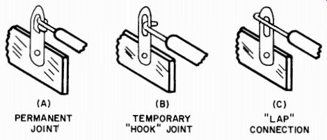
Fig. 15--Three types of mechanical connection used in soldering.
After the end of the wire has been prepared, form a small loop in the wire with the long-nose pliers and place the loop through the hole in the terminal. Then close the loop tightly around the terminal.
Do the same at the other terminal and solder both joints if there are no other wires to be connected to these terminals.
An alternative wiring method is to bare the end of the wire on the spool and connect it to one of the terminals. Then lay the wire in place, clipping it from the spool at the point where it reaches the other terminal. Bare this end of the wire and hook it into place. This method usually gives the shortest possible wire length because it is measured right in place. It also eliminates the need for making measurements with a ruler and transferring them to the piece of wire. It has the disadvantage of requiring you to cut and bare the second end of the wire right inside the chassis, where working room and visibility may be limited.
To make connections to terminals, always loop the wire through the hole to give a good mechanical connection. The wire should be in- stalled so that it could stay in place without soldering. A good experimenter never depends on solder to hold his wiring together. Be cause it is relatively weak mechanically, solder should be considered only as a means of making good electrical connections.
Bare wire can often be used in wiring circuits, particularly if there is no danger that the wires will touch.
It can almost always be used for short connections, such as those between two adjacent tube socket terminals or between two pins on opposite sides of a socket.
Bare wire can also be used as a ground bus (a wire connecting together all of the ground points to a chassis to ensure good grounding).
All wires that are to be connected to ground can be soldered to the bare wire at any point.
Where there is danger of a bare wire touching another wire, "spaghetti" can be used as an insulator. Spaghetti, which looks a great deal like the kitchen variety, is a plastic-coated cloth tube that can be slipped over a wire as insulation. It is particularly useful when you are installing a resistor or capacitor between two widely spaced points or where their leads pass through some tight wiring. To eliminate the chance of a short circuit, cut a piece of spaghetti about 1/4 inch shorter than the resistor lead and slip it over the wire before soldering.
Spaghetti comes in rolls of a variety of sizes, but one roll of a size to fit No. 20 wire and a roll to fit No. 14 wire will handle almost all wiring jobs.
Shielded Wiring Working with shielded wire requires careful handling. To make a connection with this type of wire, separate the shielding from the inner insulation far enough back on the wire to be sure that it cannot touch the inner conductor after it is bared. Work carefully so that you do not damage the inner insulation or break strands from shielding. The best method of doing this is shown in Fig. 16. If the shielding is covered by insulation, this can be removed by carefully cutting around the outside with a sharp knife. Next, pull off the insulation using the knife blade and thumb to pull against the rubber. With the insulation off, bend the shielded cable double at a point next to the remaining insulation and spread apart the woven shielding with a pointed tool or the tip of a knife. Now, slip the tip of a small screwdriver under the looped center wire and pull it through the shielding. Flatten out the shielding and twist the strands together to form a wire. Now you can strip the end of the inner wire just as if it were a piece of ordinary hook-up wire.
1. COMPRESS BRAID UNTIL IT BULGES
2. WORK THE BRAID OPEN AT THIS POINT.
SHIELD
3. USE A SMALL SCREWDRIVER, INNER REACH IN THE OPENING AND INSULATION PULL THE LEAD UP THRU THE BRAID AND OUT
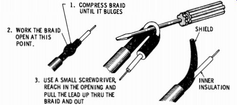
Fig. 16--Technique for stripping shielded
cable.
Hardware
Practically all projects will require some bolts and nuts to mount the various tube sockets, switches, and terminal strips to the chassis.
(Three types of terminal strips are illustrated in Fig. 18.) Two or three sizes of bolts will handle almost any job. The most common size used for assembly in the 6/32 round-head machine screw. You should have a box of these in 1/2- and 3/4-inch lengths. It is also good to have some 4/32 screws in 1/4-inch length for mounting small tube sockets. For both of these screw sizes you need nuts and lock washers. The latter are always placed under nuts to prevent them from working loose. You should also have a stock of 4/32 and 6/32 solder lugs. These can be used in place of lock washers when you want a good ground connection to the chassis for your wiring.
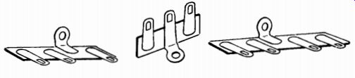
Fig. 17--Terminal strips are available in many different configurations. The
center strip has one lug connected to Mounting bracket so that it can be used
as a chassis ground.
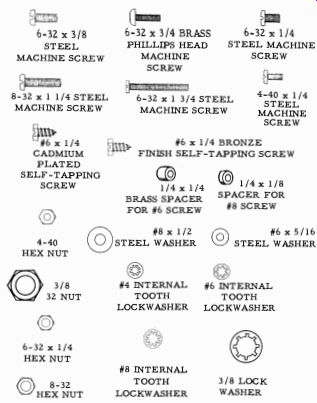
Fig. 18--Common pieces of hardware used to assemble electronic equipment.
An assortment of flat washers to fit your basic screw assortment is also useful. They will take up space in a hole that is too large for the screw head and they will help the screw to fit loosely in the hole to permit some adjustment of position. Flat washers can also be used as spacers to bring a component to a desired height.
A grommet is another hardware accessory that has many uses. This is a circular piece of rubber that can be fitted into any hole in the chassis through which wires pass. The grommet prevents the sharp edges of the hole from cutting into the insulation of the wire. Grommets should always be used at the point where the power cord passes through the chassis.
Because a 3/4-inch rubber grommet will fit tightly around a pilot light bulb, it can be used as a quick mount for a pilot light. A grommet can also be used to insulate a bolt from the chassis. Drill a hole in the chassis, insert the grommet as an insulator, and insert the bolt with a flat washer on either side of the grommet.