AMAZON multi-meters discounts AMAZON oscilloscope discounts
EVERY ELECTRONIC project you will build is made up of a number of parts, or components, hooked together in order to achieve the desired operation of the equipment. These components include tubes, transistors, resistors, capacitors, transformers, chokes, and coils. To do a good job on any electronic project, you should know what these parts look like, how they are used, and the various codes used to identify them.
Each electronic component is given a schematic symbol in a circuit diagram to identify it and show how it is connected into the circuit.
In a later section we will analyze a circuit diagram of a simple radio and see how these symbols are used in the construction of the equipment. Here we will look at the parts represented in the circuit diagrams.
Tubes and Transistors
The tube, or the transistor, is the main part of any electronic circuit. This is the device that provides amplification; that boosts a tiny signal from almost nothing to enough power to drive a loudspeaker.
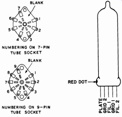
Fig. 19; Fig. 20-Subminiature tube.
In tube circuits, most of your work will be done with three major tube types-octal, 7-pin miniature, and 9-pin miniature. These names describe the type of base the tube has. The 7-pin and 9-pin tubes and their socket arrangements are shown in Fig. 19. The octal type, the oldest of the three, has 8 pins with a center post. The center post has a key that will permit the tube to be inserted in only one way. The 7- and 9-pin tubes have no center pin. A gap between the first and last pins makes it impossible to insert the tube in the wrong position. The pin numbers are always counted in a clockwise direction, looking at the bottom of the tube or socket. Pin number 1 is always the pin to the left of the key in an octal socket or the space in a 7- or 9-pin socket.
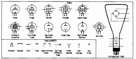
Fig. 21--Symbols for various tube types used by the experimenter.
The octal tube has a plastic base that encloses the lower part of the glass envelope. In the 7- and 9-pin types, the tube is all glass with thin pins projecting from the bottom of the glass envelope. Most new tube designs are of the 7- or 9-pin variety. However, the octal tube is still around, and probably will be for a long time to come.
One other type of tube is the subminiature tube. This is a small, flat tube with five wire leads in a row at the base. It is mounted in a special socket (see Fig. 20). These tubes are popular in hearing-aid, miniature-radio, and radio-control applications where their small size and low battery-current requirements are valuable.
Every tube is made up of two or more elements. These elements include the cathode, plate, and one or more grids (see Fig. 21). Tube-type names are given according to the number of elements in the tube.
A tube with two elements (cathode and plate) is called a diode. With a grid added, it is a triode. A second grid makes it a tetrode, and a third grid turns it into a pentode. Some special-purpose tubes have as many as five grids.
Although these are the main types of tubes you will encounter, there are many other types that are designed for special purposes such as transmitters, ultra-high frequency circuits, and the like. When you come across these in a construction article, there will generally be special instructions to guide you in their use.
To save space and simplify circuit construction, many tubes are actually two or more tubes inside the same glass envelope. These multi unit tubes may consist of two diodes, two triodes, a triode and one or two diodes, or any other combination. When both units are of the same type they are called twins. A twin diode or twin triode in a circuit will perform the same job as would two separate tubes.
Magic-eye tubes are familiar to most people as the tuning indicator in radios. These tubes are often multi-unit types with a built-in triode amplifier for the signal that controls the magic eye. The symbol for a magic-eye tube is shown in Fig. 22. These tubes are frequently used in experimenter's projects and can be the basis of inexpensive test equipment such as is described in Section 8.
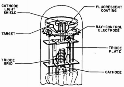
Fig. 22-Cross-section of a magic-eye tube.
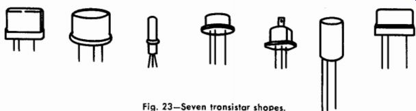
Fig. 23-Seven transistor shapes.
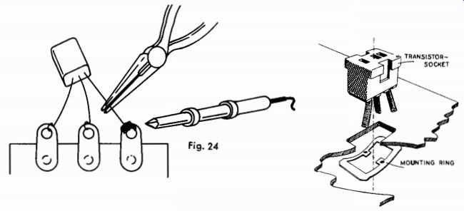
Fig. 24/25-Transistor socket mounted on a chassis by a metal clip that fits grooves
in side of socket.
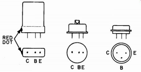
Fig. 26-Three placements of transistor leads.
Transistors are made in a variety of shapes, some of which are shown in Fig. 23. The majority of transistors have only three leads as compared to the seven, eight, or nine on a tube. There are four-wire transistors, but these are not too common and ate used mainly in high frequency circuits. Because transistors have an extremely long life, they can be soldered right into a circuit in a manner similar to the soldering of a resistor or capacitor. However, transistors are very sensitive to temperature and can be ruined by too much heat during soldering. To body (see Fig. 24). The metal will conduct heat away from the transistor and prevent any damage.
An easier way to avoid heating troubles with transistors is to use transistor sockets. These sockets are similar to those used for subminiature tubes and have three or four holes to receive the transistor leads.
A typical socket is shown in Fig. 25. The sockets are installed in a rectangular hole cut in the chassis, and a spring metal clip is used to hold them in place.
The three leads of a transistor are called the emitter, base, and collector leads. These leads are identified in a number of ways by different manufacturers. Some makers indicate the collector with a red dot on the side of the transistor. Others put the emitter and base leads close together, with a wider space between them and the collector. An other way of identifying the leads is to place them in a triangular pat tern. When this type of transistor is held with the base lead at the top of the triangle, the emitter lead is on the left and the collector is on the right. All of these arrangements are illustrated in Fig. 26, avoid damaging a transistor place a pair of pliers or tweezers on the wire you are soldering between the soldering point and the transistor There are two main types of transistors, the PNP and NPN. (These letters indicate the type of germanium used to make the transistor.) They are the electrical opposite of each other. In a PNP type transistor, the collector is connected to the negative side of the battery. In an NPN transistor, the positive side of the battery is connected to the collector.
If two transistors are otherwise identical, a PNP can be replaced by an NPN simply by reversing the battery connections.
As with vacuum tubes, there are many different types of transistors.
Some are only suitable for audio frequencies, others for low radio frequencies, and still others for high frequencies.
The power transistor is a recent development that holds much promise for the experimenter. This unit will handle enough electrical power to drive a loudspeaker at high volume. As can be seen in Fig. 27, the construction of a power transistor is quite different from that of a conventional transistor. To remove the heat created by the large current passing through the transistor, a heat sink must be used. The body of a power transistor is large in order to provide a large surface to contact the chassis. This conducts the heat away from the transistor to the chassis. A power transistor has only two leads coming from the body. One of these is the emitter lead; the other is the base lead.
The collector connection is made directly to the metal body. Because this terminal usually is not connected to the ground, an insulator must be installed before bolting the transistor to the chassis. A thin sheet of plastic material or mica can be placed between the transistor and the chassis and the collector connection can be made to the body of the transistor.
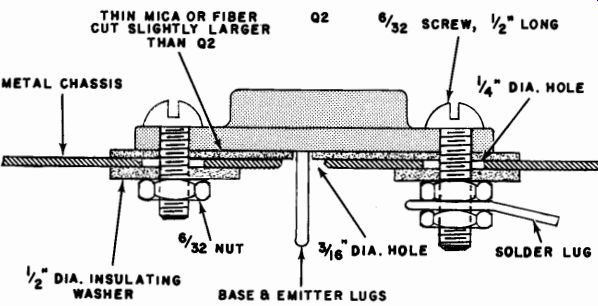
Fig. 27--Construction diagram of the mounting of a power transistor when the
collector must be insulated from the chassis.
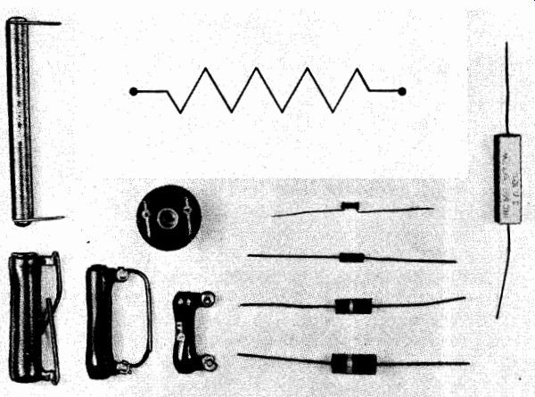
Fig. 29----- Crystal diodes are made from the same material as a transistor. They will perform the same function as a vacuum-tube diode does; just as a transistor will perform the functions of a vacuum-tube amplifier. The various types of crystal diodes are shown in Fig. 28. Crystal diodes are sensitive to heat, and the same precautions should be taken as are taken with transistors.
In working with transistors and diodes in experimental circuits, use two or three lug terminal strips as mountings for the transistors or diodes. All connections for the transistor can be made directly to the lugs and then, as the final step in construction, the transistor leads can be soldered to the lugs. This technique provides a firm mounting for the unit and decreases the possibility of damaging the transistor each time a lead is soldered. Use a pair of pliers on the transistor leads while soldering in order to prevent heat from the soldering iron from reaching the transistor body.
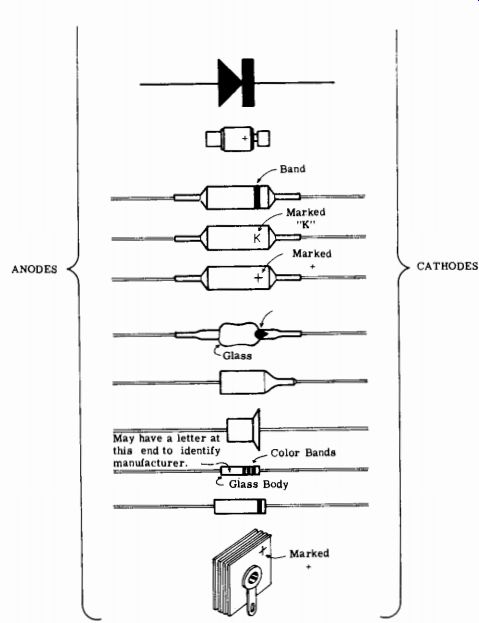
Fig. 28- Crystal diodes and rectifiers are marked in many ways. The symbol for
all types shown here is at top.
Fig. 29--Fixed resistors are indicated by symbol at top center. The units
shown at left are wire wound; those at center ore of a carbon composition.
The rectangular unit at the right is a 7-watt resistor used in power-supply
circuits.
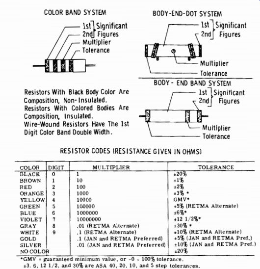
Fig. 30-Resistor color codes. Resistors With Black Body Color Are Composition,
Non-Insulated.
Resistors With Colored Bodies Are Composition, Insulated.
Wire-Wound Resistors Have The 1st Digit Color Band Double Width.
Resistors and Capacitors
Resistors and capacitors are the most commonly used component in electronic circuits. For each tube or transistor used in the average circuit, there are about four or five resistors and two or three capacitors.
Resistance is the opposition that a unit will offer to the flow of current and is measured in ohms. The schematic symbol for a resistor is a zig-zag line (as shown in Fig. 29). Values of resistors used in electronic circuits range from a few ohms to many millions of ohms. To simplify the writing of large numbers, abbreviations are used. A "K" following a number means that you multiply that number by a thou sand. An "M" or "meg" following a number means multiply by a million. For example, a resistor rated at 250,000 ohms could also be labeled as 250K or 0.25 meg. All have the same value of resistance.
The value of a resistor is either stamped on the side in numbers or indicated by colored bands in the standard resistor color code. In order to read this code, you must know the numbers that the colors indicate.
These are shown in Fig. 30. The first .two bands indicate the first two numbers of the resistance value. The third band indicates how many zeros follow the two numbers. For example, suppose that we have a resistor with a blue, a grey, and an orange band. Looking at the chart, we find that blue is 6 and grey is 8. Our first two numbers are 68. The third band shows that we must multiply these numbers by 1,000 to get the total value. Our resistor is 68,000 ohms or 68K.
The tolerance rating of a resistor is another important piece of information for the experimenter. The tolerance is the amount (in percent) that a resistor can vary from the specified resistance value.
For example, a resistor with a specified value of 100,000 ohms, 10 percent tolerance, may actually range in value from 90,000 ohms to 110,000 ohms. Resistors are available in 1, 2, 5, and 20 percent tolerances. In most circuits the 20 percent tolerance is good enough, and this is the one that should be used, because the price of resistors goes up as the tolerance becomes closer. In some critical circuits, the closer tolerance resistors are required. If a close tolerance resistor is specified by the author of a construction article, it should always be used. Tolerance is usually indicated on a resistor by a fourth colored band. If there are only three bands on a resistor, tolerance is 20 percent. If the fourth band is silver, tolerance is 10 percent; if it is gold, tolerance is 5 percent. These are the most common tolerances in use. The colors for other resistor values are given in the resistor code chart.
Familiarity with tolerance ratings can be valuable to the experimenter because he can often use this information to substitute a resistor he has in stock for one that he would have to buy. Suppose a circuit calls for a 220,000-ohm resistor with 20 percent tolerance. Its actual value can range from 176,000 to 264,000 ohms. You could substitute a 240,000-ohm or a 200,000-ohm resistor for the specified unit, providing the substitute has a 10 percent tolerance. Similarly, a 47,000-ohm resistor can be substituted for a 50,000-ohm unit, and vice versa.
An experimenter should know the wattage rating of resistors. This is the resistor's ability to handle power without overheating. In most small resistors, wattage rating is determined by the size of the unit, and no indication is given. The most commonly used size is the 1/4-watt resistor which is about 3/5 inch long and 1/2 inch in diameter. The next size is a 1/2-watt resistor, about 1/2 inch long and V4 inch in diameter.
A 1-watt resistor is about 1 inch long and 3/8 inch in diameter. Larger wattage resistors, often used in power supplies, are usually stamped with the wattage rating.
A higher wattage resistor can be used in place of a smaller wattage unit if there is enough room on the chassis. If a circuit calls for a 47,000-ohm 1/2-watt resistor, you can substitute a 1/2-, 1-, or even 2- or 5-watt resistor of the same resistance value if you don't have a 1/2-watt unit on hand.
Potentiometers
Another resistor that the experimenter often encounters is the variable resistor. There are two types of these variable resistors-continuously variable (rheostats and potentiometers) and semi-fixed adjust able. As shown in Fig. 31, the latter type has movable taps which, once set, are left in position.
Both of these types of variable resistor are rated in exactly the same way as fixed resistors are rated, but the continuously variable type has an additional specification that can be confusing, especially because these units are widely used as volume and tone controls. This additional specification is the taper of the potentiometer.
Taper is an indication of the way that the resistance changes as the control knob is turned through its range. For example, if a potentiometer of 500,000 ohms total resistance measures 10 percent of this value (50,000 ohms) when the control is turned 10 percent of its rotation, 20 percent (100,000 ohms) at 20 percent rotation, 50 percent at 50 percent rotation, and so on, the control has a linear taper.
There are about half a dozen standard tapers in use, but the linear and audio tapers are the most important in electronic work. When a potentiometer has an audio taper, its resistance variation with rotation follows a logarithmic curve. This type of curve follows the curve of your ear's sensitivity to the loudness of a sound. The control used here is the same as that used as a volume control in amplifiers and radios. If a control with a linear taper is used as a volume control, the volume seems to jump from zero to maximum with relatively little rotation control.
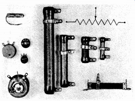
Fig. 31-Variable resistor types. Potentiometers are on wire-wound types which
have an adjustable tap are on the right.
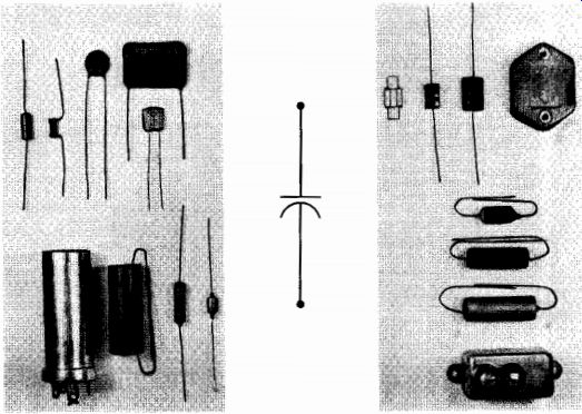
Fig. 32-Various shapes and sizes of fixed capacitors. Capacitor symbol is
shown at center. Unit at lower left is can-type electrolytic.
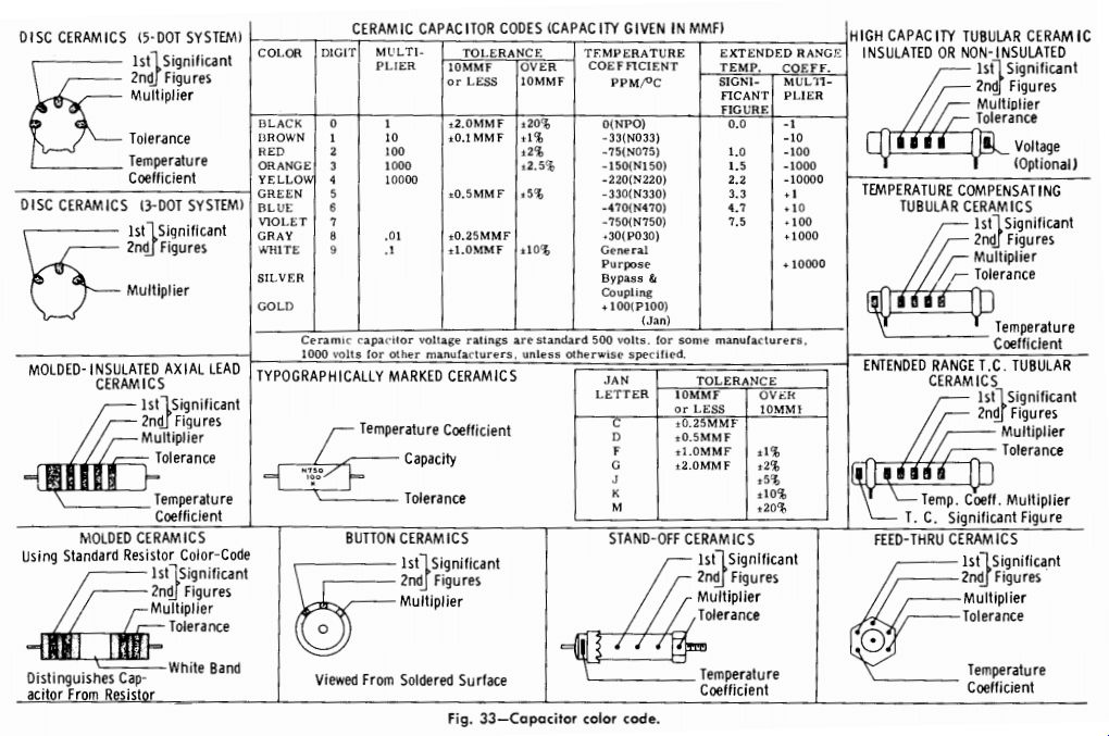
Fig. 33-Capacitor color code. DISC CERAMICS (5-DOT SYSTEM) CERAMIC CAPACITOR
CODES (CAPACITY GIVEN IN MMFI
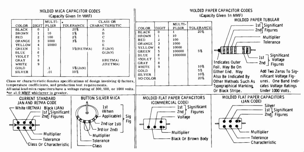
Fig. 33-Capacitor color code (continued).
Capacitors
A capacitor is made up of two closely spaced conductors (such as metal foil) with an insulator between them. Its schematic symbol shows these two conductors as plates, with a gap between them. Some of the different types of insulation material used are glass, air, plastic, mica, chemical films, and oils. Typical units are shown in Fig. 32.
There are three important types of specifications given for capacitors. These are capacitance, tolerance, and voltage rating. The values are usually stamped on the side of the capacitor. For some types, a color code similar to that for resistors must be used. These codes are given in Fig. 33.
Capacitance is given in microfarads (ufd) or in micromicrofarads (u-ufd). A micro-microfarad is one millionth of a microfarad. Typical values for capacitors range from a fraction of a micro-microfarad to as high as several thousand microfarad, depending on the circuit application. Microfarads and micromicrofarads are often used interchangeably.
A capacitor can be marked either 0.005 ufd or 5,000 u-ufd and be of the same value. Sometimes, the letter "m" is used to indicate micro.
Except in critical circuits, the tolerance rating of a capacitor is not as important as a resistor's tolerance.
Most capacitors have a tolerance rating of about 20 percent, although some bypass and filter capacitors may have dual ratings, given as -10 percent, +50 percent.
This means that the actual value may range from 10 percent below rated value to 50 percent above rated value.
A capacitor's voltage rating indicates the maximum voltage that can be applied without breaking down the insulation material and causing a short circuit to occur between the two conductors. Most capacitors are rated with the direct current working voltage (DCWV or WV), which is the average steady voltage that can be applied to it.
On some capacitors, the peak voltage is also given.
Capacitors are made in a wide variety of shapes, some of the more common types are the tubular, "postage stamp" mica, disc ceramic, or "bathtub" types.
Electrolytic capacitors, usually used in filter circuits, have a very large capacitance for their size. The connection leads of an electrolytic are always marked with a plus or minus sign to indicate how they are connected to the circuit. The positive lead (+) is always connected to the positive side of the circuit. In "can" capacitors, the outer metal is usually the negative (- ) terminal of the unit.
Most paper tubular capacitors are put together by rolling up a sandwich made of two pieces of metal foil with paper between them.
Thus, one foil will be on the outside of the completed roll. This lead is identified by the words "ground" or "outside foil" or by a ring around one end of the capacitor. It is good construction practice to connect this lead to the ground side of the circuit. When this is done, if the outer covering of the capacitor should be worn away or cut by rubbing against the chassis, the foil exposed would be at the same voltage as the chassis.
Variable capacitors (see Fig. 34) are of two general types-those designed for continuous adjustment with a control knob and used as a tuning capacitor and those designed for semi-fixed adjustment with a screwdriver. The latter are called trimmer capacitors if their values are small (up to, say, 100 u-ufd) and padder capacitors if their maximum value is fairly large (up to 1,000 u-ufd). Both classes are rated as to minimum or maximum capacitance.
Tuning capacitors have a fixed set of plates, called the stator, and a variable set of plates, known as the rotor. Air is generally used as the insulating material between the plates, except in small sizes, where thin sheets of plastic may be used. Often, two or more tuning capacitors can be "ganged" together for operation on a single shaft. Each section may have its own trimmer to adjust for minor differences in minimum capacitance.
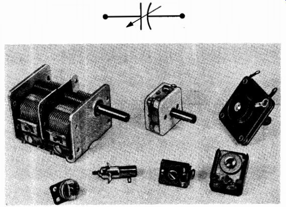
Fig. 34-Variable capacitors. Trimmer and padder types are at bottom.
Trimmer and padder capacitors use thin sheets of mica, ceramic plastic, or glass as the insulator between plates.
In most cases, the two most important characteristics of a fixed capacitor are capacitance and working voltage. Except in filter circuits, the capacitance should be as specified in the original circuit. Working voltage should be equal to or greater than that specified. The type of capacitor is not too important.
For example, if a 0.002-ufd disc ceramic is specified for a particular circuit, a 0.002-pid tubular ceramic, mica, or paper capacitor of comparable working voltage will work just as well in all but some high-frequency circuits.
If space permits, you can always use a capacitor with a higher working voltage than that specified. If a 0.01-pid, 150-volt capacitor is called for, you can use a unit rated at 200, 400, or even 600 volts. Never use one rated at a lower working voltage than that specified.
Some alternative symbols used for capacitors are shown in Fig. 35.
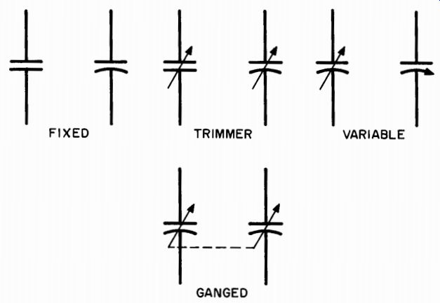
Fig. 35-Symbols for capacitors.
Transformers
Basically, a transformer consists of two or more coils of wire wrapped around a core. In the schematic symbol, the input (primary) and output (secondary) windings are shown on either side of the core, as in Fig. 36. If the core is air, nothing is shown between the coils. If it is an iron core, two or three straight lines are drawn between the coils. As with resistors and capacitors, an arrow through the core or one of the coils indicates adjustability. Antenna coils, which are really an air core transformer, can be mounted either by a simple bolt or can be plugged into a base. Power transformers and output transformers are always mounted on brackets above the chassis or in a cut-out hole in the chassis. The first method is preferred by most experimenters because it requires only drilling mounting holes. A common type of transformer used in radio is the i.f. transformer.
This unit requires a special mounting bracket such as is shown in Fig. 37. After the hole is made in the chassis, the clip is inserted and pushed into slats in the side of the transformer.
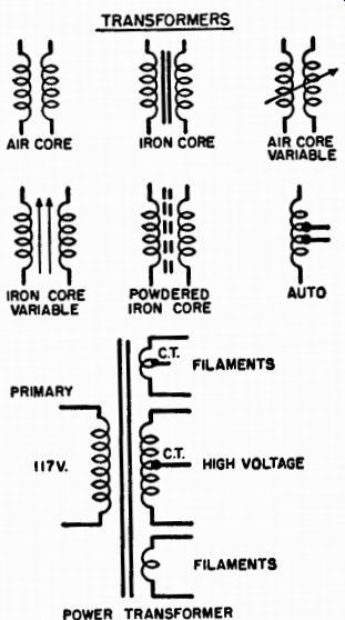
Fig. 36--Transformer symbols.
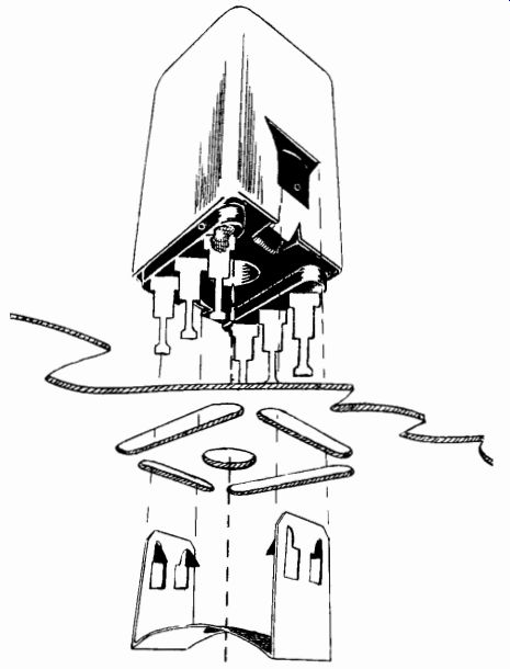
Fig. 37--Transformer mounting. Spring clip fits notches in side of can.
Identifying the leads on transformers can be quite a problem for the experimenter. Most air-core coils use enamel-covered wire, so color coding the wires cannot be used. The manufacturer usually supplies a diagram of the transformer with each new unit, but if you have lost this or are using an old transformer, it is necessary to figure out the wiring. The schematic diagram of the circuit you are building will indicate the longer and shorter windings of the coils by the relative length of the coil symbols. After you have wired the coils according to their length, try the unit out. If it doesn't operate, reverse the connections on one of the coils.
It is much easier to determine which wire is which in power trans formers. The color code is as follows: Power leads for 110-volt line are black. B+ leads are red, with the center tap of that winding red and yellow. The tube filament winding is yellow, and the filament winding (if any) for the rectifier is white. Output transformers use a similar code with brown and blue for the two input leads and black for the ground side of the output. On some transformers, the output leads are not color coded, but are easy to identify because they are small size enamel or cotton-covered wires. If there is a centertap on the primary of an output transformer, it is color coded red.
Connections to i.f. transformers are made to lugs on the bottom of the unit. These lugs are numbered and the No. 1 lug is indicated by a dot of colored paint on or near that lug.
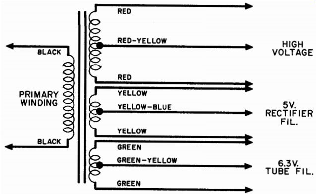
Fig. 38--Wire color coding for typical power transformer.
Where to Get Parts
There are two main sources of parts for the electronic experimenter.
The first, and most economical, is the junk box. Every good experimenter should have one. Spreading the word around will produce many friends who are only too willing to give you their old radios and TV sets just to get rid of them. When you get a set home, first remove all the tubes and put them in a safe place where they won't get smashed. Next, get under the chassis and start clipping out resistors, capacitors, coils, and any other part that looks useful. When you are cutting out components try to cut the wire leads as far from the part as possible. This will make them more useful in future projects. Then, sort out the parts, placing all resistors in one box, capacitors in another, etc.
The second source of parts is your local radio parts house. Here you will find all of the components you will need for any project.* Free catalogues are available and will provide you with a handy source of price information so that you can estimate the cost of a particular project.
* Mail order companies such as Allied Radio, Radio Shack, Lafayette, Newark, and Olsen Radio provide extensive catalogues of parts. Because these companies do a nation-wide business, they often have parts that are not readily available at your local store.