AMAZON multi-meters discounts AMAZON oscilloscope discounts
THE PROJECTS in this section have been selected as units sure to work when properly constructed.
They require varying degrees of building skill-the beginner may find some that will give him practice; the more advanced worker may find some that challenge his electronic skills.
Amplifiers and AM radios are generally easy projects with which to start.
Do not work with miniaturized transistor equipment until you have developed sufficient skill with a soldering iron to work in tight places.
Low-cost Broadcast Receiver
All of the parts for this simple, two-tube receiver are probably available in the junk box of an average radio experimenter.
Coil L1 is a Feri-Loopstick.
Tuning capacitor C2 can be any high-capacity variable salvaged from a junked AM receiver. Filament-dropping resistor R7 can be a single 500-ohm, 20-watt resistor or a pair of 10-watt, 1,000-ohm resistors in parallel.
The circuit uses a 12AT7 (V1) as a detector and audio amplifier, and a 35W4 serves as a half-wave rectifier. Although the grid leak detection method may add some distortion in very strong signal areas, the sensitivity is much greater than that obtained with crystal diode detectors.
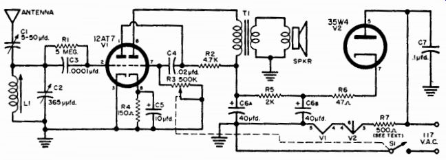
Fig. 137--Schematic for low-cost receiver. A 12AU7 can be used in place of
the 12AT7 if it is easier to obtain.
Remember that this is an a.c. / d.c. receiver and that care must be exercised in grounding the chassis. Keep the chassis away from water pipes and outside electrical grounds.
The antenna can be any length of wire. Using only 6 feet of antenna, stations 500 miles away were pulled in at night. The local stations were quite strong during the daytime.
After the antenna is connected, tune in a very weak station near the minimum capacity of tuning capacitor C2. Then adjust the core in the Feri-Loopstick for maximum volume.
PARTS LIST
C1-5-50-µfd. variable capacitor
C2-365-µ-µfd. variable capacitor
C3-0.0001-µfd. mica capacitor
C4-0.02-µfd., 400-volt paper capacitor
C5-10-µfd., 25-volt electrolytic capacitor
C6a/C6b-40-40 ufd., 150-volt electrolytic capacitor
C7-0.1-µfd., 400-volt paper capacitor
L1-Feri-Loopstick
R1-5-megohm, 1/4-watt carbon resistor
R2-4700-ohm, 1/2-watt carbon resistor
R3-500,000-ohm volume control potentiometer
R4-150-ohm, 1/2-watt carbon resistor
R5--2000-ohm, 1-watt carbon resistor
R6--47-ohm, 1-watt carbon resistor
R7--500-ohm, 15-20 watt wire-wound resistor
S1--S.p.s.t. switch (on R3)
SPKR-PM speaker
T1-Output transformer, 4000-ohm primary, 3.5-ohm secondary
V1-1 2AT7 tube
V2-35W4 tube
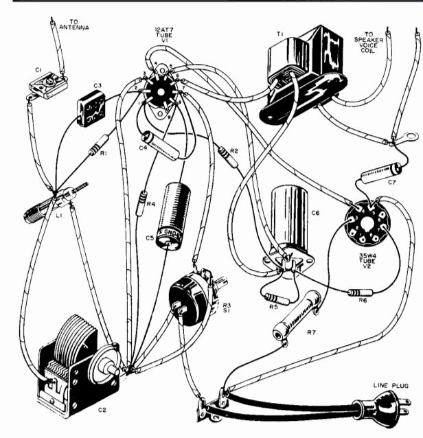
Fig. 138-Interconnect components as shown.
Resistor
R7 will get warm in normal operation.
One-tube Hi-Fi AM Tuner
Fig. 139--Compact AM tuner can be used for stereo channel in AM/FM stereo
setup.
This unusually compact, inexpensive broadcast-band AM radio tuner is useful for the AM channel of AM/FM stereo listening. As a solo performer, it will bring new life into AM broadcasts played through your hi-fi rig.
Completely sell-contained, and with its own transformer-type a.c. power supply, the unit has as wide a frequency response as AM stations transmit. It introduces no distortion in its detector stage and uses so little power that you can expect operation for many years without trouble or breakdown. A stage of r.f. amplification and the two tuned stages of iron-core high-Q coils cover the whole broadcast band with sensitivity and selectivity.
The entire tuner is constructed on a 5 1/4-inch by 3-inch by 2 1/8-inch chassis. Needless to say, the cost of this "one-evening project" is quite low.
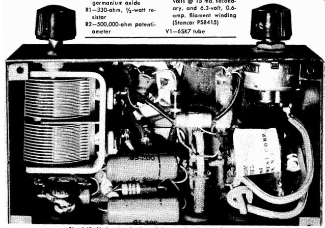
Fig 140--Under-chassis view of the completed tuner shows parts placement.
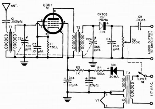
Fig. 141--Note the use of the power transformer to connect the tuner to any
amplifier.
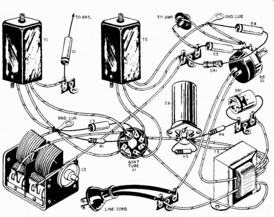
Fig. 142--Follow the pictorial diagram for best results in building the tuner.
PARTS LIST
C1-0.005-µfd., 600-volt capacitor
C2a/C2b-365-365 ufd., 2-gang, TRF-type tuning capacitor
C3-0.01-ufd., 400-volt capacitor
C4-250-µfd. mica or ceramic capacitor
C5-0.01-200-volt capacitor
C6a/C6b-20-20 150-volt dual electrolytic capacitor
CR1-1N34A or CK705 germanium oxide
R1-330-ohm, 1/2-watt resistor
R2-500,000-ohm potentiometer
R3-1000-ohm, 1-watt resistor
R4-100-ohm, 1/2-watt resistor
S1-S.p.s.t. switch (on R2)
SR1-20-ma., 130-volt selenium rectifier
T1-Antenna coil (Miller A-320-A)
T2-Detector coil (Miller A-320-RF)
T3-Power transformer, 117-volt primary, 125 volts @ 15 ma. secondary, and 6.3-volt, 0 6-amp filament winding (Stancor PS8415)
V1-6SK7 tube
An old standard, the 6SK7 tube, is used as an r.f. amplifier and is paired with a 1N34A or CK705 as a tuned diode detector. A selenium rectifier eliminates the need for a tube in the power supply.
Antenna length is not critical-use a long enough wire to give adequate audio signal output. A volume control with an on-off switch is shown in the photos and diagrams; this can be eliminated if the high fidelity amplifier to which the tuner is connected already has one.
V.H.F. Explorer's Receiver
Fig. 143--You can tune in on many new listening pleasures with the v.h.f. explorer's
receiver.
Exploring the many services using the v.h.f. band will furnish you with real listening excitement. Not only are the familiar FM and TV broadcasting services found in this region, but there are also a host of others, such as: Police, Fire, Public Utilities, Taxi, Aircraft, Amateur, etc.
The Explorer's Receiver has three plug-in coils and will pick up all these services in the range of 28 to 175 mhz. The receiver has excellent sensitivity, although it uses only two tubes. This is accomplished by using a super-regenerative detector. This detector circuit has long been famous for its sensitivity, as well as for some of its less desirable traits. A super-regenerative detector is basically an oscillator.
Therefore, it's only natural that it cause interference. In this receiver the problem is overcome by preceding the detector with an r.f. isolation stage.
PARTS LIST
C1-0.001-µfd. tubular ceramic capacitor
C2a/C2b/C2c-20/40/20 ufd., 250-volt electrolytic capacitor (Cornell-Dubilier Type BBRT 4225C)
C3-7-pfdd. tubular ceramic capacitor
C4-0.33-ufd., 200-volt paper capacitor
C5-3.044 0d. to 22.5440d. v.h.f. capacitor (National Type VHF-1-S)
C6-0.004-ufd. tubular ceramic capacitor
C7-25--µufd. tubular ceramic capacitor
C8-0.01-pfd. disc ceramic capacitor
11-Open-circuit jack
11-3 coils
R1, R3-330-ohm, 1/2-watt resistor
R2-5600-ohm, 1-watt resistor
R4-47,000-oh m, 1/2-watt resistor
R5-7.5-megohm, 1/2-watt resistor
R6-25,000-ohm potentiometer
R7-2200-ohm, 2-watt resistor
RFC1, RFC2-Z50 Ohmite choke
RFC3-25-mh. Choke
RFC4, RFC5-Z144 Ohmite choke
S1-S.p.s.t. toggle switch
SR1-65-ma., 160-volt selenium rectifier
T1-Power transformer, sec. 150 volt, 25 ma.; 6.3 volt @ 0.5 amp. (Stancor P8181)
T2-Audio transformer, interstage 1:3 ratio (Stancor A-53)
V1-12AT7 tube
V2-6AF4 tube 1-Crystal socket (Miller No. 33102) 1-6" x 6" x 6" cabinet (LMB)
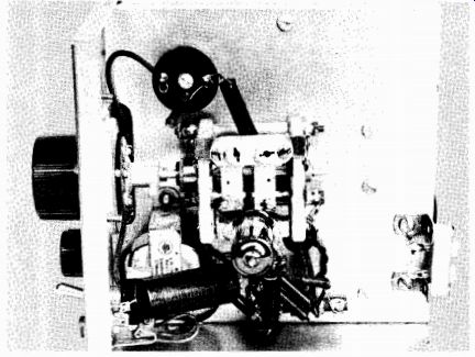
Fig. 144--Interior view of left side of the receiver showing location of power-supply
components and the combination r.f. and audio-amplifier tube.
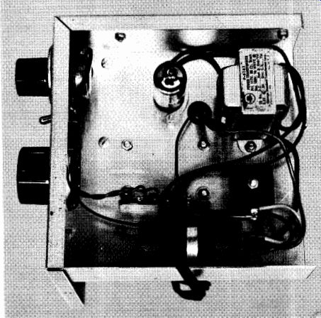
Fig. 145--Right side of receiver contains oscillator tube and coil socket
into which band coils are plugged. Point-to-point wiring and short leads are
used.
This receiver requires some care in building. The lengths of the leads play an important part in successful operation. For this reason, it is recommended that the photographs of the receiver be carefully studied. If possible, copy the parts layout exactly.
The receiver itself is constructed in a 6-inch by 6-inch by 6-inch box in which the chassis is mounted vertically. There is a good reason for this unorthodox approach. It permits very short leads between the antenna input and the detector. Note that the r.f. stage is mounted horizontally from one side of the chassis so that the bottom of the socket will face the 6AF4 socket.
The detector tube socket is mounted on the variable capacitor C5, which is made specifically for this application and has brackets for mounting a tube socket. The coil socket is a ceramic (or other high-quality material) crystal socket. All sockets, couplings, and capacitors used in the r.f. and detector stages should be of similar high-quality material.
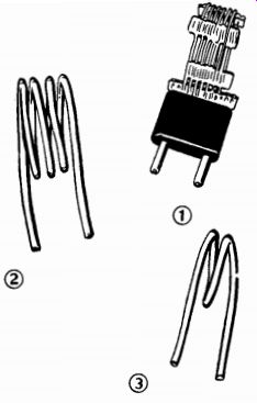
Fig. 146 (1)-For the 28-50-mc band: six turns of Barker & Williamson Miniductor
No. 3015 coil stock (16 turns/inch), soldered into Millen No. 37412 plug. (2)-For
the 48 to 90-mc band: four turns of No. 12 wire, tinned, 1/2" long, 1" in
diameter. (3)-For the 90-175-mc band: two turns of No. 12 wire, tinned, 1/2" long,
3/4" in diameter.
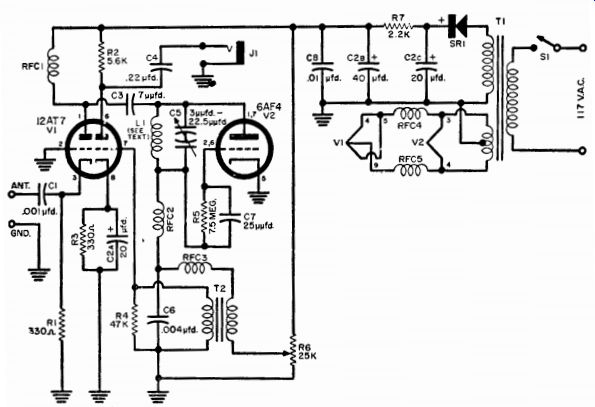
Fig. 147--Schematic for v.h.f. receiver.
The National VHF-1-S tuning capacitor C5 is different from the type of variable capacitor commonly used at lower frequencies. There are two stators and two rotors, but the capacitor wiring terminals are connected to the two stators while the rotors are fastened to a common shaft. Thus, two variable capacitors are effectively placed in series.
The power supply section is located on the chassis opposite the r.f. wiring.
Before the unit is assembled, the cabinet will need a large hole cut through the side to comfortably allow the plugging in of the three coils.
The hole in the model shown is 1 1/4 inches by 2 3/8 inches.
After the receiver is completed, including the coils, turn on the a.c. switch, and advance the regeneration control R6 until a loud hissing sound is heard in the headphones. Now tune the receiver for a signal always remember to adjust the regenerative control for the proper level.
The last step is to calibrate the three bands. If you have access to a signal generator, this is no problem. It becomes more difficult, but not insurmountable, if no signal generator is available. Generally there are enough signals of known frequency, such as TV and FM stations, to allow you to make a rough calibration.
There is no single antenna that will produce top performance over the complete range covered by the receiver. An outdoor TV antenna will perform fairly well. However, this type of antenna is directional and horizontally polarized. Most mobile services use vertically polarized antennas. For general listening, a plain random-length piece of wire does as well as anything.
For top performance, a dipole cut to the desired frequency will produce superior results. The antenna can then be hung vertically or horizontally.
Printed-circuit Transistor Receiver
With a power consumption of about 1 milliwatt, and using the new miniature dynamic earphones, this receiver will deliver earsplitting volume on local stations. A little more than half the size of a king-size pack of cigarettes, its power supply is a single 1.3-volt mercury cell which is called on to supply about 1 milliampere of current at full volume. It needs no external antenna, although one can be employed in low-signal areas.
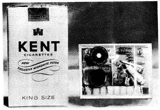
Fig. 148-Complete transistorized receiver.
PARTS LIST
B1-1.3-volt mercury cell (Mallory RM-630)
C1-365-Lifd., single-gang, midget variable capacitor (Argonne Poly-Vari-Con)
C2, C5- 0.01 ufd., subminiature capacitor (Aerovox P832)
C3- 0.0005 ufd., subminiature capacitor (Centralab DM-501)
C4-30-ftfd., 6-volt electrolytic capacitor
C6, C7, C8-8ufd., 6-volt electrolytic capacitor .11-Miniature jack (Telex 9240) 11-50 turns of #22 s.c.e. wire on 1/4" x 2%" ferrite core (Lafayette MS-331)-see text L2-Six turns #22 s.c.e. wire on same core L3-R.f. choke (winding from a discarded miniature i.f. transformer) PC1, PC2-XXXP printed-circuit copper laminated board (one 2" x 4t/4" section cut in two parts-1' Vie" x 2 1/16" far
PC1 and 11146" x 2546" for. PC2) R1-100,000-ohm resistor, 1/2-watt resistor R2-15,000-ohm, 1/2-watt resistor R3-5600-ohm, 1/2-watt resistor R4-25,000-ohm subminiature volume-re generation potentiometer (Lafayette VC-45)
R5, R6-22,000-ohm, 1/2-watt resistor
S1-S.p.s.t. switch (on R4)
TR1-CK768 transistor
TR2, TR3, TR4-CK722 transistor 1-6-az. bottle of etching solution (Lafayette PE3)
1- Roll of resist-tape or ball-point tube (Lafayette PRT-3 or PRTL) 12-"Flea" clips for soldering contacts
Misc. eyelets (0.062" in diameter by 0.093" long); tin, copper or brass for battery holder; plastic cabinet
Two printed-circuit boards (PC1 and PC2) are used (see parts list). Cut out the laminate to sizes shown in templates in Fig. 149.
These can be made as described in Section 5. The width of the conductor strips should be about 1/16 inch, and the connection points should be about 0.25 inch in diameter.
Drill the holes for mounting the components. All are made with a 1/16-inch drill, except the mounting holes for the tuning capacitor (C1) Two of these holes are 1/8 inch in diameter and are countersunk from the non-etched side of the board. The hole for the shaft of the same capacitor is 1/4 inch in diameter and is countersunk from the etched side of the board. Although the flea clips are intended to be mounted in 1/2-inch holes, it is better if only the smaller bottom part is fitted into the 1146-inch holes.
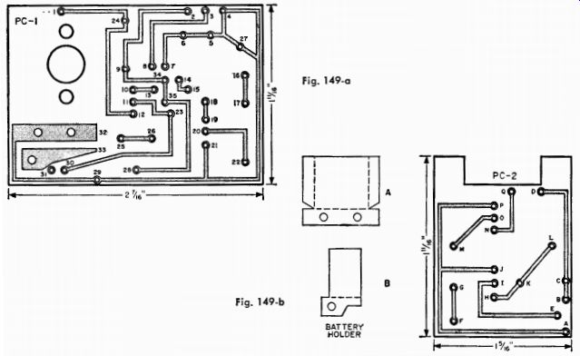
Fig. 149-a; Fig. 149-b
CONNECTIONS FOR PC1
1-Top of antenna coil
2-Bottom of antenna coil
3-Top of tickler coil
4-Bottom of tickler coil
5 and 15-R3
6 and 14-05
7 and 34-C2
8 and 13-C3
9-Top terminal of C1
10-Emitter of TR1
11-Base of TR1
12-Collector of TR1
13 and 15-L3
16 and 18-R5
17 and 26-Jumper wire
18-2" wire to G of PC2
19-Collector of TR2
20-Base of TR2
21-Emitter of TR2
22-C6 (pos. terminal)
23-C4 (neg. terminal)
24-C1 (bottom terminal)
25 and 31-R1
25 and 35-R2
25-Wire to PC2, Point B
26-S1 (either terminal)
27-C4 (pos. terminal)
28-C6 (neg. terminal)
29-Wire to PC2, Point A
29-Right terminal of R4 (with prongs facing you)
30-R4 (center terminal)
31-Left terminal of R4 (with prongs facing you)
32-Positive terminal of battery holder (Part A)- see text
33-Negative terminal of battery holder (Part B)- see text
33-S1 (remaining terminal)
CONNECTIONS FOR PC2 A--Wire from 29 of PC1 B-Wire from 25 of PC1 C and K-R6 D-Wire to one terminal of J1 E-C7 (pos. terminal) F-C7 (neg. terminal) G-Wire from 18 of PC1 H-Collector of TR3 I-Base of TR3 1-Emitter of TR3 L-C8 (neg. terminal) M-C8 (pos. terminal) N-Collector of TR4
0-Base of TR4 P-Emitter of TR4
0-Remaining terminal of .11
Follow the lists of connections (two numbers or letters indicate that a component should be connected between these two points, and a single letter designates a terminal such as one of the transistor electrodes or a battery terminal) and insert all the components in their respective positions, but do not solder them in as you go along. They are all mounted on the non-etched side of the board with the exception of C1, R1, and the battery holder.
If all parts fit well, solder them in place with a hot, well-tinned, small-tip soldering iron or gun. When soldering the parts in place, always have the transistors in place when soldering the flea clips to the conductors.
Antenna coil L1 is wound on a piece of ferrite core which measures 23/8 inches by 1/4 inch in diameter. This coil consists of fifty turns of No. 22 single cotton enamel wire, and the tickler coil (L2) is made from six turns of the same kind of wire. Wind both coils immediately adjacent to each other and in the same direction; otherwise you will not get positive feedback and the detector will not oscillate.
The battery holder consists of two parts: Part A, the positive terminal, connected at 32; and part B, the negative terminal, connected at 33. Trace the pattern of these parts as shown in Fig. 149 on brass, tin, or copper; then cut them out. Bend them on the dotted line toward you while you hold the parts as shown. Mounting holes for the battery holder are also i/i6 inch in diameter, and terminals are riveted to the board using small eyelets or miniature screws and bolts.
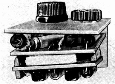
Fig. 150-Side view of the completed assembly. Note the small wooden spacers
glued between the two printed-circuit chassis boards. The three sides and the
bottom of the chassis are installed later.
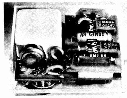
Fig. 151-Chassis with two sides installed. Tuning capacitor and battery are
at left.
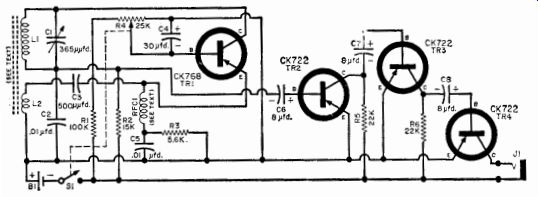
Fig. 152-Schematic diagram of transistorized receiver.
Pieces needed to construct a cabinet can be cut from a clear poly styrene sheet. The front and back of the case shown measures 1 7/8 inches by 2 5/8 inches; the top and bottom are 1 inch by 2 5/8 inches; and the sides measure 1 inch by 1 3/4 inches.
Glue the pieces together temporarily, but leave the back off.
Place the completed receiver inside the case and mark the spots for the shaft of C1 and the regeneration control (R4). Drill a 1/4-inch-diameter hole for the shaft and starting hole of R4. With a 5/8-inch chassis punch, score a 5/8-inch circle in the plastic. Cut out the circle with a jigsaw. Fasten the potentiometer to the panel through the on-off switch tabs.
The box can now be cemented together. Place the radio inside and drill the mounting holes for R4 and earphone jack J1.
Listen to Aircraft with a Miniature v.h.f. Receiver
PARTS LIST
B1-Penlite cell
C1-9- ufd. variable capacitor (Johnson 9M11)
CR1-1N82 v.h.f. diode
J1-Tip plug and jack
J2, J3-Tip jack
L1-4 turns of #16 tinned wire, 3/4" diameter, spaced to 1/2" long
TR1-CK722 transistor (Raytheon)
TR2-2N35 transistor (optional-see text) 1-2" x 2y8" x 1" plastic case
1-Phenolic tie point (Cinch-Jones 53E)
1-Knob, 3/16" shaft 1-16" length of stiff copper wire for antenna
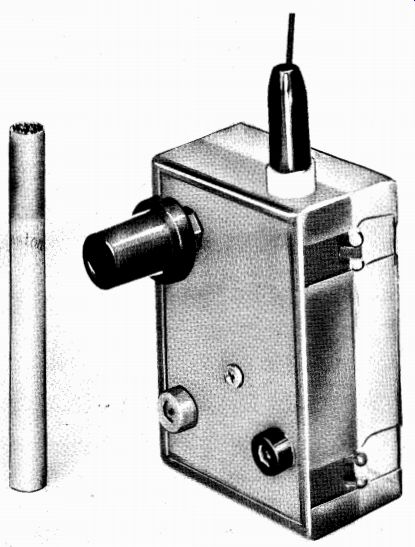
Fig. 153-Aircraft receiver is no higher than a cigarette.
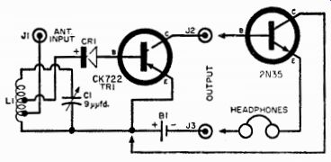
Fig. 154-Schematic diagram of receiver. Headphones can be plugged directly
into output of single transistor, but greater volume results if transistor
TR2 is added and J2 /J3 repositioned in circuit.
If you live near an airport, you can use this receiver to listen in on the control tower talking to aircraft. If you take a flight, you can listen to aircraft talking to the ground control station. You can do all this with the receiver operating in your pocket.
The unit that performs these stunts is shown in the photographs.
It employs a 1N82 v.h.f. silicon crystal diode detector and uses an in expensive CK722 transistor for an audio amplifier. The transistor is powered by one or two 1 1/2-volt penlite batteries.
You can build the v.h.f. receiver in a plastic box measuring ap proximately 2 inches by 27/8 inches by 1 inch (obtainable from a local five-and-ten-cent store). A banana jack atop the box holds a 16-inch length of wire to be used as an antenna. On the front of the box is a tuning capacitor, C1; this is an ordinary 9-micromicrofarad midget capacitor.
At the bottom of the plastic box, the penlite cell(s) is held in place by two short pieces of solid wire, soldered to the ends of the battery.
The negative (battery shell) lead goes directly to the earphone jack above the battery; the positive lead goes to the transistor's emitter terminal. The collector of the transistor is distinguished by a red dot on the case. This terminal of the tie-point strip is connected to the other earphone pin-tip jack.
Wind a simple four-turn coil of No. 16 tinned wire and mount it across the terminals of Cl. The coil is tapped one-half turn up from the end attached to the rotor of C1 and is connected to the emitter of TR1 by another length of short wire.
The last item to be placed in the circuit is the 1N82 v.h.f. diode.
This connects between the base of the transistor and a tap on the tuning coil. Place the tap two turns up from the end of the coil attached to the rotor of C1.
As in the case of the transistor, the 1N82 crystal can be damaged by excessive heat. As you solder each into the circuit, hold the wire between the crystal and the solder junction with long-nose pliers. The crystal should be so oriented in the circuit that the terminal with the arrowhead is attached to the tie point.
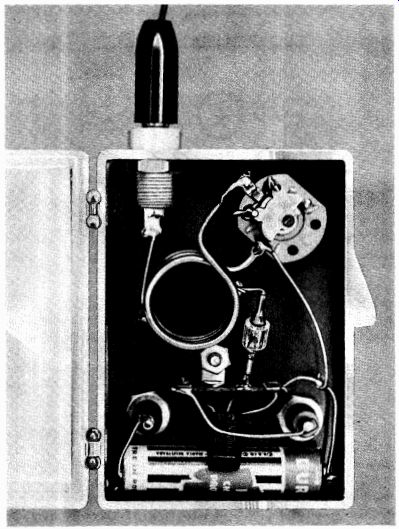
Fig. 155-Parts placement can be seen from inside photo of finished unit.
This receiver can be made in two versions. Addition of the second transistor (the NPN 2N35, TR2) will increase the volume. This is particularly important if you want to use this receiver in a noisy area or with a very high impedance earphone. If your earphone has a d.c. resistance of between 1,000 and 1,500 ohms, the simple circuit with the single transistor will probably work very well. A 2,000-ohm headset re quires the additional transistor and an increased battery voltage (3 volts).
After the receiver is completed, it can be tested by bringing coil L1 near a grid-dip oscillator tuned to the vicinity of 100 mhz. If an antenna is attached to the GDO and the GDO is modulated with a tone, it should be possible to receive the signal 10 or 15 feet away.
Don't expect the signals to blast your ears. The sensitivity is very low. A good check for sensitivity and operation is to listen in near a running automobile. If the sensitivity is what it should be, you should hear the popping and snapping of the car's ignition.
Using the model at the local airport, the control transmitter should be heard several hundred feet from the tower, and the approaching planes should be heard as they come in for a landing.
Two-tube Economy Amplifier
This is a simple, low-cost amplifier that can be used with a crystal pickup or FM tuner. Although the circuit contains only two tubes, there is ample output for both of these applications. Utilizing dual purpose tubes (a 6SL7 for two amplifying stages and a 117N7 as a rectifier and beam output tube) its performance is equal to that of a three- or four-tube unit.
A tapped tone control boosts either the bass or the treble ranges and can be used to equalize older recordings. Fidelity-wise, there are three applications of inverse feedback to make it nearly distortion free.
But naturally, the 117N7 tube with its 1-watt output cannot be expected to rival a 40-watt "monster." In place of a "hot" chassis, which is found in most small amplifiers of the a.c./d.c. variety, all circuit grounds terminate at a single lug which is chassis-grounded through capacitor C2.
Voltage for the two tube filaments is obtained from two different sources. The 117N7 tube (V2) works right across the 117-volt a.c. line without a dropping resistor. A 290-ohm resistor line cord is used to obtain the necessary voltage for the 6SL7 (V1).
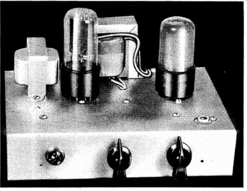
Fig. 156-Two-tube power amplifier. Pilot light, tone control, and volume control
are on front panel.
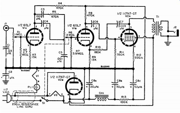
Fig. 157-Schematic of two-tube amplifier.
PARTS LIST
C1-0.03-lad., 300-volt paper tubular capacitor
C2, C4, C6-0.1-ittd., 300-volt capacitor
C3, C5-0.001-10d., 200-volt paper tubular capacitor
C7-0.003-tad., 220-volt paper tubular capacitor
C8a/C8b/C8c-20-30-50-ufd., 150-volt d.c. electrolytic capacitor
CH1-450-ohm, 50-ma. filter choke (see text) PL1-6.8-volt pilot light (screw base) and socket 11-Phono jack with insulating washer J2-Microphone type jack RI-1-megohm audio taper potentiometer (Mallory Midgetrol 1-meg. Taper 1) R2-2.7-megohm, 1/2-watt resistor R3, R9-13,000-ohm, 1-watt resistor R4, R5, R8-470,000-ohm, 1-watt resistor R6-2-megohm potentiometer, tapped at 500,000 ohms, with switch (1 RC 2-meg. 13-139X)
R7-3.9-megohm, 1/2-watt resistor
R10-180,000-ohm, 1-watt resistor
R1 1-390,000-ohm, 1/2-watt resistor
R12-220-ohm, 1/2-watt resistor
R13-100,000-ohm, 1/2-watt resistor
S1-S.p.s.t. switch (on R6)
T1-Universal output transformer (Stancor A-3856 or equivalent)
V1-651.7-GT tube
V2-117 N7-GT tube 1-5" x 7" chassis (minimum) 1-290-ohm resistor line cord
Misc. tube sockets, wire, hardware, knobs
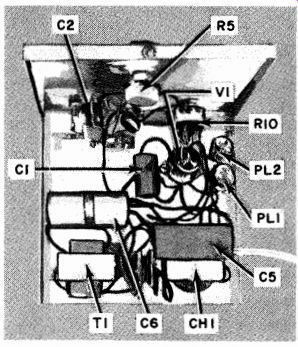
Fig. 158-Underside of amplifier chassis showing terminal board and point-to-point
wiring. Note that the major components are crowded to the back of the chassis
to keep hum away from the tone and volume controls.
The pilot light (PL1) is connected in series with the 6SL7 heater.
Although a choke (CH1) is shown in the wiring diagram, the constructor may substitute a 450-ohm resistor (5 watts) if he wishes.
All leads should be as close to the chassis as possible. Because of the nature of the resistor line cord, the "on-off" switch (S1) is connected in the ground lead. The cord dissipates heat when working normally. Don't be alarmed if it becomes quite hot to the touch.
Wire carefully and avoid large blobs of solder. In the case of the ground lug, use a two- or three-lug terminal strip and connect the lugs together with a heavy piece of bare, copper wire. Avoid letting solder run down to touch the chassis--this could result in a direct short. Re member that when the line plug is inserted and the switch is "off," the ground side of the circuit will be safe to touch, but anything connected to the other side of the line definitely will not be safe! The output transformer is a high-quality universal-type transformer such as the Stancor A-3856. Follow the manufacturer's instruction sheet in matching your speaker impedance to the 3,000-ohm load resistance of the 117N7. For increased high-frequency response, try the A-3850, a unit of slightly larger size.
When you first turn the amplifier on, a bright flash of light will be seen in the 117N7 tube, which will then heat up rapidly. The pilot light (if connected in series) should be operating near its maximum rating.
With nothing connected to the input and the volume control in its loudest position, hum should be inaudible. (There will be a slight hum if you substitute a resistor for the filter choke.) If any hum is heard, reverse the line plug.
Connecting a record changer or tuner may produce some hum. If it does, reverse both plugs several times until an ideal match is indicated by an absence of hum.
For best operation, the constructor should adhere closely to all specified circuit values-with several exceptions. One exception is R13, which is in the power-supply circuit. If for some reason you would like more gain, this resistor can be brought down to 50,000 ohms to supply more plate voltage to the 6SL7.
Other components open to change are R10 and C7, which form the feedback loop. The over-all gain of the amplifier can be adjusted at this point. Decreasing the value of R10 decreases the gain, and vice versa. C7 controls the amount of feedback at lower frequencies. The larger the value, the more bass is fed back to the cathode, which results in decreased bass response. If you have a highly efficient speaker enclosure, you may want to use a larger capacitor and decrease the amount of bass, C7 can be varied up to 0.01 microfarad.
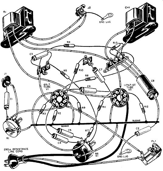
Fig. 159-Wiring of amplifier.
Transistorized Intercom
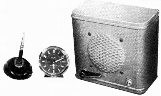
Fig. 160-Transistorized intercom.
The home intercom system is a "natural" for "transistorization." By powering it from a 6-volt battery, the possibility of shock or power-supply hum can be eliminated. This unit is designed around three CK722 transistors and a type 2N255 power transistor. The circuit is simple, and you should have little difficulty in assembly.
The chassis can be constructed of a scrap piece of perforated Masonite, 1/4-inch plywood (with holes drilled for parts mounting) or even sections of an old cigar box. It is a good idea to apply a couple of coats of acrylic spray to the "chassis" before mounting the components. This will prevent moisture from wilting it after installation in the cabinet.
The power transistor is mounted with 6-32 nuts and bolts, as are T1, T2, and T3. Place a soldering lug under one of the 2N255 mounting nuts and use it for the collector connections. (The 2N255 has the collector internally connected to its shell, therefore, the shell cannot be grounded.) Insert tie points wherever convenient and run the common leads to them. The rear bracket and the brackets mounting the switch and control can be cut from an aluminum angle or shaped from sections of a "tin" can.
PARTS LIST
B1-6-volt battery
C1, C3-2-p,fd., 6-volt electrolytic capacitor
C2, C4-10-ufd., 6-volt electrolytic capacitor
C5-30-p,fd., 6-volt electrolytic capacitor
C6-1001..ifd., 6-volt electrolytic capacitor
R1, R9-100-ohm, 1/2-watt carbon resistor
R2-330,000-ohm, 1/2-watt carbon resistor
R3-3000-ohm potentiometer (Gain Control)
R4, R7-4700-ohm, 1/2-watt carbon resistor
R5-270,000-ohm, 1/2-watt carbon resistor
R6-47-ohm, 1/2-watt carbon resistor
R8-100,000-ohm, 1/2-watt carbon resistor
R10-4700-ohm, 1-watt carbon resistor (see text)
S1-S.p.s.t. toggle switch (Power)
S2-D.p.d.t. spring return rotary switch (Centrelab No. 1464)
S3-S.p.d.t. normally open push-button switch (Mallory 2003-L)-in Remote
T1-Input transformer; 3-ohm primary, 4000-ohm secondary (Argonne No. AR-125)
T2-Driver transformer; 500-ohm primary, 8-ohm secondary (Argonne No. AR-125)
T3-Output transformer; 48-ohm primary, 3.2-ohm secondary (Argonne No. AR-503)
TR1, TR2, TR3-CK722 transistor (Raytheon)
TR4-2N255 transistor (CBS Hytron)
SPKR.--4" PM speaker, 3-4 ohm voice coil
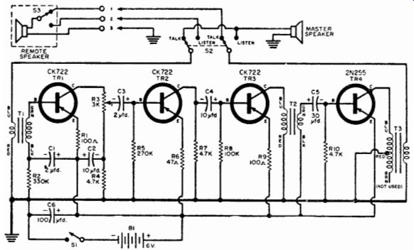
Fig. 161-Intercom circuit uses three CK722 transistors and one 2N255 power
transistors.
Layout and wiring are not especially critical as long as care is taken to keep input and output circuits well separated, preferably at opposite ends of the chassis. If your intercom shows a tendency to whistle, squeal, or howl, the problem is probably due to audio coupling through the power supply or to bad parts layout.
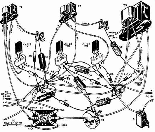
Fig. 162--Pictorial of parts mounting of transistor for final assembly.
The base resistor (R10) of the output stage is of a higher than normal value in order to minimize battery drain. If the circuit shows a tendency to distort or overload on strong signals, the value of R10 can be reduced. With the original 47,000-ohm value, the battery drain will be approximately 50 milliamperes. Lowering the value of R10 will increase the amount of current drawn. As far as the input and output connectors are concerned, any convenient three-terminal strip will do.
Binding head connectors were used in the model, but other types may be more easily available.
The 6-volt battery can be made up of 1 1/2 volt "D" flashlight cells mounted in series-wired battery clips. If more convenient, a single 6-volt portable-radio type "A" battery can be used.
Operation of the master unit can be achieved with any standard PM speaker as a remote. Standard three-wire intercom cable should be used for interconnection of the master and remote. The remote speaker will transmit only when its push-to-talk switch is depressed. This feature can be disabled by connecting a jumper wire between output terminals 1 and 2.
After installation, the gain control, which is mounted at the rear of the chassis, should be preset to a standard operating level and should not need readjustment until the batteries age.
The little job's independence of the a.c. power line makes it an ideal companion in areas where power is either not available or unreliable.
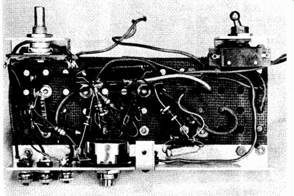
Fig. 163-Amplifier chassis shown from below with major parts installed.
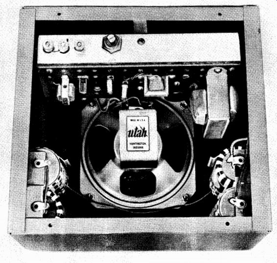
Fig. 164-Completed intercom mounted in cabinet.
Transistorized Photoflash
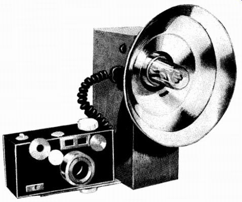
Fig. 165-Electronic photoflash uses transistor oscillator to supply high voltage
for flashbulb.
The electronic photoflash outfit described here is a good and comparatively inexpensive compromise.
It operates from either house current or from four inexpensive size D flashlight cells, so battery cost is trifling. It is a single unit that is easy to build and is rugged and dependable in operation. The photoflash tube is mounted in neoprene under a glass dome to protect it from injury.
In order to design in all of these features, it was necessary to accept more size and weight than is considered ideal--2 3/4 inches by 4 1/2 inches by 7 3/4 inches, and 4 1/2 pounds with batteries. The housing can be constructed of .063-inch aluminum sheet with heavier gage (.125-inch) in the base plate to which the mounting bracket is attached. It is assembled by using sell-tapping sheet-metal screws to hold aluminum rods or angles as cleats.
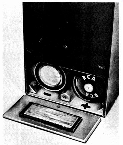
Fig. 166--Battery compartment with batteries installed.
Components are mounted on each of the side panels and prewired before the cabinet is assembled. Power transformer, transistors (mounted externally) and resistors of the oscillator, and the battery terminals are on the back panel. The batteries are a snug fit between the back panel and the main storage capacitor.
A removable section in the bottom of the case provides access to the batteries. The lower battery contact, an aluminum strip, is glued to a strip of plastic to insulate it from the case. This plastic strip is glued to the inside surface of the battery access door plate.
The transistors must be mounted on 1/16-inch composition with the mounting screws insulated from the case with composition shoulder washers. A thick plastic should be used between transistors and case because, with the use of thinner material, an electrostatic voltage may develop in the case.
No part of the circuit is electrically connected to the case because most camera flash synchronization contacts have one side grounded to the camera body. By keeping the case isolated, there is no need for a polarized flash cord connection.
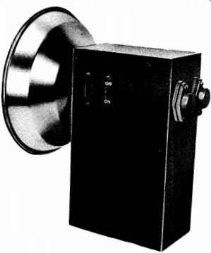
Fig. 167-Left-panel view showing power switch and recessed 117-volt socket.
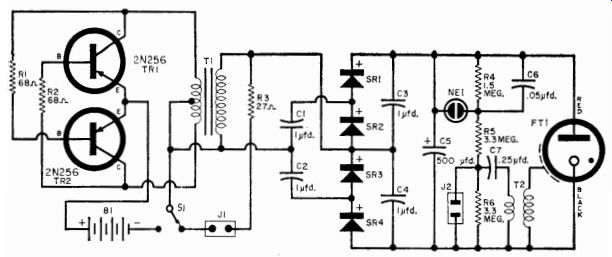
Fig. 168-Schematic of transistorized photoflash
PARTS LIST
B1-Four 1.5-volt standard size "D" dry cells
C1, C2, C3-1.0-ufd., 400-volt tubular capacitor
C5-500-ufd., 450-volt electrolytic capacitor (Sangamo DCM or equivalent)
C6-0.05-ufd., 200-volt tubular capacitor
C7-0.25-ufd., 400-volt tubular capacitor
FT1-Flash tube and reflector combination (Amglo HD-2AR; available from Amglo Corp., 2037 W. Division St., Chicago, Ill.)
J1-TV-type a.c. input receptacle
J2-Rectangular a.c. outlet (for camera sync connection)
NE1-NE-51 neon lamp
R1, R2-68-ohm, 1-watt resistor
R3-27-ohm, 1-watt resistor
R4-1.5-megoh m, 1/2-watt resistor
R5, R6-3.3-megohm, 1/2-watt resistor
S1-S.p.d.t. slide switch
SR1, SR2, SR3, SR4-Silicon rectifier (Sarkes Tarzian M150)
T1-Modified 6.3-volt filament transformer (Stancor P6134-see text)
T2-Ignition coil (Amglo ST-25)
TR1, TR2-2N256 power transistor (CBS)
The left panel of the case has the s.p.d.t. switch (S1) and a recessed TV-type a.c. connection (J1) mounted on it. An ordinary TV cheater cord is used when the flash is operated on house current, and the switch is wired so that the a.c. input is in the circuit only when the batteries are off.
Fig. 169-Interior view of flash unit with front panel removed.
Note the rods which hold the cells in place.
On the right-hand panel is an ordinary a.c. outlet (J2) into which the flash cord from the camera is plugged, the neon charge-indicating lamp (NE1) is mounted in a 5/8-inch rubber grommet and connected to a 4-point tie strip. Tape the tiny trigger transformer (T2) to the tie strip. All of the components shown in the schematic between the storage capacitor (C5) and the flash tube (FT1) can be mounted on this panel and wired before it is attached to the case.
The flash tube and its reflector are mounted on the front panel, using the two bolts provided. Note that the red lead goes to the positive terminal of C5, the black lead to negative, and the white lead to T2.
This leaves only the four silicon rectifiers and the four capacitors (C1, C2, C3, and C4) of the voltage quadrupler. They also are prewired using a physical layout which corresponds to the placement shown in the schematic. Considerable space is saved by using pigtails on the rectifiers instead of mounting clips.
The quadrupler is wrapped in plastic and the unit placed against the front panel when the case is assembled. It is held in place with the storage capacitor which is kept in position with two shaped aluminum rods fastened to the side panels.
Assemble the front, rear, and right side panels of the case, put the voltage quadrupler and storage capacitor in position, and complete most of the interconnecting wiring. Fasten the left panel in place and wire the switch and a.c. input from above. The top and bottom of the case are then fastened in place to complete the assembly.
Use a 1/4-inch tapped hole in the heavy bottom plate to attach the camera mounting bracket. Hold the battery access panel in place with one screw. Mark the battery polarity on the side of the opening to reduce the possibility of inserting the batteries incorrectly. If desired, the battery trap door can be hinged. The plate that is mounted on the door and which contacts the positive and negative terminals of the batteries must be insulated from the door itself. It may be glued to a piece of plastic which, in turn, is glued to the door panel.
Fig. 170-Voltage quadrupler subassembly as it is wired immediately before
being insulated.
The only component which requires modification is the power-supply transformer (T1). Take apart its frame and laminations and remove the entire center-tapped 6.3-volt winding. Using only 20 feet of this wire, rewind the secondary, taking off a tap at its mid-point, and reassemble it. This rather simple operation is necessary to provide sufficient voltage for satisfactory operations as the battery output drops with use.
The layout shown is not offered as the final answer. The unit could probably be made smaller and with a different shape. Some builders may like a two-unit flash outfit with the power and storage components carried in an over-the-shoulder case and the rest of the components mounted with the flash tube and reflector on the camera. Amglo offers a back cover for the reflector for such an installation.
That's all there is to it!