AMAZON multi-meters discounts AMAZON oscilloscope discounts
LEARNING OBJECTIVES:
Upon completion of this section on the planning and designing of electronic equipment, the student should be able to:
1. Understand the electrical criteria involved in packaging the electronic system.
2. Select the appropriate type of chassis.
3. Place components and hardware in their optimum positions in a package.
4. Incorporate maintainability in package design.
5. Incorporate human engineering in package design.
0. INTRODUCTION
A high-quality piece of electronic equipment can result only from thorough, careful planning and application of the fundamental mechanical and electronic design factors. Of these factors, reliability is one of the most important. A highly reliable piece of equipment will result if all the design factors that govern packaging are considered during the preliminary planning stages.
In this section we examine the numerous, common packaging problems involved in the preliminary planning stage of constructing electronic equipment. Consideration is given to space and weight requirements, component and hardware selection, chassis materials and configurations, component and hard ware positioning, maintenance, and human engineering. Specific problems are related to the packaging of a stereo amplifier that serves as an example packaging problem throughout this text. Each step of the packaging phase is applied, in sequence, to this amplifier, which illustrates most of the common packaging problems.
1. SPACE AND WEIGHT REQUIREMENTS
Once the need for a system has been determined, the mechanical and electronic design engineers will stipulate the many specifications for the completed unit in order to ensure that it will be compatible with its predicted environment. For example, packaging for vehicular installation often introduces complex dimensional and weight restrictions. If space is at a premium and size and weight must be kept to a minimum, the system must be packaged in subassemblies or adapted to a modular design that will fit into the various-shaped spaces that are characteristic of vehicles such as ships and air or space craft. Stationary equipment, such as that used in homes and laboratories, is normally subject to fewer severe environmental constraints and is designed around chassis, cabinets, racks, panels, and consoles that are commercially available. Modern stationary equipment makes extensive use of single- and double-sided printed circuit boards ( FIG. 1).
2. COMPONENT AND HARDWARE SELECTION
Once the component values of the system have been designed, the circuits are tested in experimental or breadboard form. It is generally the responsibility of the design engineer to determine the final selection of component values and ratings. Technicians must also be acquainted with the factors that govern these selections in order to enable them to choose the best available component for the specific applications. The final choice of components and hardware will be somewhat dependent on cost and availability, but the prime concern should be reliability. Size, shape, and the finished appearance of the unit also dictate part selection.
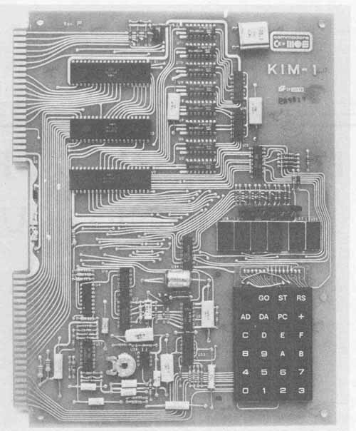
FIG. 1 Microprocessor trainer.
All electronic equipment should be as compact as possible, without reaching the point at which extreme component density prohibits assembly and ser vice. Very often, the size of the unit is predetermined by its application, and the technician is compelled to work within established limits. The variation in size and mounting characteristics among commonly available components of the same electrical ratings makes it possible to satisfy even extreme dimensional restrictions.
The first criterion used in selecting components is, of course, that they meet the circuit’s electrical demands with high reliability. Manufacturers’ rated tolerance must be within design values. The closer the tolerance to the rated value of the component, the more it costs. Since cost is always a consideration, a technician should never choose components with closer tolerances than are necessary for the particular application. For example, if a resistor value is designed for 220 ohms with 10% tolerance, it certainly would be uneconomical to select a 1% resistor, since it may not appreciably improve circuit performance or reliability.
Voltage, current, power levels, frequency, and continuous or intermittent operation are the major circuit parameters that govern the selection of both the component value and type. In prototype construction the maximum electrical ratings s levels) of the components must be derated to ensure reliability. Derating provides a sizable safety factor so that components operate well within their limits. In general, resistors are operated about 50% below their power stress levels. As an example, if a circuit resistor is required to dissipate 1/4-watt, the resistor actually chosen would have a 1/2-watt rating. On the other hand, a limit must be placed on over-derating or compactness will be compromised. Using a 2-watt resistor where a 1/2-watt resistor will operate within derating values or an electrolytic capacitor with a working voltage of 100 volts where 10 volts would be more than adequate would sacrifice size, weight, and expense without improving circuit performance.
Environmental factors and human engineering also come into play in the determination of which component or style of hardware to use. To illustrate this, hermetically sealed components would be necessary for protection against extremely humid conditions. From the standpoint of safety, external accessibility, and appearance, an extractor post fuse holder would be selected over a fuse block ( FIG. 2).
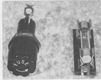
FIG. 2 Extractor post fuse holder and fuse block.
It is important that the technician realize and appreciate that in many cases, component and hardware selection is one of compromise. This compromise comes about through the combination of availability, cost, size, and tolerance. Regardless of the choice of components, in the final analysis the system must function within the established operating specifications. Otherwise, it is of little value, even though it may be well packaged.
Hardware items are sometimes a matter of personal choice. However, the size of such items must be realistic and fit the general scheme of the system. Miniature and subminiature hardware should not be selected when high component density is not required. In many instances, the selection of hardware such as switches, indicator lamps, connectors, jacks, and plugs is determined by those styles and types that are conventionally used in similar applications. If the unit being designed is to be used in conjunction with other units in an existing system, much of the hardware would be selected on the basis of mechanical and electrical compatibility and similar physical appearance. As an example, an existing system whose interconnections are terminated in Cannon connectors would require a special cable if a newly designed addition to the system used Jones-type connectors. Again, if a system makes use of pc (printed circuit) board connectors, additional boards used in the same system must be of a similar type (Fig. 3).
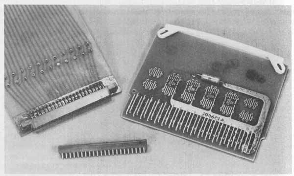
Fig. 3 Typical PCB connectors.
With the ever-widening use of integrated circuits, packaging has become more complex and a heavy reliance on printed circuitry has resulted. Printed circuits provide the only realistic solution to the problems associated with mounting transistors and the intricate wiring that is characteristic of integrated circuits. In the preliminary planning stage of construction, the technician is faced with the problem of using partial or total printed circuitry in a design. The solution to this problem often dictates the selection of the most suitable component and hardware types and styles. Although complex, printed circuits have reduced many packaging problems involving size, weight, and production uniformity. Since such a large percentage of components are de signed for use with printed circuit boards, the technician will encounter little problem in finding components available.
Some circuits require variable ,components, which are used only for initial adjustments for optimum circuit performance. Once these adjustments are made, ready access to the component is not necessary. These components are normally chassis-mounted or adapted to printed circuit design, as shown in FIG. 4.
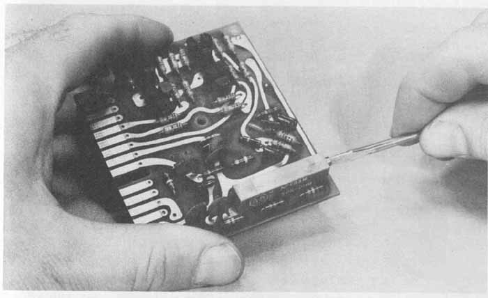
FIG. 4 Screw-adjustable potentiometer for printed circuit applications.
3. CHASSIS MATERIALS AND CONFIGURATIONS
Sound mechanical design is an essential element of electronic equipment pack aging. Components must be provided with a sturdy mounting base that will hold them in a fixed position so that they may be electrically connected. The metal frame on which the components are normally mounted is called the chassis. The overall dimensions of the chassis are determined by the final component layout of the circuit. The chassis configuration is selected through an evaluation of the following factors: circuit function, size, area restrictions, rigidity, component accessibility, and available manufacturing and fabricating facilities.
The two basic types of chassis are the box and the flat plate configurations. Other chassis shapes are variations of these. FIG. 5 illustrates several common commercially available chassis that are widely used in industrial and consumer product applications.
Factors that determine the style of chassis to use in a particular application are: weight of the heaviest components; use of controls and indicators such as switches, potentiometers, meters, and lamps; circuit and operator protection; portability; and appearance. If heavy are to be mounted, a simple U-shaped as shown in FIG. 5a, may not provide enough strength, especially if aluminum is the chassis material. A more sturdy design, such as the box chassis in FIG. 5b, should be considered. Here, tabs on the long sides of the chassis are folded behind the short sides and allow for the corners to be mechanically secured by sheet metal screws, rivets, or spot welds. Small self- contained circuits are packaged in chassis-enclosure combinations, as shown in FIG. 5c. Some circuit applications, particularly test equipment, require extensive use of meters, knobs, and indicator lamps and in addition must be portable. A reasonable selection for this application is the chassis and enclosure configurations shown in FIG. 5d or e, which provide a front panel for mounting controls and indicators, and, in some cases, handles for improved portability. FIG. 6 illustrates a typical portable package.
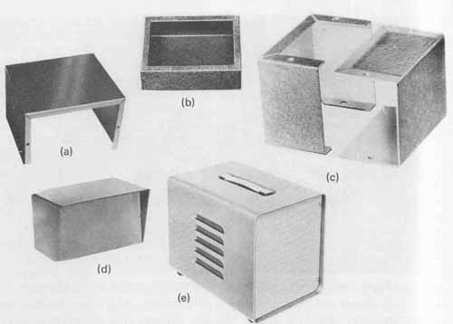
FIG. 5 Commercial chassis configurations; (a) U-shaped; (b) standard
box; (c) small utility box; (d) front panel and enclosure; (e) portable
equipment case. Courtesy of Bud Radio, Inc., Willoughby, Ohio.
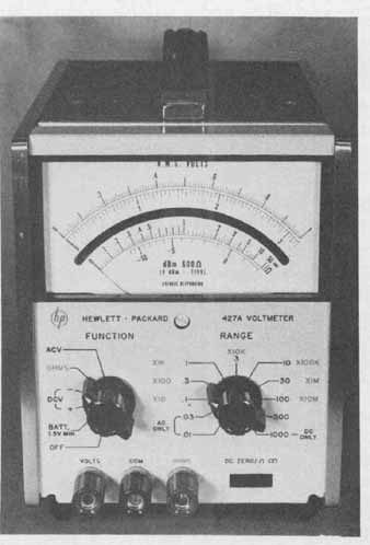
FIG. 6 Handles improve portability of test equipment.
Chassis are generally fabricated from sheet metal but may also be cast. The most common types of materials used for chassis fabrication are aluminum, aluminum alloys, low-carbon cold- or hot-rolled steel and molded plastics. Special applications may call for chassis constructed of copper, brass, or magnesium. The choice of materials for chassis depends on strength, weight, environmental conditions, finish, electrical and thermal requirements, cost, and special circuit demands -such as shielding. Aluminum chassis are the most readily available commercially in a variety of height, width, and depth dimensions with gauges (metal thicknesses) ranging from Nos. 14 to 20 in a wide selection of alloys and tempers (metal hardness). (See Appendix I for a table of metal gauges and their decimal equivalent thicknesses for aluminum and steel.) Aluminum used in chassis construction is light, strong, easy to work, and relatively inexpensive. It also requires no protective finish, since it does not normally corrode. Steel chassis need to be finished with a protective coating to prevent corrosion and to improve the appearance. (Additional information on chassis finishing is given in Section 9.) Although steel chassis are more difficult to work with than aluminum and require additional care and finishing, they are more rugged than a comparable gauge in aluminum.
If circuit design characteristics include frequencies such as VHF [ high frequencies—30 MHz (megahertz) to 300 MHz] and UHF (ultrahigh frequencies—300 to 3000 MHz), copper or copper-plated chassis are used because their conductivity is higher than that of aluminum or steel. This characteristic is especially desirable if the chassis is used as part of the electrical circuit.
Once the chassis configuration and material have been determined, the next step is to establish the size of the finished chassis. Factors that determine the size are the number and the dimensions of the components and the component density and positioning.
4. COMPONENT AND HARDWARE PLACEMENT
The packaging of an electronic system involves the positioning of parts and components to determine their optimum density and location, finished chassis size, and a balanced layout. Both electrical and mechanical factors are taken into consideration when packaging. Logical sequence dictates that mechanical criteria are applied first.
Large, heavy components such as transformers and filter chokes should be placed near the corners or edges of the chassis, where the greatest support exists. If several heavy components are being used, they should be evenly distributed over the entire chassis. Power transformers are normally positioned to the rear of the chassis to avoid the ac line cord running near or through critical circuit areas. Fuses, cable connectors, and infrequently used binding posts and jacks for extern antennas, or remote speaker connections also should be positioned to the rear ( FIG. 7a). Control knobs, switches, frequently used binding posts or jacks, meters, dials, and indicator lamps are generally located to the front of the chassis ( FIG. 7b). These items are not mounted directly to the chassis but to a front panel or cabinet. Electrical connections between the panel-mounted and chassis-mounted components are then made directly or to intermediate terminal points. Panel-mounted hardware and components should be positioned to provide balance in their appearance and to ensure ease of operation, unobstructed visibility, and a neat and orderly wired package.
Whenever possible, speakers should be front-positioned so that the sound is directed toward the operator. At times, however, then tone quality is important, a larger speaker is required and it may be necessary, because of physical size, to position it elsewhere. Sacrificing position for tone quality is not an uncommon practice.
Electrical criteria often impose restrictions on component placement. Common circuit problems that must be considered in packaging to ensure proper circuit performance are thermal radiation from components such as resistors and power transistors AC hum introduced into an audio circuit and distributed lead capacitance and inductance, which can drastically affect audio circuits and RF (radio-frequency) circuits. These circuit problems are discussed in the following paragraphs.
FIG. 7 External hardware and component placement: (a) typical rear-mounted
hardware; (b) typical front-mounted components and hardware.
Low-power transistors and integrated circuits are heat-sensitive devices and must be positioned a reasonable distance from any component that generates considerable heat. One component that gives off a large amount of heat is the power transistor because it is designed to operate at near-maximum ratings. In most applications, normal air convection does not provide for adequate heat dissipation and heat sinks are necessary. Heat sinks are metal configurations that, when brought into physical contact with the transistor case, absorb and dissipate a large portion of the generated heat. The chassis itself can be used as a heat sink, but power transistors are manufactured with the collector electrically connected to the case. If this creates an electrical problem when mounted directly to the chassis, a mica washer is used. This mica washer electrically insulates the case from the chassis without causing severe adverse effects to the thermal conductivity between the case and the chassis. This mounting arrangement is shown in FIG. 8. Silicon grease is also used on both sides of the mica washer to increase thermal conductivity. If chassis sinking alone would not provide adequate heat dissipation, fin-type sinks like those shown in FIG. 9a are employed. If low-power devices require heat sinking, the type shown in FIG. .9b, which is not chassis-mounted, is often used. The proper size and configuration of sink required is predetermined during the circuit de sign stage. The problem of providing adequate space for the sink is left to the technician.
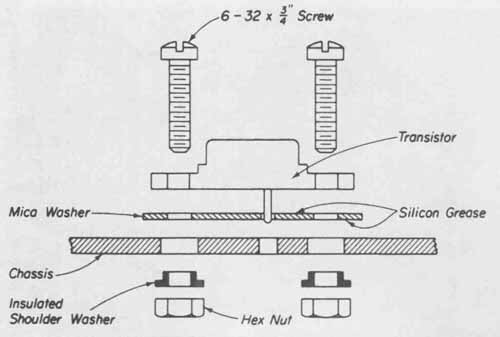
FIG. 8 Correct mounting arrangement of a power transistor to a metal
chassis.
What is commonly referred to as ac hum or 80-hertz hum, is a condition common to most electronic circuits employing power transformers. A 60-hertz signal, usually originating at the power transformer, can be induced into the input stages of the circuit. This induced signal is then amplified along with the desired signal, resulting in a steady hum. Shielding the signal lead or, by proper placement, making the input lead very short, will minimize this problem. It is advisable, however, to make it a common practice to locate power transformers, ac leads, or any source of electromagnetic radiation away from the signal input leads.
If circuitry employing RF frequencies is to be packaged, special attention must be given to the lead lengths required by the component and hardware positions. Because of the lead capacitance and inductance, which become a problem at these higher frequencies wires used for electrical connections must be kept as short as possible. This is especially true at the input stages, as in the case of a receiver’s local oscillator section, wherein the leads are extremely susceptible to noise pickup. FIG. 10 shows an example of a compact RF package with the components positioned so as to keep the leads as short as possible.
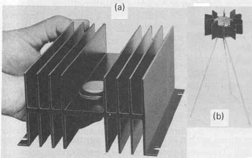
FIG. 9 Typical heat-sink configurations: (a) Chassis-mountable heat
sink for medium- and large-power devices; (b) heat-sink style for low-
power devices. Courtesy of Thermalloy, International Electronic Research
Corporation and Wakefield Engineering Company, Inc.
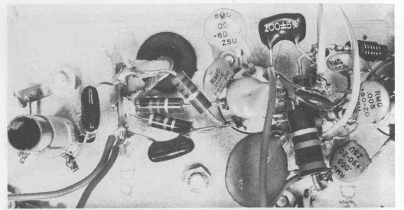
FIG. 10 Typical RF package design.
If antenna positioning is involved in the circuit layout, it is important to locate the antenna input as close to the input circuit as possible to avoid stray pickup. In addition, if the antenna is designed to be totally contained within the unit, it should be surface and kept as far away from metal elements as possible. This avoids the problem of picking up undesired frequencies. Component and hardware placement is by far the most involved and time-consuming phase of planning a package. Performance and reliability of the system will depend heavily upon this phase of design.
5. MAINTENANCE
Maintainability is a measure of the ease, accuracy, and time required to restore a circuit or system to its normal mode of operation once a failure or abnormal function is detected. Maintenance covers two general procedures. First is the repair of failures and defects. Second is preventive maintenance, which deals with normal or routine checks and servicing of equipment. The object of preventive maintenance is to keep equipment operating trouble-free and at optimum performance. Certain precautions should be taken in the design of any package to minimize unnecessary maintenance. Whenever leads must pass through a hole in a metal chassis or bend around the edge of a bracket, either a grommet or clamp should be used to prevent abrasion of the lead insulation, which would cause a short circuit.
High ambient temperatures within enclosures can eventually cause components to overheat and fail. To ensure cool, trouble-free operation, approximately 6 cubic inches of space per watt of power to be dissipated is necessary if normal air convection is to be relied upon for cooling a unit. Vents or holes must be provided, preferably at the top of the enclosure surrounding the circuit. If units are stacked in a rack, those units that dissipate the most heat should be located in the uppermost position to prevent the heating of components in other units. Whenever possible, avoid liquid coolers and blowers. Liquid cooling systems are subject to failure, and blowers could cause air circulation that will cool certain components but overheat others. Air filters are often required when blowers are used, thus adding another maintenance dimension to the unit. Liquid cooling and blowers also add bulk and weight to the unit.
Enclosures, in addition to allowing circuits to function without overheating, must also be tight enough to isolate the components and wiring from dust or other contaminants that could accumulate in the circuit and cause failures. If large holes have to be formed in an enclosure for speakers, the entry of dust can be minimized by using a speaker cloth. For additional protection of the speaker cone, a grid or wire screen can be used with the cloth.
Well-designed enclosures minimize maintenance problems through the various types of circuit protection they afford. They can, however, present problems in terms of accessibility. Ease in maintenance is directly related to component accessibility. By locating access plates, doors, and openings near those components that are most subject to maintenance needs, repair and ser vice can be achieved easily, quickly, and accurately. Safety precautions should be built into the design when providing access to electronic circuits. Safety devices may have to be incorporated with the removable elements to avoid the possibility of electrical shock when working on the circuit through any access opening. ( FIG. 11). Providing for maintenance in packaging design is a compromise involving three factors: sufficient environmental protection, accessibility, and safety.
FIG. 11 Power cord attachment design necessitates its removal for safety
before servicing.
6. HUMAN ENGINEERING
In electronic packaging design, human limitations associated with the use of electronic equipment must be considered. These human limitations involve such things as vision, arm reach, and hand manipulation, which must be considered in order to select the most suitable controls and visual displays. The ease and accuracy with which the unit is operated depends on the proper selection and placement of these components.
Meters should not be so small as to make the reading of major and minor scales difficult. The type of scale used should fit the function of the unit. For example, if only circuit conditions are to be monitored rather than the finite values of electrical parameters, the use of smaller meters having fewer scale divisions is desirable. If, on the other hand, accurate measurements are required, a larger meter with numerous minor scale divisions is preferable.
Glare must be avoided when continuous dial and scale readings are necessary. If reflected light in the unit’s environment is excessive, glare shields such as the one shown in FIG. 5d, should be employed. In addition, the panel should be finished in a color possessing low reflective characteristics (see Section 9).
Control knobs and switches should be mounted within easy and comfort able reach of the operator and should not be crowded. If they are, accurate individual adjustments will be difficult to make and other settings may be disturbed. Keeping with accepted conventions in mounting panel elements is very important. For example, toggle switches that are to be operated in a vertical manner should be “on” when the lever is in the upward position. Potentiometer adjustments in a clockwise direction should cause an increase in the magnitude of the electric quantity. In rack- or console-mounted equipment, all visual displays and indicators, such as meters and indicating lamps, should be mounted as close as possible to the eye level of the operator.
Stali1it essential especially if the unit is portable and relatively light. Some controls, especially rotary switches, require substantial torque to actuate and may cause the unit to become unsteady while in use. This problem can be reduced or overcome by either mechanically securing the unit to a mounting surface or attaching rubber pads to the bottom corners. The pads not only provide greater friction but also offer protection to the working surface, in addition to serving as electrical insulators for the unit.
The consideration of human limitations and capabilities, then, must be of concern to the technician designing a package. Many manufacturers employ human engineering consultants to render advice about the placement of control elements. A unit may function properly, but it will not be acceptable if it is difficult to control, read, or adjust.
EXERCISES
A. Questions
1 List at least five design factors that go into the planning of a piece of electronic equipment.
2 Of those factors listed in Question 1.1, which do you consider the most important, and why?
3 What electrical criteria impose restrictions on component placement?
4 What are the two basic types of chassis from which all other variations are derived?
5 What is the purpose of a heat sink?
6 What is meant by human engineering in package design? Why is it important?
B. True or False
Circle T if the statement is true, or F if any part of the statement is false.
1 Stationary equipment design imposes fewer restrictions than does that for vehicular equipment. T F
2 A U-shaped chassis provides more strength than a box chassis. T F
3 Large and heavy components should be placed near the corners or edges of a chassis. T F
4 The most common material used to make chassis is copper. T F
5 In designing high-frequency circuits, the lead lengths should be as short as possible. T F
C. Multiple Choice
Circle the correct answer for each statement.
1 One of the most important design factors is (reliability, appearance).
2 In circuit design involving ultrahigh frequencies, the chassis should be made of (copper, plastic).
3 Transistors and integrated circuits (are, are not) affected by heat.
4 In the design of RF packages, the antenna must be positioned (close to, far from) the signal input circuit.