AMAZON multi-meters discounts AMAZON oscilloscope discounts
LEARNING OBJECTIVES:
Upon completion of this section on printed circuit board soldering, the student should be able to:
1. Understand the composition and temperature characteristics of soft solder.
2. Know the major classifications of fluxes and their applications.
3. Know the available soldering iron tip configurations and their temperature requirements for a variety of soldering applications.
4. Use a soldering iron to solder pc board connections.
5. Use a personal computer to obtain a thermal profile of a soldering iron.
6. Be familiar with common solder joint deficiencies, their causes, and methods to correct them.
7. Use de-soldering aids and tools.
8. Properly dip-solder pc boards.
9. Understand the wave-soldering process and the basic components of wave-soldering system.
10. Know how to obtain a thermal profile of a wave soldering process.
0. INTRODUCTION
With the components properly assembled, the final process necessary to complete the construction of the pc board is to produce sound electrical connections between the leads and the foil pattern. These connections can be produced by several methods, the most common of which are welding and soft soldering. Welding requires the use of complex and expensive equipment and, as such, rarely used in fabricating a prototype pc board. Soldering, on the other hand, can be performed quickly with less expensive equipment and results in excellent mechanical and electrical connections and protects the joint from oxidation. For these reasons, soldering will be discussed exclusively in this section.
Soldering is a metal solvent or chemical alloying action of the solder with the surfaces of the metal parts between which an electrical connection is formed. This completely metallic contact is produced by the application of soft solder with the heat of a soldering iron to the joint between the component lead and the terminal pad. The resulting connection is electrically sound, with the new alloy formed having different electrical and mechanical characteristics than either the solder or the metals joined. The soldering of pc boards requires the development of proper techniques if quality results are to be obtained. The three methods of soldering discussed in this section are (1) hand, (2) dip, and (3) wave soldering. These three methods are used extensively in pc board applications.
Specific information is also provided on the following topics: soft solder and its characteristics; the types of flux available and its application; the soldering iron, including the tip, power rating, and tinning processes; and hand- soldering techniques, with emphasis on the proper soldering of leads, swaged terminals, and conductor paths (tinning). Included is the technique of obtaining the thermal profile of a soldering iron with the use of a personal computer. A discussion of the characteristics of correct solder connections is presented to aid in visual inspection. De-soldering and the solvents used to remove the flux residues formed on soldered connections are also included. Finally, information on production-line methods of soldering, specifically clip and wave soldering, is presented together with a method of obtaining a thermal profile of the wave soldering process.
1. SOFT SOLDER AND ITS CHARACTERISTICS
Soft solder used extensively in electronic equipment construction is an alloy principally of tin and lead. Soft solder is differentiated from hard solder by its tin content and lower melting point. The amount of tin contained in soft solder ranges from 50 to 70%. The tin-lead ratio determines the strength, hardness, and melting point of the solder.
Solder liquefies at temperatures between 361 and 621°F (183 to 327°C), the exact temperature depending on the tin-lead ratio. A metal such as copper, which has a melting point of 1981°F (1083°C), can be successfully alloyed with solder at temperatures well below this value because of the solvent action of solder when it is liquefied. At the melting point of solder, a thin film of metal is dissolved from the copper surface, forming an alloy and establishing an electrically continuous joint. The formation of this alloy between the metal and the solder has its unique physical properties, such as torsional, shear, and tensile strength, which are different from those of either the solder or the metal. These properties will vary widely and will depend on the depth of alloying into the metal surface.
Pure tin melts at 450°F (232°C) (point B, FIG. 1) and the melting point of pure lead is 621° F (327 °C) (point A). When these two elements are combined, the melting point of the solder formed can be below that of either pure metal. A composition of 63% tin and 37% lead melts at 361°F (183°C), which represents the lowest melting point and most rapid transition from the solid to the liquid state of any other tin-lead ratio. This point, C, is also shown in FIG. 1. The 63/37 solder is termed the eutectic composition. All solder, with the exception of the eutectic composition, which melts sharply from solid to liquid, passes through a stage of softening between its solid and liquid stages known as the plastic range. A fusion diagram showing the temperature ranges for the various states of solder for all tin—lead combinations is shown in FIG. 1.
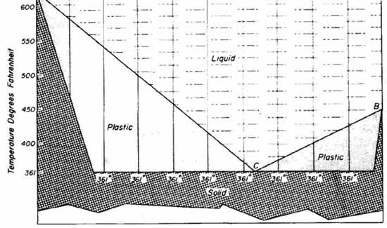
FIG. 1 Tin—lead fusion diagram. Courtesy of Kester Solder, Division
of Litton Systems, Inc.
In order to determine the proper tin—lead ratio for a specific application, the function of the connection must be examined. The necessary properties that will dictate the composition of solder are mechanical resistance to fractures due to stress, ability to form a continuous metallic connection at low temperatures, and cost. These factors are discussed here.
Since tin is more expensive than lead, solder with a higher tin content is more costly. It has been shown empirically that the highest joint resistance to stress exists with a 63/37 tin—lead ratio (eutectic solder). This concentration, therefore, affords the best alloying qualities in addition to the lowest melting point.
For most hand-wiring and printed circuit applications, solder with a tin- lead ratio of 60/40 is commonly used, because of its excellent wetting action. Wetting is the term used to describe the ability of the solder to readily spread and alloy uniformly over the entire metal surfaces to be joined. Eutectic solder is sometimes selected to take advantage of the lowest and sharpest melting- point characteristics wherein maximum precautions are necessary to avoid component heat damage and upsetting the joint as it cools. If these two considerations are not critical, 60/40 solder is an excellent compromise.
Solder for electronic applications is available in bars, sheets, wire spools, and special forms, such as pellets, rings, and washers. For hand-wiring purposes, solder wire ranges from 0.030 to 0.090 inch in diameter. The larger sizes are used for general-purpose work and the smaller for delicate soldering applications such as pc boards and solder pot-type pins (see Section 24) found on certain connectors.
Solder wire is also available with a core containing flux (see Sec. 2) in specific amounts to promote sound solder connections. For this reason, flux- core solder wire is used almost exclusively for electronic applications.
2. FLUX
The interaction of metal parts with the atmosphere forms a thin layer of oxide on their surfaces. This oxidation increases as the metal is heated and will severely interfere with the solvent action of solder, thus preventing alloying and the formation of an electrically continuous joint. Consequently, the oxide must be removed. Fluxes are used for this purpose. They are chemical agents that aid in soldering by removing thin films of oxide present on the metal surfaces to be soldered. When applied to the joint, the flux attacks the oxides and suspends them in solution, where they float to the surface during the soldering process. When the joint is heated, the presence of flux also prevents further oxidation in addition to lowering the surface tension of the metals, thereby increasing the wetting action. It is important to remember that flux is not a cleaning agent for removing grease or other contaminants. Its sole function is to remove the oxide film. For optimum soldering results, the parts must be thoroughly cleaned be fore the flux is applied.
The flux in no way becomes a part of the soldered connection but aids in the process. Upon completion of the soldered joint, a flux residue appears on its surface, which contains the captured oxides. This residue should be removed with an appropriate solvent.
The ability to rapidly remove oxide films from metal surfaces constitutes activity of the flux. It would appear that a highly active flux is ideally suited for electronic construction since it would afford rapid alloying and thereby reduce the possibility of heat damage to the components. This, however, is not the case. Highly active fluxes may be corrosive at room temperature and, if allowed to remain as a residue, will deteriorate the conductor surfaces or reduce the resistance of the insulation between soldered connections. Corrosive damage to components may also occur, since some of the active residues will gradually spread as they absorb moisture from the atmosphere. Even with suitable sol vents, there is no assurance of complete flux residue removal, especially around closely spaced terminals, connectors, or conductors on pc boards where complete solvent flushing is not possible.
There are three major classifications of flux: (1) chloride (inorganic salts), (2) organic (acids and bases), and (3) rosin fluxes. The chloride types are the most active (highly corrosive) fluxes. They absorb moisture from the atmosphere and strongly react with acid even at room temperature. Organic fluxes are slightly less active than the chlorides and are used mainly for confined areas in which fast soldering time is important and corrosion problems are not critical. Many of the organic fluxes are converted to an inert residue after thermal decomposition. They do not absorb moisture and are difficult to remove. For the reasons given above, chloride- and organic-type fluxes are not recommended for use in electronic construction. The rosin-type fluxes are used al most exclusively because of their non-corrosive characteristics at room temperature. They are corrosive at temperatures near the melting point of sol der. Consequently, they attack the oxide film during the heating cycle but are inactive when room temperature recurs. Rosin fluxes are available with activating agents that greatly improve their activity. These activated rosin fluxes are much more corrosive than pure rosin when heated and present the appearance of an instantaneous melting, wetting, and flowing action of the solder. They are essentially as noncorrosive at room temperature as the pure rosin types and are often preferable if a higher degree of flux activity is dictated such as in dip or wave soldering.
Liquid flux may be applied by wiping, dipping, spraying, or sponging. Wiping or dipping methods are not extensively used. Uniform flux coatings are difficult to realize when wiping with a brush and thorough wetting of all surfaces may not result when dipping because of air pockets or cavities created during this process. Another disadvantage of these two methods is that application of an excessive amount of flux requires extensive removal of residue after the soldering has been completed.
Spraying flux involves applying a fine mist to the joints. The use of this method ensures that leads and terminals are more uniformly and completely coated with flux. When spray methods of flux application are to be used, the manufacturer’s literature should be consulted regarding the recommended spray gun, nozzle, pressure, and solvent to use.
The application of flux with a sponge is perhaps the most effective and least messy method. To apply the flux, the board is firmly pressed against a sponge that has been saturated with liquid flux.
When hand soldering, the proper amount of flux can best be applied with the use of flux-core wire solder. This form of solder contains a core of solid rosin flux in a single or multiple core. There is no significant advantage in using multiple-core solder since it is essentially the volume ratio (amount of flux to solder) that determines optimum soldering conditions. Core sizes are available that provide a ratio of rosin flux per unit volume of solder of 0.6 to 4.4%. These ratios can be obtained for any size of wire solder. Indications are that 60/40 rosin flux core solder with a diameter of 0.040 inch and 3.6% flux is ideally suited for hand soldering pc boards and other electronic precision work.
3. THE SOLDERING IRON
The soldering iron, shown in FIG. 2, consists of four basic parts. These are the (1) tip, (2) heating element, (3) handle, and (4) power cord. Some soldering irons are equipped with either a cork finger grip or a heat deflector. These are designed to improve thermal insulation in the handle, which tends to become hot after prolonged use. In addition, the cork finger grip allows for more comfortable use of the iron.
When power is applied to the soldering iron, the tip is heated by direct thermal contact with the heating element into which it is set. The tip shown in FIG. 2 is an integral part of a porcelain-type heating element. The solder is liquefied when it comes in contact with a tip that has reached its operating temperature.
A soldering iron is selected for a specific application by considering the following factors: (1) size and style of the tip, (2) tip material, (3) required tip temperature, and (4) tip-temperature recovery time.
Selecting a tip style is somewhat a matter of personal preference. How ever, the shape of the particular tip used must provide the largest contact area to the specific connection for maximum heat transfer while minimizing the possibility of heat damage to surrounding leads or components. Some of the widely used tip styles are shown in FIG. 3. Each of the available tip configurations is designed for a specific soldering application. A brief description and application of each tip shown in FIG. 3 follows:
Chisel- and pyramid-style tips are commonly used for hand wiring and general repair work. The large flats of these tips allow large areas to be heated rapidly. The turned chisel and conical chisel tips lend themselves very well to soldering in confined areas, such as hand soldering components to double-sided pc boards.

FIG. 2 Soldering iron nomenclature. (from
free-ed.net)
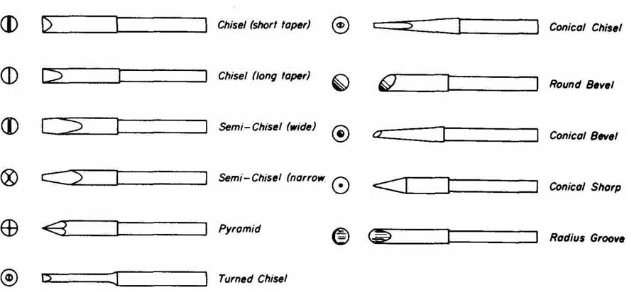
FIG. 3 Solder tip configurations. Chisel (short taper); Chisel (long
taper); Semi—Chisel (wide); Semi—Chisel (narrow); Pyramid; Turned Chisel;
Chisel (short taper); Chisel (long); Semi-Chisel (wide); Semi—Chisel
(narrow); Pyramid; Turned Chisel
Bevel designs are suitable for soldering terminal pad connections on single-sided pc boards if extreme conductor pad density does not exist. This style allows rapid heat transfer owing to the large tip surface area.
Conical tips are preferable for soldering high-density wiring, eyelets, and small heat-sensitive parts.
Radius groove tips also work well in high-density soldering applications and on round configurations such as pin connectors, pot-type terminals, and turret terminals.
Soldering iron tips are manufactured chiefly from copper and are avail able both in plated and unplated finishes. Typical platings for tips are iron, gold and silver. These platings protect the copper tip from corrosion and pit ting, which become pronounced over extensive periods of use. The plated tips should never be filed or cleaned with harsh abrasives that would remove the plating and expose the copper. The tips should instead be periodically cleaned by first dipping them cold into liquid rosin flux and then bringing them up to operating temperature to loosen any surface oxidation or contaminants (burned solder and flux residues) that may be present. Solder is then applied to the hot tip. Contaminated areas are easily detected by observing those areas that resist wetting by the solder. Sufficient solder has been applied when it begins to puddle. The tip is then wiped on a moist fine-pore cellulose sponge to remove the contaminants.
Tips should periodically be removed from the soldering iron because oxide will build up on the shank or threaded portion that fits into the heating element. If this oxide formation is not occasionally removed, the tip will seize in the element, making it difficult to remove and possibly damaging the element.
The required tip temperature is based on its application. For general- purpose soldering, such as to terminal strips and solder lugs, a tip temperature of 600 to 900°F (316 to 482°C) is sufficient. Printed circuit soldering requires fast heat transfer to the foil, yet excessive heat that could upset the foil bond must be avoided. For soldering to conductor patterns having widths of i-inch or larger and for terminal pads having -inch diameters or larger, irons with tip temperatures of 800 to 850°F (427 to 454°C) are recommended. When soldering to more delicate pc boards or extremely fine wire (28 gauge or smaller), tip temperatures of 550 to 700°F (288 to 371°C) are suggested. However, when fine-component wire is to be soldered, especially in the case of heat-sensitive devices, a tip temperature of at least 900°F (482° C) is recommended (if lead heat sinks are not used) so that rapid heat transfer occurs with a minimum amount of tip contact time.
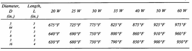
---TABLE 1
Comparison of Wattage Rating and Tip Temperatures for Various Sizes of Solder Tips
----
Manufacturers normally rate their irons in watts, typically available from 20 to 60 watts for electronic applications. It is difficult to compare exact tip temperature with wattage rating since the length and the diameter of the tip largely influence tip temperature. For example, a 25-watt iron with a 1 tip diameter and f-inch tip length will produce a temperature of approximately 680°F (360°C). Another 25-watt iron with a tip having the same diameter but a 1k-inch length will reach a temperature of approximately 605°F (3180 C). As a rule, tip temperature decreases linearly, approximately 10°F for every 0.10-inch increase in tip length. Tip temperature is inversely related to tip diameter. However, this relationship is not linear, as is the case of length versus temperature. Therefore, empirical data, such as that provided in TABLE 1, must be consulted. This table shows comparative values of tip temperatures to specific wattage ratings for three common tip diameters. The values given in this table are for iron-clad chisel-style tips having a length of inch.
A more general relationship of wattage to tip temperature given in TABLE 2. This table provides a comparison of the common wattage ratings to a range of tip temperature is that can be expected from any style or size tip. In general, approximately a 50°F change in tip temperature can be expected be tween the successive wattage ratings listed.
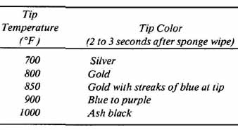
There is a useful technique for determining the approximate tip tempera ture of iron-clad tips by visual inspection. When the iron is heated to its idling (maximum operating) temperature, the flats of the tip are alternately wiped several times across the surface of a moist sponge. The color of the tip is ob served 2 to 3 seconds after wiping. There is a relationship between the color obtained and the approximate tip temperature. This relationship is given in TABLE 3. Tip temperature can be periodically monitored using this technique.
Recovery time is the rate at which a tip will return to its idling temperature after transferring heat (tip cooling) to the work during soldering. In mass production applications wherein a rapid succession of soldered connections are to be made, fast recovery time is absolutely essential. It is not of major concern in prototype work, however, since the recovery rate is normally much greater than the rate at which soldered connections are made.
---TABLE 2
Soldering Iron Wattage Rating versus Range of Tip Temperatures
Wattage rating | Range of Tip Temperatures
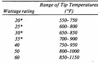
*Commonly selected wattage ratings for electronic applications.
----
---TABLE 3
Reference for Iron-Clad Tip Temperature by Visual Inspection
----
The following example will serve to illustrate how to evaluate the many available irons and tips to select the most appropriate one for a specific application. An iron will be selected for soldering a double-sided pc board having typical conductor widths of 1/32 inch with terminal pads of approximately 1/16 inch in diameter. Ideal tip temperature for pc board soldering is 800 to 850°F (427 to 454°C). As can be seen in Tables 1 and 2, a wattage rating of 35 watts will provide this necessary temperature with a 3/64 by 3/4-inch tip. The style of tip should permit ready access between components. A conical chisel design is selected since this configuration provides the desired contact area for component lead soldering to terminal pads. Finally, the iron-clad finish is chosen for durability. The tip selected for this example is quite versatile because of its thin chisel shape, which works well with both double- and single-sided boards.
In g the soldering iron that produces the best performance over an extended period of time is one that has high heat conductivity and low heat loss when in contact with connections to bring them up to soldering temperature. It should also have a cool, lightweight handle, a no-burn power cord with strain relief and a simple method for removing the tip and disassembling the iron to replace the heating element.
Where precise control of tip temperature is required, temperature-controlled soldering irons having tips with built-in temperature sensors are available. This type of iron is shown in FIG. 4. Temperature-controlled units allow for tip temperature settings from 500 to 800°F (260 to 427°C). They maintain the set idling temperature to within seconds after each soldering operation. This type of temperature control ensures consistent soldering temperature conditions.
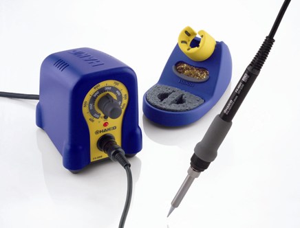
FIG. 4 Temperature-controlled soldering iron. (model FX-888 from Hakko)
4. THERMAL PROFILE OF A SOLDERING IRON
Modern personal computer technology has simplified the ability of obtaining an accurate thermal profile of a typical soldering iron. Analog Devices, Inc., has introduced a new family of signal-conditioning modules that can connect a type J thermocouple temperature sensor directly into the serial port of a personal computer. This hardware, used in conjunction with a software package such as LABTECH ACQUIRE,* forms a complete data-acquisition system that can be used to accurately measure the thermal characteristics of a soldering iron.
The basic parts of this temperature measuring system are shown in FIG. 5a. The soldering iron tip is first prepared by drilling a hole equal in diameter to the width of the thermocouple. Heat is then applied and the drilled hole is tinned to provide good thermal contact with the thermocouple. The white and red leads of the type J thermocouple are connected directly to pins 3 and 2, respectively, of a 6B1 1 signal conditioning module. This module converts the analog input (thermocouple voltage) into a serial digital output that is accepted by the RS-232-C port of an IBM personal computer. Power for all signal conditioning is supplied from a + 5-volt power supply module. The serial computer interface is made with a separate cable between the signal conditioning module and the computer.
The LABTECH ACQUIRE software package is menu driven and runs on computers compatible with the IBM PC, XT, and AT and provides the interface between the user and the instrumentation system. The software package can be installed onto a hard disc system by first creating a directory in DOS (Disc Operating System) in which ACQUIRE will run. This is done by typing from the ‘C Prompt’
C:\DOS > MD\ACQUIRE< CR>
WHERE C:> OR C:\DOS> stands for the ‘C prompt’, MD for ‘make directory’, and <CR> for carriage return. Next, change the directory to AC QUIRE by typing
C:\DOS>CD ACQUIRE <CR>
where CD indicates Change Directory. A subdirectory within ACQUIRE is then made to save the setups. This is done by typing
C:\ACQU/RE> MD SETUP <CR>
To install the software, the ACQUIRE floppy disc is placed into drive A and the following is typed:
C:\ACQUIRE>COPYA *.* <CR>
When all files on the floppy disc are copied from drive A to drive C, the disc is removed and stored. To complete the software installation, ACQUIRE must know about the hardware configuration. From the ‘C:\ACQUIRE Prompt’, type
C:\ACQUIRE >AQ< CR>
which initiates ACQUIRE and the main menu appears as
*LABTECH ACQUIRE is a registered trademark of Laboratory Technologies, Inc.
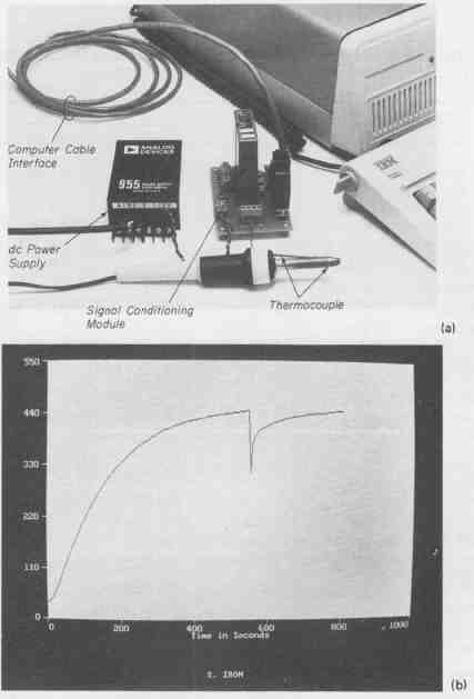
FIG. 5 (a) A single-channel stand-alone, data acquisition system used
to accept soldering iron tip temperature and input this information into
a personal computer; (b) the thermal characteristics of a standard soldering
iron.
- - - - - - -
CONFIGURE GO ANALYZE SAVE RECALL DELETE OPTIONS QUIT
set up data acquisition
- - - - - --
The LABTECH ACQUIRE software is now loaded and ready for the hardware configuration. The thermal profile of a soldering iron will be used as an illustration. For this task, the only main menu options that will be used are CONFIG URE, GO, and QUIT. The ACQUIRE package has more versatility with additional menu options, such as ANALYZE, SAVE, RECALL, and DELETE. These will not be discussed here.
To select from the main menu, press the left or right cursor keys ( ß à) until OPTIONS is highlighted in reverse video. By depressing the carriage return <CR> key, the OPTIONS MENU will be displayed as follows:
- - - - - -
Current Value CGA (4 Colors)
Options Menu
Display Type EGA [8 Colors]
Start on Key Press No
Hold Display on Screen Yes
Hardware Interface Device Demo Board
Analyze Drive, Path Name, File Name C:\Lotus\1 23
Header Records in File? Yes
- - - - - -
Display Type will be highlighted in reverse video. ACQUIRE inspects the system and displays the type of graphics adapter card present within the system.
The UP DOWN (N.) cursor keys are used to move the options menu to high light Start On Key Press. The No is changed to Yes by first depressing the Fl key. A pop-up menu with the Yes No options will appear. The Up Down cursor key is used to highlight Yes and this option is selected by depressing the carriage return <CD> key. A Yes in this field will make the system wait for any key, other than ESC (escape), to be depressed before data acquisition begins. In this way, the beginning of the system receiving data can be controlled by the operator. A No in this field will result in data to be taken the moment that the GO.EXE program is loaded.
The cursor keys are used to highlight Hardware Interface Device. This entry is used to change the designation for the hardware connected to the system. Demo Board and 6B are included in the pop-up menu since there is only one 6Bll module attached. Highlighting 6B and depressing <CR> will select this option.
To return to the main menu, the escape (Esc) key is depressed. The left or right cursor ( keys are used to highlight CONFIGURE. This option is selected by depressing the carriage return key. The Setup menu will be displayed as follows:
- -- - - - -
Current Setting 1
Setup Menu
- - - -
Number of Analog Channels [ .4] 1
Number of Digital Channels 0
Time Stamp Date ? Yes
Sampling Rate (Hz) 10.000
Run Duration 30.000
Starting Method Immediate
Trigger Channel 1
Trigger Threshold 0.000
Trigger Polarity High
File Name TUTOR.PRN
Number of Windows 1
Width of Windows in Seconds 30.000
Window Color Black
- - - - -
Channel Number 1
- -
Channel Name Ch. 1
Display in Window Number [ . . 1] 1.
Scale Factor 1 .000
Offset 0.000
Minimum Display Value 0.000
Maximum Display Value 10.000
Trace Color RED.
- - - - -
The Up Down cursor keys are used to move this setup menu down until Sampling Rate (Hz) is highlighted. The number on the menu is changed to 1 (one sample per second) by typing 1 <CR>. Next, Run Duration is highlighted and the setup number is changed to 800 <CR>. The system is now ready to take data once every second for 800 seconds or about 13 minutes.
Dropping to File Name, IRON <CR> is entered. For Window Width in Seconds, the horizontal axis of the graph is matched to the run duration by typing 800 <CR>. At Window Color, Key F1 is depressed and a pop-up window with eight colors will appear on the screen. The Up Down cursor keys are used to highlight white and are selected by depressing <CR>.
Finally, Maximum Display Value is highlighted and the setup value is changed by typing 550 <CR>. The vertical axis is now limited to 550°C.
The configuration of the display is complete. To return to the main menu, ESC is depressed. To initiate GO (i.e., load the GO.EXC program), <CR> is de pressed when GO is highlighted in reverse video. Any key can then be depressed at the same time that the soldering iron is plugged in. As shown in FIG. 5a, data on tip temperature (° C) as a function of time (seconds) begins to be collected.
The thermal characteristic curve of the soldering iron is shown in FIG. 5b. This curve shows that the soldering iron reached a maximum tip temperature of 440°F in 500 seconds. At —500 seconds, the iron was wiped on a dampened sponge to simulate an actual soldering operation. Tip tempera ture dropped quickly to about 300°F, and recovery time to restore it to 440°F was about 200 seconds.
The exit ACQUIRE, the ESC key is depressed to recall the main menu. QUIT is highlighted and the carriage return <CR> is keyed. A system similar to the one just described greatly simplifies the task of data collection and display.