AMAZON multi-meters discounts AMAZON oscilloscope discounts
LEARNING OBJECTIVES:
Upon completion of this section on preparing detailed drawings, the student should be able to:
1. Make accurate measurements using common precision instruments such as scales, calipers, and micrometers.
2. Use common drafting equipment to prepare good-quality drawings.
3. Use templates in producing sketches and drawings.
4. Know the basic line conventions.
5. Know the four basic dimensioning techniques.
6. Produce engineering sketches.
7. Produce assembly drawings showing a variety of views.
0. INTRODUCTION
Once the preliminary plans for a package are completed and sketches of the chassis configuration are prepared, detailed drawings must be developed to aid in construction. These drawings entail the final positioning of all components and hardware. Sizes of these components and hardware items are first measured to obtain overall dimensions necessary to select and complete optimum orientation and position. Many of these measurements will also determine the size and location of mounting holes during the fabrication of the chassis. These detailed drawings must include all pertinent information with respect to component assembly and positioning and chassis fabrication and finish. It is important to mention here that someone other than the technician who designed the original package may be assigned the task of construction. For this reason, the drawings must be completely informative, accurate, and perfectly clear.
This section contains specific information on techniques of using measuring instruments such as scales, calipers, micrometers, and templates. Also included is relevant information on engineering sketches, basic drafting equipment, drafting standards, dimensioning, and procedural information for developing chassis layout drawings along with assembly and auxiliary views for detail work.
1. MEASUREMENTS WITH A SCALE
In the planning stage, approximate positioning of components and hardware was estimated by physically placing the components in the desired locations. This procedure is shown in the example package of FIG. 1. From this preliminary method, component density can be observed. It is now necessary to take all dimensions from the final component locations and transfer this information to a sketch. These resultant sketches will be used to produce the working drawings.
To obtain most of the required measurements, a simple steel scale is commonly employed. Steel scales are available in a variety of styles, including steel tape rule, steel rule, and hook rule. The 6- and 12-inch steel rules and the 6-inch hook rule are the types commonly used in electronic construction ( FIG. 2). The major scale division on these rules is the inch, with half, quarter, eighth, sixteenth, thirty-second, and sixty-fourth subdivisions. Steel scales are also avail able with decimal graduations having major and minor divisions of 0.1 inch and 0.020 inch, respectively. This rule is desirable when the dimensioning format of the sheet metal drawings is in decimal form. The smaller graduation scales are used where close tolerance measurements are required.
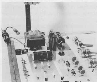
FIG. 1 Overall height, width, and depth dimensions for the chassis
are determined directly from the component layout.
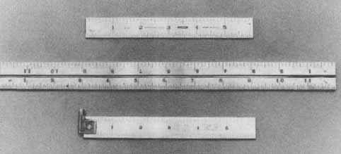
FIG. 2 Steel rules.
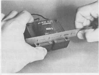
FIG. 3 Method for determining on-center dimensions.
Overall length and depth measurements for the chassis determined by the final component layout can be made by alternately positioning and reading the scale along the lines bounding the area previously established in the planning stage. The height of the unit is determined by reading the vertical measurement of the tallest component together with the desired enclosure clearance. This measurement must be added to the height of the base or main chassis to determine the overall height of the finished unit. The measurement techniques just described are shown in FIG. 1.
Component measurement for mounting purposes can also be made with a scale. As an example, a method for determining on-center dimensions for mounting holes is shown in FIG. 3. Mounting information, however, is usually provided by the manufacturer in the form of a paper template.
For maximum accuracy when using the 6- or 12-inch steel rule, the scale should be positioned perpendicular to the surface being measured. In this way the graduation marks on the scale will be in direct contact with the work and will eliminate the possibility of error due to the thickness of the rule if it is placed flat on the work. In addition, neither end of a rule should be used as the reference or starting edge. For accurate measurements, the work should be aligned with the first major inch graduation mark. This assures that scale-edge deformities will not cause errors.
The hook rule, shown in FIG. 2 (bottom), provides an accurate reference edge along the inside face of the hook. Thus, the zero graduation mark is perfectly aligned with the edge of the work, assuring more exact measurements. It can also be used for rapid settings of inside calipers, as discussed in Sec. 2.
2. MEASUREMENTS WITH CALIPERS
Although rules are adequate for most measurement applications, calipers are necessary if direct measurements are impossible. Calipers are classified as out side or inside, depending on the shape and position of the legs as well as their specific use. Both types are shown in FIG. 4. The main parts of the caliper are the legs, spring crown, and adjusting knob.
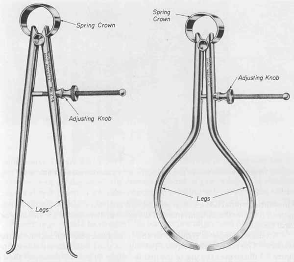
FIG. 4 Inside and outside calipers. Courtesy of the L.S. Starrett Company,
Athol, Mass.
The outside caliper is readily adaptable to measuring diameters of round stock, such as the shaft of a potentiometer or switch. This caliper is held by the spring crown cupped in the palm of one hand with the thumb and forefinger free to apply a rotational force to the adjusting knob ( FIG. 5a). Rotating the adjustment knob will close the legs of the caliper on the surface to be measured. Once the inside tips of the legs contact the surface to be measured, a back-and-forth motion of the caliper along the surface will indicate the correct measurement. The calipers are set properly if there is a slight friction as the inside tips of the legs move across the widest portion of the work. Practice is necessary to acquire the correct “feel” for this optimum setting. With the leg spacing set, the measurement can now be determined by placing the caliper along the edge of a scale and reading the distance between the inside of the legs. This procedure is illustrated in FIG. 5b. Drill gauges can also be used as a quick means of measuring round bodies such as diodes, transistors, and integrated circuits. FIG. 6 shows the measurement of the outside diameter of a transistor using a drill gauge.
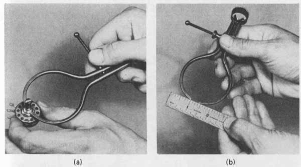
FIG. 5 Outside calipers used to measure round stock: (a) correct method
of setting caliper tips; (b) distance between tips is determined with
a steel rule.
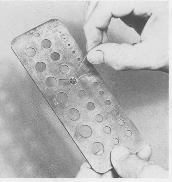
FIG. 6 Drill gauge used to measure the case diameter of a transistor.
An inside caliper is required to obtain and transfer dimensions of inside distances. The procedure is equivalent to that used with the outside calipers. FIG. 7 illustrates the use of the inside caliper. If greater accuracy than can be obtained from the basic caliper is required, dial calipers are used. The 6-inch dial caliper is common in electronic construction. This precision instrument consists of two pairs of jaws (one for inside and one for outside measurements), a dial indicator, and a thumb adjusting knob. This instrument is capable of ac curacies from 0.001 to 0.0001 inch ( FIG. 8). Before using the dial caliper, a zero check should be made to determine if the dial indicator is properly calibrated with the jaws. First, the contacting surfaces of the outside jaws are wiped clean with a soft cloth to remove any foreign matter or dust. The thumb adjustment screw is then rotated clockwise to close the outside jaws. The dial indicator should read zero when the jaw surfaces make contact. If not, the rack and pin ion must be adjusted. The two securing screws at both ends of the rack gear are loosened and the rack is slowly moved until the dial indicator reads exactly zero. The securing screws are tightened and the instrument is set for accurate measurements. FIG. 9 illustrates the proper method of supporting the dial caliper when making measurements. With the adjusting knob rotated to close the outside jaws on the work, the correct amount of jaw pressure is obtained through a slipping action whereby continued rotation will result in the adjusting knob slipping with no further forward motion imparted to the jaws. This action eliminates damage to the caliper and also measurement error.
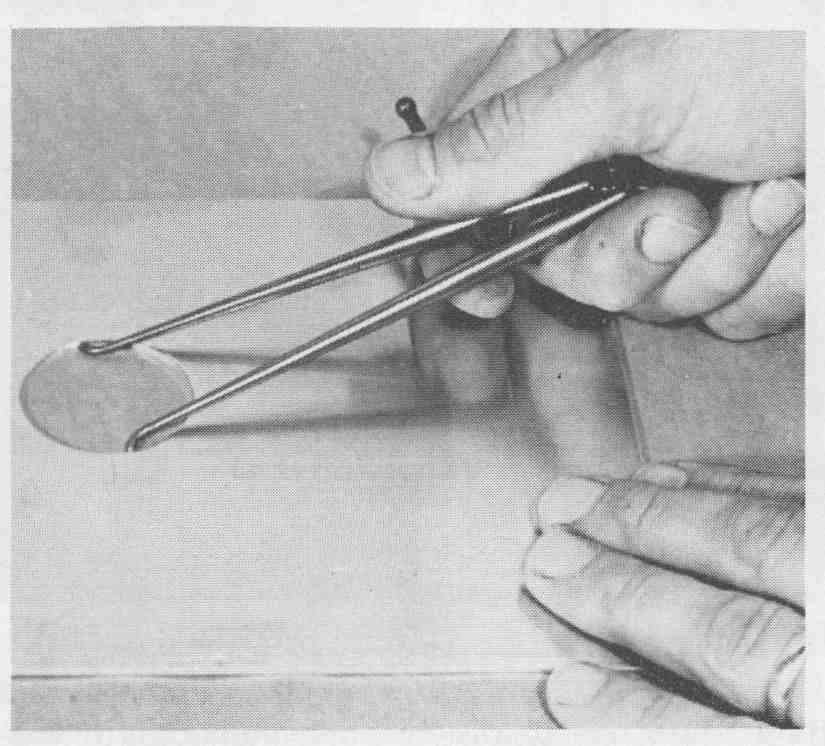
FIG. 7 Correct method of setting inside caliper tips.
All settings should be checked for correct jaw alignment before measurements are read. To ensure accuracy, the jaws of the calipers are slightly rocked over the work (see FIG. 9). The minimum deflection of the dial pointer will result in the most accurate reading.
3. MEASUREMENTS WITH A MICROMETER
The micrometer, like the dial caliper, is capable of measuring to accuracies of 0.00 1 inch and estimates to 0.000 1 inch. The 1-inch outside micrometer is typical, although larger-capacity micrometers are available in addition to special- purpose micrometers, such as screw-thread measuring instruments.
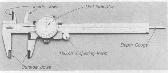
FIG. 8 Dial caliper.
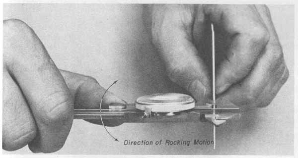
FIG. 9 Dial caliper used to obtain accurate measurements with rocking
motion to determine minimum reading.
The 1-inch micrometer is used primarily to measure diameters and thick nesses. This micrometer, shown in FIG. 10, consists of a frame, anvil spindle, barrel thimble, and ratchet stop. The proper use of this micrometer is as follows. The little finger is hooked around the frame while the thumb and forefinger of the same hand are free to rotate the thimble ( FIG. 11). Clockwise rotation of the thimble will close the spindle on the anvil, which is rigidly supported to the frame. Counterclockwise rotation of the thimble widens the distance be tween the spindle and the anvil. The work to be measured is held in the other hand and placed on the anvil. The thimble is rotated to close the spindle on the work. Once the spindle makes light contact with the work, the thumb and fore finger are moved to the ratchet stop. Clockwise rotation of the ratchet stop for two “clicks” will apply the correct amount of pressure to the work. Excessive pressure may damage the finely threaded spindle or mar the machined surfaces of the anvil and spindle, thus causing measurement errors. It is good practice to maintain continuity in measurement by duplicating the applied pressure. The two “clicks” of the ratchet stop will assure this duplication of pressure.
The spindle has a precision of 40 threads per inch. Thus, one complete rotation will move the spindle exactly or 0.025 inch. Each minor graduation mark on the barrel scale is therefore equal to 0.025 inch. Each major numbered division on the barrel scale represents 0.100 inch, requiring four complete turns to move from one major numbered division to the next. The thimble has 25 graduation lines. Each line represents or of an inch, or 0.00 1 inch. Therefore, as the thimble is rotated from one division to the next in a counter clockwise direction, the spindle moves 0.00 1 inch away from the anvil.
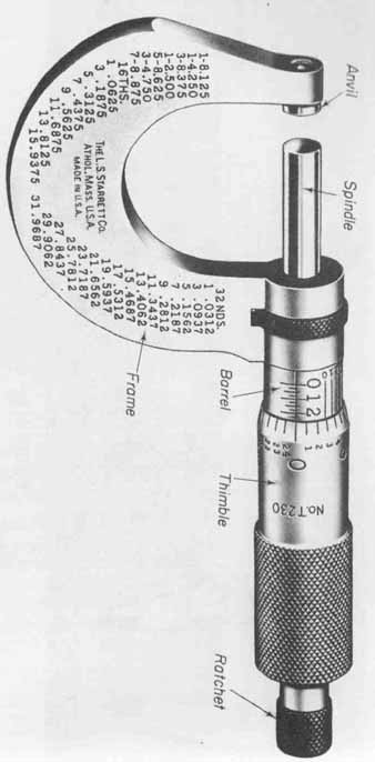
FIG. 10 One-inch micrometer with ratchet stop. Courtesy of the L.S Starrett
Company, Athol, Mass.
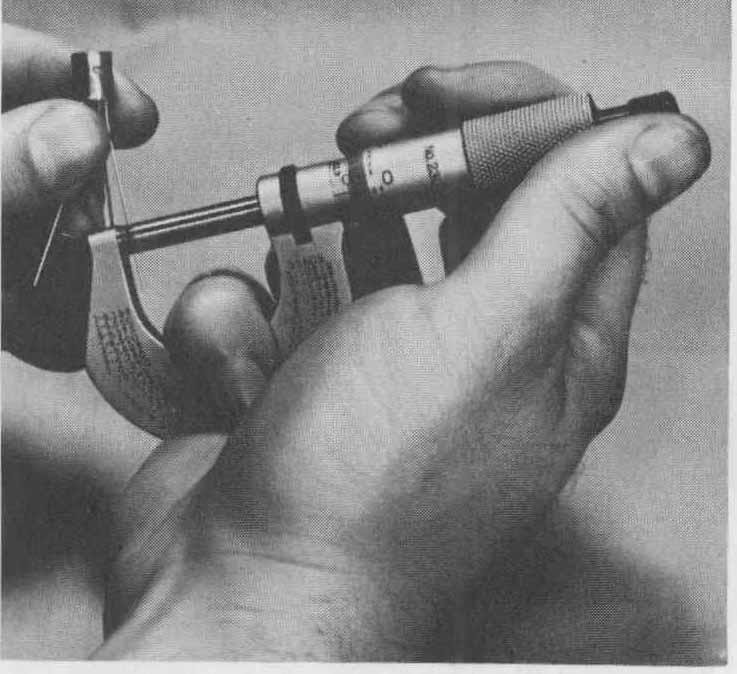
FIG. 11 Correct positioning of the 1 -inch micrometer.
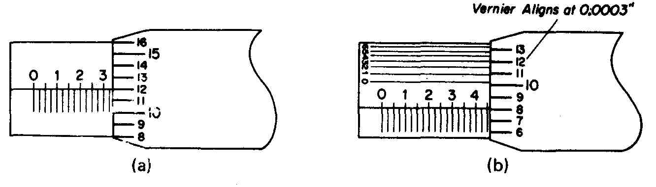
FIG. 12 Illustrations of micrometer scale readings: (a) readings to
the one-thousandth inch using the barrel and thimble scales; (b) readings
to the ten-thousandth inch using barrel, thimble, and vernier scales.
To obtain the spindle-to-anvil opening, three readings are necessary. First, the highest-numbered graduation shown on the barrel is noted. (Each numbered graduation represents 0.100 inch.) The second reading is the number of minor divisions following the major number on the barrel, each minor division representing 0.025 inch. The third reading is the lowest-numbered graduation line on the thimble that most closely aligns with the horizontal scale line on the barrel. This value is in one-thousandths (0.001) of an inch and is added to the sum of the preceding readings to obtain the final measurement.
FIG. 12a represents a reading of 0.337 inch obtained as follows:
Reading 1. The largest visible number on the barrel is 3, or 0.300 inch.
Reading 2. The number of smaller graduations after the number 3 is 1, or 1 x 0.025 = 0.025 inch.
Reading 3. The lowest number of the graduation lines on the thimble that most closely aligns with the horizontal scale line on the barrel is 12, or 0.012 inch.
The sum of the three readings is 0.337 inch.
Some micrometers are equipped with a vernier scale to extend the measurement accuracy to one ten-thousandths (0.000 1) of an inch. This vernier scale is immediately above the barrel scale and its graduation marks extend along the barrel to the thimble scale. The vernier and thimble scales both run horizontally. Each of the 10 graduation lines of the vernier scale, marked 0 to 9, represent 1/10 of the value of the divisions on the thimble scale—that is, of which equals 1/10,000 (0.0001) inch.
To obtain a reading with a micrometer equipped with a vernier scale, the previously discussed three readings are first taken. The fourth reading is obtained by noting which graduation line of the vernier scale aligns with any line on the thimble scale. This reading, in one ten-thousandths (0.0001) of an inch, is added to the sum of the other three readings. FIG. 12b represents a reading of 0.4583 inch, obtained as follows:
Reading 1. The largest visible number on the barrel is 4, or 0.400 inch.
Reading 2. The number of minor graduations after the number 4 is two, or 2 x 0.025 = 0:050 inch.
Reading 3. The lowest number of the graduation lines on the thimble that most closely aligns itself with the horizontal scale line on the barrel is 8, or 0.008 inch.
Reading 4. The number of the division on the vernier scale that aligns with a division on the thimble is 3, or 0.0003 inch.
The sum of the readings is 0.4583 inch.
4. ENGINEERING SKETCHES
A preliminary step in the preparation of the finished drawings is the development of engineering sketches. FIG. 13 shows a sheet metal sketch of the amplifier’s front panel. Using quadruled paper eliminates the need of special drafting equipment and at the same time results in a relatively clear picture. Notice that the engineering sketch shown in FIG. 13 contains not only dimensional information but specifications for finish, type of materials, labeling, and hole positioning. Also useful are manufacturer’s specifications that provide hole-spacing information for mounting holes, pin sizes and configurations, case dimensions, and other pertinent information to aid in layout. Examples of this type of hardware information are available in Google, which includes some of the common solid-state case configurations currently employed in industry.
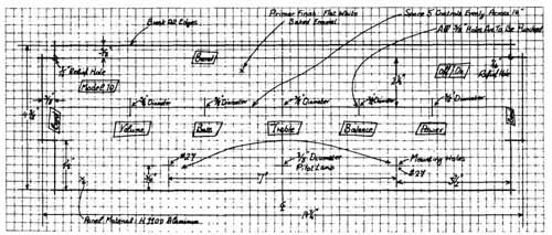
FIG. 13 Engineering sketch of amplifier’s front panel.
5. DRAFTING EQUIPMENT
To produce good-quality drawings, the technician must have available a mini mum selection of drafting equipment and materials and a basic understanding of their function. Tools common to the draftsperson are (1) pencils, (2) drawing boards, (3) T-squares, (4) triangles, (5)protractors, (6) engineering scales, and (7) compasses. FIG. 14 shows a basic drafting setup.
Pencil lead is available in a variety of grades from extremely hard lead for fine light lines to soft lead for dark bold lines. Selecting the proper lead grade depends primarily on the application. Hard leads range from 4H to 9H, the larger number indicating the harder lead. Those leads in the upper half of the range are normally used for diagrams, charts, and graphical computations where extreme accuracy is of prime concern. The lower half of this range represents leads that can be used for line work on engineering drawings, but they have limited application because the lines they make tend to be too light. Medium lead grades are B, HB, F, H, 2H, and 3H. These leads are for general- purpose work in technical drawings. The grades in the upper half of the range are used primarily for line work; grades H and 211 find wide application on pencil tracings for blueprints. The leads in the lower half of the medium range are used for technical sketches, lettering, and freehand work. Soft leads range from 2B to 7B and are used for artwork and certain full-size detail drawings. These leads should be avoided in technical drawings because they smudge. Lead should be kept sharp to maintain line-width consistency in the work.
Wooden and mechanical lead supports are available. Since the lead in the mechanical or refill type can be interchanged, it is preferred over the wooden type.
Drafting boards are constructed from thoroughly seasoned, straight grained soft wood strips. The top or working surface must be both smooth and a true plane. Both side edges must be perfectly straight and parallel so that either one may be used as a working edge with a T-square. The working edges are joined to the main body using tongue-and-groove joints to prevent warping. A drafting board should be checked for warping prior to its use. This can be done by simply placing it on a flat surface and observing if the board rocks. The working edges of the board should also be tested with a T-square that is known to be in alignment. This test is made by placing the bottom edge of the T-square blade along the working edge of the board. If the board is true, the blade will touch along the entire length. Any defect can usually be corrected by sanding or planing the working edge. The most convenient size of drafting board is 18 by 24 inches. Although larger boards are available, this size is most suitable for electronic drafting.
The T-square is most commonly formed with a blade rigidly attached to the head. The inner side of the head and the edges of the blade serve as the working edges of the T-square. As such, they should be perfectly straight and at exactly 90 degrees to each other. This angle can be quickly tested by using a triangle. T-squares are generally made of hardwood, usually the head of black walnut and the blade of maple. Blades are available lined with celluloid, which resists warping and allows lines to be viewed beneath the working edge. Al though available in various lengths, the 24-inch T-square is suitable for most applications. The T-square is a fragile instrument and should be handled care fully to avoid loosening the head. When not in use, it should lie flat on a drafting board or be hung from the hole on the end of the blade.
In use, the T-square is placed on the drafting board with the head along the left-hand working edge and the blade extending along the surface of the board. In this position, it is used to draw horizontal lines and serves as a reference for positioning triangles and templates.
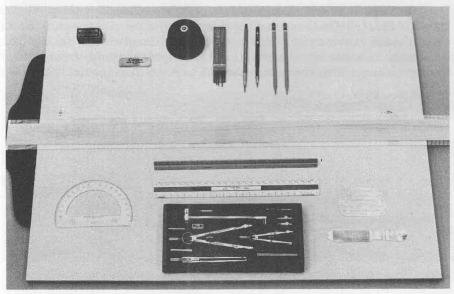
FIG. 14 Basic drafting equipment for electronics.
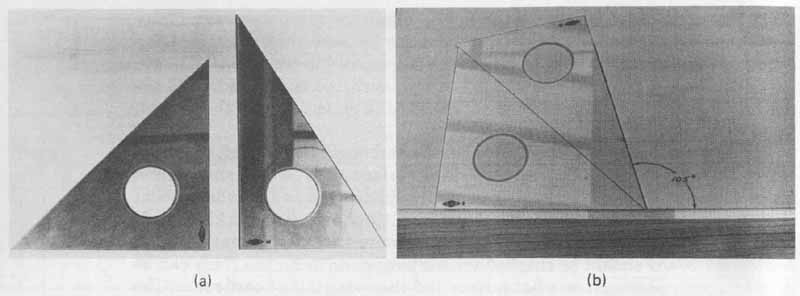
FIG. 15 Drafting triangles: (a) standard 45-degree and 30- by 60- degree
triangles; (b) using triangles in combination to increase layout versatility.
Triangles are necessary to simplify the construction of angles. The most commonly used types are the 45-degree and the 30- by 60-degree triangles ( FIG. 15a). Triangles made of celluloid are considered to be the best quality and are available in different sizes and thicknesses. Most often, they are clear or transparent, but amber, red, and green shades are not uncommon. The most widely used triangles are 0.08 inch thick. The 45-degree triangle with 6- or 8-inch legs used with a 30- by 60-degree triangle with the longest leg 10 or 12 inches long is a suitable combination for many applications. By proper positioning of these triangles, angles of 30, 45, 60, 75, 90, 105, 120, 135, and 150 degrees are easily measured ( FIG. 15b). When angles cannot be obtained with these common tri angles, the protractor is used. For most applications, the clear or shaded celluloid protractor ( FIG. 16) is satisfactory.
Mechanical engineer’s scales are the most useful in electronic drafting ( FIG. 17). These scales provide full-size, one-half, one-fourth, and one-eighth divisions that are satisfactory for most size reductions. Full-divided and open- divided scales are available, on both of which the main divisions represent 1 inch. On the full-divided scale, the basic units are subdivided throughout the length of the scale. On the open-divided scale, only the end segment of the scale is subdivided. Scales are available in either triangular cross section, combining as many as 11 scales, or the conventional flat type having only two scales. The flat type is easier to use because scales can be selected very quickly. Scales are used to obtain full or reduced dimensional ratios. These dimensions can be laid off directly onto the drawing from the scale or by transferring measurements from the scale to the drawing using dividers. Scales are usually made of box wood, and some have white celluloid composition edges.
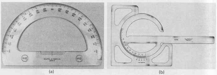
FIG. 16 Protractors. Courtesy of the L.S. Starrett Company, Athol,
Mass.
Drawing instrument sets, such as the one shown in FIG. 14 containing dividers, compasses, and inking pens, are necessary to produce a quality, accurate plate. Occasionally, however, time is more important than precision. The use of templates, such as those shown in FIG. 18, can aid in producing good drawings with a considerable saving of time and effort. Templates are used extensively as a quick means of reproducing electronic symbols and other shapes, particularly circles. They consist of various shaped cutouts in a piece of clear or shaded plastic. When these cutouts are outlined with a pencil or pen, the result is a uniform and neatly shaped electronic symbol or figure. Templates were not intended to replace drafting instruments but to provide a faster means of producing sketches and drawings. The quality and accuracy of a plate produced with drafting equipment cannot be duplicated by using templates.
Knowledge of the size and type of paper used in the drawing is helpful. Commonly available drawing paper sizes are: A-size (8 by 11 inches), B-size (11 by 17 inches), C-size (17 by 22 inches), and D-size (22 by 34 inches). Larger sizes are available, of which K-size (40 by 50 inches) is normally the largest used in engineering work. The paper size is, in many cases, selected to be compatible — with the filing system in use. In all cases, the paper should be of sufficient size to show detail work without crowding, yet not so large as to have excessive unused areas or overly large borders. The preferred paper for electronic drafting is the HP (hot-pressed) cream or buff-colored type. This paper is sufficiently heavy and hard-surfaced to be used for high-grade, accurate detailed work. CP (cold-pressed) paper is less expensive and is used for general drawing or sketching. The surface of this type of paper will not hold up to erasing as well as the HP type. When blueprints are to be made from pencil drawings, a white, light weight bond paper should be used. This type of paper allows blueprints to be produced directly without the need for tracing.
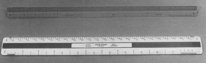
FIG. 17 Mechanical engineer’s scales.
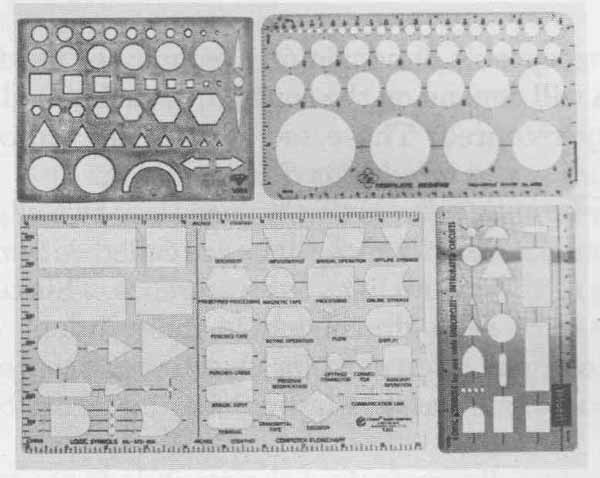
FIG. 18 Drafting and electronic layout templates.
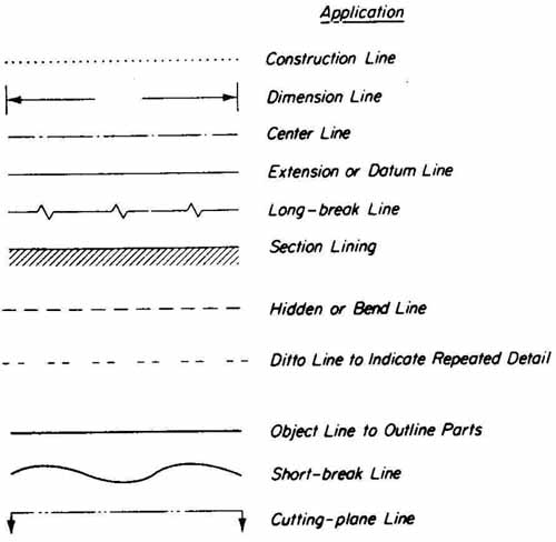
FIG. 19 Basic line conventions used in engineering drafting.
6. BASIC LINE CONVENTIONS FOR DRAWINGS
Since the primary objective in engineering drafting is to transmit detailed in formation pictorially, a basic knowledge of the various types of lines used and their application is essential. The symbolic lines conventionally accepted are shown in FIG. 19. All lines should be made dark with the exception of construction lines. In addition, the line width will vary depending on the type of symbol used. Thin lines are used for dimension, center, extension, long-break, and section symbols. Medium thickness is used for hidden and ditto lines. Thick lines are reserved for object, break, and cutting-plane lines.
7. DIMENSIONING FOR CHASSIS LAYOUTS
There are several acceptable dimensioning techniques used in chassis layouts, the choice of which will depend on the configuration being dimensioned and the degree of accuracy required. These techniques are center-line, continuous, and tabulation dimensioning.
Datum-line or base-line dimensioning uses any two edges that are perpendicular to each other. These reference edges are called datum lines. Each dimension made uses one of the datum lines as a reference. This technique eliminates cumulative error, since each dimension is independent of all others. This method of dimensioning is often used for close-tolerance work, especially when mating parts are to be fabricated. FIG. 20 illustrates base-line dimensioning.
In pure center-line dimensioning, the stock is first equally divided vertically and horizontally. The locations of all holes are made from these reference lines. No other lines are used as a reference. In electronic layout, datum-line dimensioning is preferable when locating holes, since edge reference facilitates this layout, as described in Section 5.
When holes are to be formed that match a particular pattern on a component, such as the mounting holes on a speaker, a variation of pure center-line dimensioning is preferable. Base-line or pure center-line dimensioning would create a larger tolerance in this application. For this reason, independent dimensioning of related holes or of hole patterns should be avoided. In this technique the center of the largest or major hole in the pattern is located from datum lines. All other hole centers are dimensioned using these major hole center lines as a reference. FIG. 21 shows an example of center-line dimensioning.
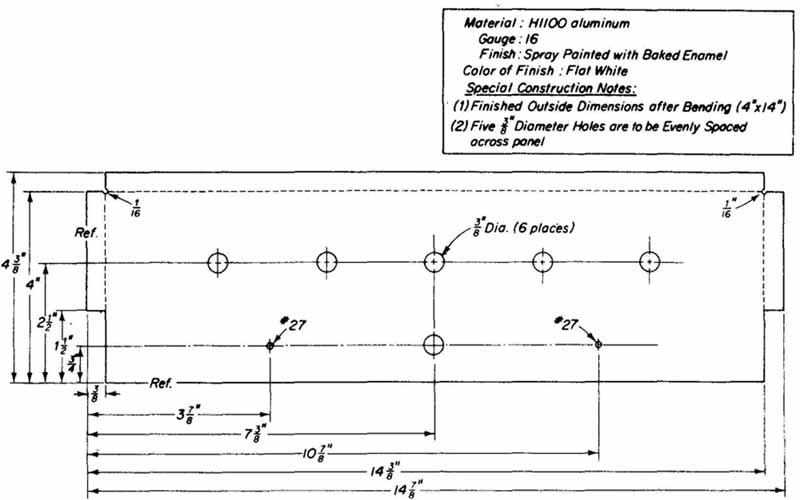
FIG. 20 Base-line dimensioning of the amplifier’s front panel.
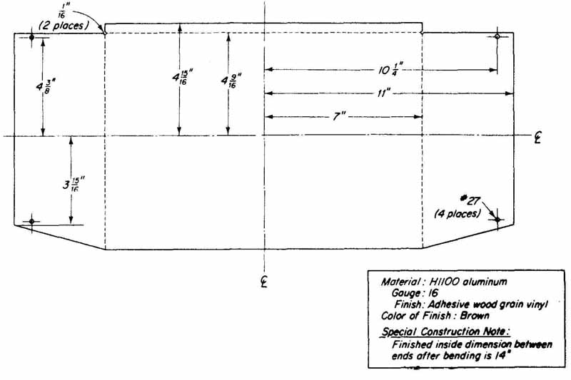
FIG. 21 Center-line dimensioning of the amplifier’s enclosure element.
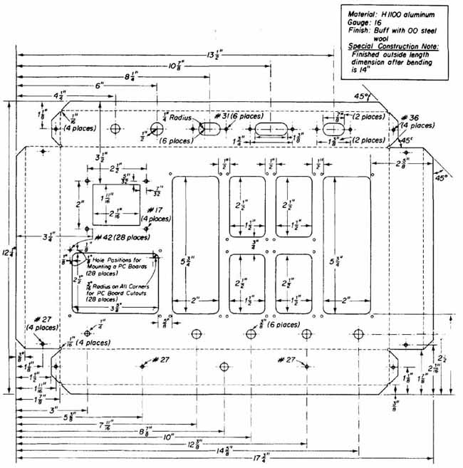
FIG. 22 Amplifier main chassis element layout.
As drawings become more complex, it is necessary to use both datum-line and center-line dimensioning, especially when the exclusive use of either one would adversely affect clarity. FIG. 22 shows an example of combining both techniques on one drawing. Notice that the use of both techniques reduces the number of dimension lines crossing. Although it is acceptable practice for dimension lines to cross, dimensions may become difficult to read if this practice is used extensively.
When tolerances are not critical, continuous dimensioning may be used. Shown in Fig 22, and is commonly used in combination with center-line dimensioning. This technique of dimensioning can cause large tolerances and should be used only when critical dimensions are not required.
When dimensioning complex, high-density hole patterns, hole-center locations may be presented in tabular form, with no dimension lines shown on the drawing. Two datum lines are selected and identified with an appropriate designation, such as X and Y, for the horizontal and vertical datum lines, respectively. All hole centers are then identified literally, the same designation being used for common-size holes. A table identifying each hole, with its size and distance from each datum line, is then prepared and attached to the drawing.
When a high degree of dimensional tolerance is required, measurements should be taken in decimal form. Since this degree of accuracy is not normally required in prototype construction, fractional measurements are used through out this section. With fractional dimensioning, accuracy to inch is easily obtainable. Maximum allowable variation above and below the nominal value by which the given dimension may differ from the drawing to the actual work appear with the dimension where applicable.
8. ASSEMBLY DRAWINGS
After a prototype has been completed, final drawings and photographs are made of all assemblies and subassemblies. These drawings may be of several variations: two-dimensional top, bottom and side views; three-dimensional views; isometric projections; and exploded views. The designated views must contain all pertinent information concerning the proper location and orientation of each component and mechanical part. All parts shown in assembly drawings should be identified and labeled consistent with the designations used on the schematic diagram. A common arrangement is a numbering system relating to the parts and accompanying the drawings.
Auxiliary views are frequently necessary, especially when complex or high-density packaging obscures some of the major sections of the package. An auxiliary view is a drawing of the obscured portion of the package after eliminating obstructions of the primary views. FIG. 23 shows a partial assembly layout for the amplifier package, including an auxiliary view.
Photographs are particularly advantageous because of their high quality and three-dimensional perspective characteristics. In addition, nomenclature and reference information can be superimposed on photographs. Drawings, however, are absolutely indispensable for fabrication, assembly, and wiring because of the excessive amount of explanatory information necessary.
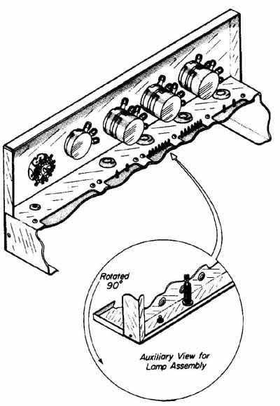
FIG. 23 Front panel assembly drawings.
The next phase of construction after the drawings have been completed is to shear the chassis elements into the desired blanks. In the following section, detailed procedures for shearing sheet metal are presented. Specifically, the amplifier chassis elements, as shown in the drawings in this section, are blanked and prepared for layout.
EXERCISES
A. Questions
1 How should a scale be placed when measuring the distance between mounting holes to obtain an accurate on-center dimension?
2 Why is it not advisable to use the end of a rule as a reference when taking measurements? What reference should be used?
3 Describe three methods for obtaining the diameter of round components.
4 How many steps are required to obtain the reading using a micrometer equipped to read to one ten-thousandth of an inch?
5 What information is shown on an engineering sketch?
6 How are the sizes of drafting paper designated?
7 What type of drawing paper is preferred for electronic drafting?
8 Describe each of the following dimensioning techniques:
a. Datum-line
b. Center-line
c. Continuous
d. Tabulation
9 Which dimensioning technique results in large tolerances?
10 When a high degree of dimensional tolerance is required, in what form should measurements be taken?
11 Describe the information that is conveyed on a drawing by the width of the lines used.
12 When are auxiliary views on a drawing required?
B. True or False
Circle T if the statement is true, or F if any part of the statement is false.
1 The thimble on a micrometer has 25 divisions, each representing 0.010 inch. T F
2 Engineering sketches are easily produced using quadruled paper without the need of special drafting equipment. T F
3 Pencil grades 3H to B are suitable for general-purpose work in technical drawings. T F
4 As paper size increases (i.e., A B C D), the height and width dimensions double. T F
5 Datum-line dimensioning uses any two reference edges that are perpendicular to each other.
6 When tolerances are critical, continuous dimensioning is used.
7 Nine different angles can be obtained by using a 45-degree and a 30- by 60-degree triangle in combination with a T-square.
C. Multiple Choice
Circle the correct answer for each statement.
1 For maximum accuracy in taking measurements with a scale, the work should be aligned with the (end first major graduation) of the scale.
2 Micrometers are capable of measuring accurately to (0.0001, 0.001) inch.
3 Engineering sketches should be produced on (plain, q paper.
4 Another name for base-line dimensioning is (datum, tabulation).
5 It is (ac not acceptable) to combine several dimensioning techniques to achieve clarity.
6 When dimensional tolerance is not critical, (center-line, continuous, base line) dimensioning may be used.
D. Matching Columns
Match each item in column A to the most appropriate item in column B.
COLUMN A | COLUMN B
Engineering sketch Micrometer Outside Subdivisions Steel scale Dimensioning Assembly drawing Vernier |
a. Spindle, anvil b. Continuous c. 1/10,000 inch d. Isometric projections e. Caliper f. Quadruled paper g. ¼,1/8,1/16,1/32” h. Hook rule |
E. Problems
1 Read the measurements shown in Figs. 3 and.5b.
2 Read the micrometer setting shown in FIG. 10 and those in FIG. 24.
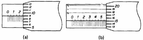
FIG. 24
3 Read the vernier caliper settings shown in FIG. 25.
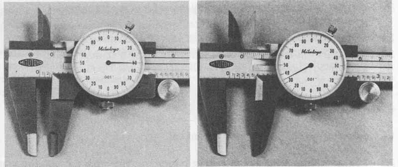
FIG. 25
4 Measure the body and lead diameters and body lengths of 0.25-watt through 10-watt resistors. Also determine the body and lead diameters of several electrolytic capacitors and the body thickness and lead spacing of various- sized disc capacitors. Tabulate all measurements for future reference.
5 Construct the engineering drawings, chassis element layouts, and assembly drawings for the package designed in Problem 2.1.