The topic this month is 'Robodynamics and the Hobbyist', as H.W. Gleaves takes up our offer to use these pages for an exchange of ideas.

Arobot is a complex system not unlike an automatic instrumentation system. It is a combination of a number of basic units, ie data processor (DP), mechanical superstructure, electronic signal processors, transducers and so on, the aim being to produce a machine that is general purpose in nature and capable of performing physical tasks in the same way that computers perform mental tasks. Since one cannot perform any physical task without some form of mental effort, it follows that any good robot will need to incorporate a computing ability.
A block diagram of a typical robot is shown in Fig. 1. Of course, not all robots will take this form--not all will possess a ...
---------
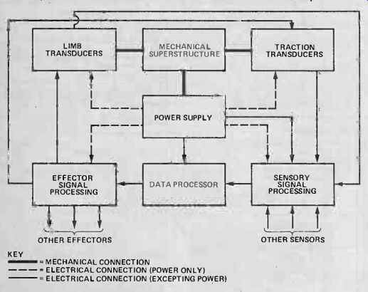
LIMB TRANSDUCERS MECHANICAL SUPERSTRUCTURE TRACTION TRANSDUCERS ; POWER SUPPLY; EFFECTOR SIGNAL PROCESSING DATA PROCESSOR SENSORY SIGNAL PROCESSING OTHER EFFECTORS OTHER SENSORS KEY
MECHANICAL CONNECTION
ELECTRICAL CONNECTION (POWER ONLY)
ELECTRICAL CONNECTION (EXCEPTING POWER)
Fig.1 Block diagram of a 'typical robot'.
-------------
... limb, for example. However you design your robot it will, more than likely, take the form shown and therefore a brief description of the function of each sub-assembly (and guidelines for its design) will now be given.. Mechanical Superstructure This is required to support all of the internal components, such as motors, batteries, electronic circuit boards, and so on. It is responsible for holding the robot together! It also serves the often ignored function as a 'bed' or base for mounting the sensors and, as such, the geometry of the mechanical superstructure is very important, since the software used in the DP will also depend on this. Great attention should be paid to the design of the mechanics since, unlike an electronic circuit, modifications are (usually) not easily carried out.
I have found during my involvement with robots that the guiding principle in such a project is efficiency. Because the robot will have to depend on its own power supply, it is logical to optimize things so that it will obtain the maximum operating time from its batteries and the factors affecting this parameter are chiefly mechanical in nature. For example, the robot's center of gravity should be designed to lie directly over the driving wheel axis, since wheel slip will be thus reduced.
Power Supply
An ideal robot would contain two supplies- -one for the chiefly electronic units, and another for the chiefly mechanical units. This is because the electromechanical parts apply a greater load to the power supply and the voltage drop introduced into the electromechanical supply could drastically affect the performance of the circuitry.
The type of supply used will be some form of battery, although in a number of cases an umbilical cable could be used.
Lead-acid batteries are favored, due to their good power-to -weight ratio, although nickel cadmium cells can be employed for units which require less power since these cells require less maintenance.
Sensory Signal Processing
This is one of the most interesting aspects of robot design: its purpose is to provide conditioning of the signals from the multitude of transducers on the robot, ie analog-to-digital (ADC) conversion. It will also consist of a switching pack, to enable the DP to access any one of the sensors. Many types of sensors can be added to a robot, eg ultrasonic ranging (discussed later), temperature sensing, and force sensing (also discussed later), each supplying data to the DP.
Effector Signal Processing
The function of this particular unit is to convert the digital data from the DP into signals capable of operating the robot's effectors, ie its traction motors and its limb drive motors.
You must be aware that the robot must possess more sensors than effectors since it is an unwritten law that much more data goes into a system than comes out of it! Effector signal processing covers such things as digital-to-analog conversion, and motor speed control.
Data Processing
A more apt title for this device would probably be 'data converter', since that is its primary function in a robot. The object is that for every type of data entering the system, there should be corresponding data coming out. The relationship between data out and data in is complex, and is wholly determined by the software contained in the DP. It is a good idea to develop the software for your robot simultaneously with the hardware, since deficiencies in one aspect can be taken up in the other.
Robot Sensors
A robot needs to have a lot of information entering it per unit time in order to make useful deductions about its environment. It is for this reason that I decided to try and make an accurate ultrasonic ranging system.
I knew the theory, since enough people had talked about it, but nobody seemed to be able to produce a working system good. enough to use. I therefore embarked upon the design of a circuit which, in conjunction with the DP, would enable the robot to determine the range of obstacles path.
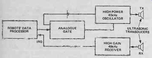
Fig. 2 Block diagram of an ultrasonic ranging system.
After much experimentation, a working system was put together and with it the robot could measure ranges up to a distance of nearly 2 m, to an accuracy of ± 2 mm.
The principle is described in Fig. 2. As can be seen, the high power ultrasonic oscillator has its supply wired in series with an analogue transmission gate and can be started and stopped by means of the logic control input. This input is connected fo, and controlled by, the robot's DP. The high gain ultrasonic receiver is a combination of op-amps, designed to both amplify and filter the sound.
The whole assembly is controlled by the DP, which, as well as starting and stopping the transmitter, performs the additional function of counting (at a high rate) until sound reaches the receiver, whereupon it stops --the value counted being in proportion to the target's range. In the system presently in use, it is the 'interrupt request' input that is used, rather than just the 'interrupt', because the interrupt request, or IRQ, can be ignored by the DP and this prevents the DP being triggered when the ranging system is not in use.
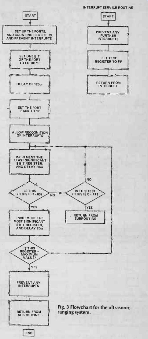
Fig. 3 Flowchart for the ultrasonic ranging system.
Interruption Control
The DP only activates the IRQ during the 'listening' period immediately following the switching 'off' of the transmitter. It is during this time that the burst of sound is travelling towards anything in the robot's path and if there is anything sufficiently close then the reflected sound energy will interrupt the DP. It will then start an interrupt service routine, the purpose of which is to inform the main program that a signal has been received and it is time to stop counting. This terminates with the range data safely stored somewhere in the RAM, ready for further processing. The software for the system can be grasped by reference to Fig. 3.
In the program, the most significant register is compared with a value called 'max'; this corresponds to the maximum range that either the system operates at, or that you wish to detect targets up to- -it limits the value counted to by the DP. The circuits for both the receiver and the transmitter are shown in Fig. 4. In the prototype, one PCB was used for both circuits. Care should be taken to prevent the receiver being affected by the transmitter.
The system should be set up using a multimeter. First energize the 'send' line continuously, to give a constant 40 kHz, and place the transducers about three inches apart, facing in the same direction. Place a suitable target in front of the transducers, about six inches away. Using the meter, monitor the output of the receiver and adjust the sensitivity control until the output voltage drops to approx 0 V. If the target is now moved away, the voltage should return to 5 V (approximately). At this stage all that remains is to adjust the frequency control of the transmitter to obtain the maximum range, and this is done by performing the above procedure, but at gradually increasing distances. In the prototype a maximum range of about 4 m was achieved, but the positioning and orientation of the target were so critical that advantage could not be taken of this and the maximum usable range of 1 m was found to be entirely sufficient in any event.
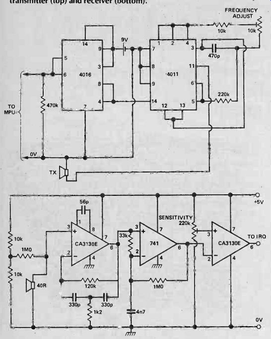
Fig. 4 Suggested circuit for an ultrasonic transmitter (top) and receiver
(bottom).
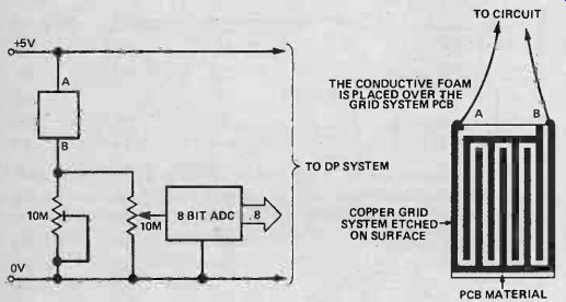
Fig. 5 Experimental force sensor.
Force Sensing
This is the ideal device to use in a robot hand or gripper, since with it the robot acquires the sense of touch. It is very sensitive, being able to detect even the slightest change in applied force, and it also has exceptionally good repeatability, although there is a 'recovery time', after the sensor has been compressed and then released, of about one second in duration.
The heart of the system is a piece of conductive foam of the type used with CMOS ICs. This foam is conductive--in fact the average piece has a resistance (between its two ends) of a few Megohms. The important point about this foam, however, is not the fact that it is conductive, but the fact that its resistance changes if a compressive force is applied to it (as it is compressed its resistance drops). Using a simple circuit, a voltage can be derived that is proportional to the resistance of the foam, which is related to the V force applied to the foam. This voltage can then be converted (using an ADC) to give the robot's DP accurate information about the applied forces. A simple circuit for you to experiment with is shown in Fig. 5; here the data information sent to the computer increases as the force applied to the sensor rises.
A Drunken Robot?
A major problem is a robot's inability to move in straight lines. This is brought about by the robot's drive wheels rotating at different speeds due to things like differences in instantaneous wheel load and friction. The combination of all these apparently minor effects, is to cause the wheels to rotate at unrelated speeds, a feature now known to be highly undesirable.
There are two approaches to solving this problem: computer intervention or use of a hardware lock circuit.
Both these ideas have been worked out on paper and the computer intervention method is preferred, because it is more accurate and uses the DP rather than hardware.
A block diagram of the computer intervention method of wheel control is shown in Fig. 6. The DP energizes the 'sensor select' input and this has the effect of connecting one of the sensors to the tachometer circuit. (The tachometer could well be the one given in the November issue of ETI in the 100 Circuits Supplement.) The output from here will be a square-wave, the frequency of which depends on the angular velocity of the motor shaft. This frequency is converted into a voltage, and then into an eight-bit word, which is entered into the DP, The DP can thus get an accurate digital representation of the angular velocity of each motor (and hence wheel). Using some specially written software these two numbers can be processed and another number computed, which is then applied to one of the eight-bit rate-multipliers. The output of these is fed to a series switch in the motor circuit. The general algorithm used by the computer will be to find the value of each motor speed and then, if these are different, proceed to slow down the faster of the two. (Trying to speed up the slower of the two could be disastrous if one of the wheels has become jammed somehow!) It should also be possible to ensure that the above process does not result in a gradual reduction of the robot's speed, perhaps by speeding up the slow motor every now and then.
If the wheel had, in fact, been jammed or excessively loaded, its speed could be checked and, if no change had occurred, the faster motor could be slowed down as described above.
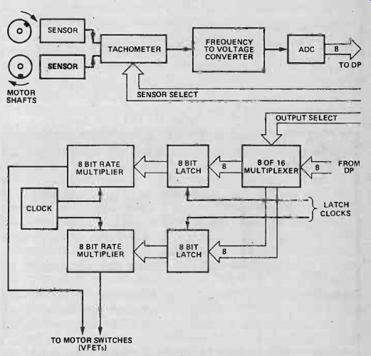
Fig. 6 Block diagram of motor regulation system.
Conclusion
I hope that these ideas will give the readers of ETI something to begin experimenting with. Anyone who wishes to comment on any of the points raised herein can do so by writing to: 'Robotics Today', 145 Charing Cross Road, London WC2H OE E.
This new series will provide a stage upon which our readers may display their robotics achievements. It is intended to cover the practical application of robots in Britain today, be it at hobbyist level or in industry.
Readers in either category are invited to write to the editor of ETI, detailing their experiments, projects, application or usage of robotics. Any articles published will be paid for at commercial rates. It is also hoped to run an 'Ideas Forum' wherein readers can exchange views and ideas but that depends upon the response of our readers --you!
= = = =
Electronics Today (UK print magazine)
Also see: Link |