Peak and average audio levels are indicated by a bar of light.
HIGH-POWER amplifiers usually incorporate meters to indicate the output-power levels in each channel. These meters are often called VU meters but in most cases they resemble proper VU meters only in the way they are scaled.
A professional VU meter is the industry standard for measuring the levels of complex music waveforms. It has a scale marked from -20 to +3 VU (on a steady state signal VU correspond to dB) where '0' VU corresponds to a level of one milliwatt into 600 ohms. The meter has a carefully controlled time constant such that if a reference tone level is applied the pointer of the meter will take 0.3 seconds to reach 99% of the reference level, and will then overshoot by not more than 1.5% and not less than 1.0%. The professional VU meter is thus an instrument that has been designed to give a reasonable compromise between indicating the fast peaks and the average levels of a complex music waveform.
In contrast the meters fitted to some amplifiers have scales calibrated in VU but usually relying on the inertia of the meter movement to provide meter averaging. Apart from this the 0 VU point corresponds to the rated power output of the amplifier - not to 1 mW into 600 ohms (equivalent to 75 mW in 8 ohms). Strictly speaking therefore such meters should be called level or power meters, not VU meters.
Even the best of such meters are not fast enough to indicate accurately the peak levels which occur in music and hence are useless for detecting the onset of amplifier clipping. This is vital as at clipping amplifier distortion rises rapidly.
One alternative is to use in addition to the level meter a clipping indicator that detects fast peaks which exceed a preset level. The ETI 417 OVER-LED project was such an instrument - it flashed an LED when a music transient exceeded clipping level.
The circuit described in this project is best described as a ' level meter'. It uses an array of LED diodes set to illuminate at successively higher increments in music level. With this type of display an estimate can quite easily be made of channel balance, and all transients, no matter how fast, are detected and indicated.
SPECIFICATION
Supply voltage
Supply current
Input sensitivity (VU meter)
Indication
Attack time
Release time 20 to 32 volts dc 15 to 20 volts dc 16 mA dc approx 500 k/v 8 LEDs 3 dB apart 1 ms
0.5 sec.
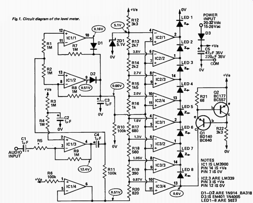
Fig. 1. Circuit diagram of the level meter.
---- NOTES IC1 IS LM3900 PIN 14 IS +Ve PIN 7 IS 0V IC2,3 ARE LM339 PIN 3 IS +Ve PIN 12 IS OV D1-02 ARE 1N914 BA318 D3 IS EM401 1N4005
LED1-8 ARE 5023 VOLTAGES GIVEN ARE OF THE PROTOTYPE BUT SHOULD BE TYPICAL MEASURED WITH 25Vdc SUPPLY AND NO INPUT SIGNAL
DESIGN FEATURES
The ETI 438 Level Meter can be arranged to indicate levels either in 'VU meter' format or in output power format. In the ' VU-meter' format the eight diodes light at 3 dB intervals from - 18 to +3 VU where 0 VU corresponds to the nominal voltage required. Alternately as a power meter (remember that an amplifier cannot be driven beyond the clipping point) the top LED indicates maximum power and each lower LED indicates half the power of the one above it. The LEDs of the meter could thus be labeled,
-----------
HOW IT WORKS - ETI 438
Although the circuitry of the level meter looks complicated the complete instrument only uses three ICs. These are an LM3900 which is a quad amplifier and two LM339s which are quad voltage comparators.
The input signal is amplified and buffered by IC1/3 to provide about 2.5 volts out at 0 VU input. The value of R5 is selected to give the sensitivity required for amplifiers of different power outputs. The gain of this amplifier is equal to the ratio of R9/R5.
A positive peak detector, ICl/1, and an inverting negative peak detector, IC1/2, give an output which represents the absolute peak level.
Capacitor C3 and resistor R10 provide the peak hold and decay time. IC1/4 provides compensation for the 0.6 volt offsets of the LM3900 inputs.
The eight comparators are connected to a resistor divider chain the top of which is fed from a 5.1 volt supply which is stabilized by a zener. The resistor values are calculated to provide reference voltage steps at 3 dB intervals. The output of the detector is applied to all the non-inverting inputs of the comparators.
The LEDs are all connected in series and supplied with a constant current of 10 mA by the source consisting of Q1 and Q2. The outputs of the comparators are via open collector transistors which are "ON" if the input is lower than the reference voltage at the particular comparator input. With no input signal at all the comparators are all on thus shorting out all the LEDs so that none is on.
As the input voltage rises the comparators turn off in sequence allowing the 10 mA to flow through the LEDs. Thus as the voltage increases a bar of light of increasing height is formed by the LEDs.
The current drawn from the power supply is about 16 mA and is independent of the number of LEDs which are on. Supply voltage is not critical and may be anywhere between 20 and 32 volts. Providing the supply is between these limits the unit will also be insensitive to supply ripple. When working from a de supply a 47 microfarad filter capacitor is required but if an ac supply is used then the capacitor should be increased to 220 microfarad to minimize ripple. A single diode is used to both rectify the ac input and to prevent damage due to accidental reversed polarity if a de supply is used.
---------------
for example (for a 100 watt amplifier) 100, 50, 25, 12.5 watts etc.
The fast attack time of the meter (less than one millisecond) ensures that even very short transients are detected, whilst the relatively slow release time (0.5 seconds) provides a reasonably-accurate, average - level indication.
In most previous designs for such meters, discrete transistors were used to build level detectors. Temperature effects and variations in gain led to inaccuracies and to calibration difficulties. These problems have largely been overcome in the ETI 438 meter by using the LM339 IC which contains four accurate level detectors in one package. Additionally the LM339 also has an open-collector output stage which enables a constant current supply for the LEDs to be used. Thus the current and LED brightness are the same no matter how many LEDs are alight.
If required the interval between LEDs may be altered by changing the values of R13 to R20. Thus for example, a 6 dB interval could be used. Additionally the display could be extended to 12 or even 16 diodes by adding comparators and LEDs and by substituting another divider chain for R20 .(values would have to be calculated for the levels required). The positive inputs of the comparators would also be fed from C3 and R10.
A separate current source would be required as there is insufficient supply voltage available to light 16 LEDs in series. If the bottom. LED in such a system indicates a level more than 30 dB down it may also be necessary lo use a trimpot as the bottom resistor of the second divider chain to adjust for offsets etc.
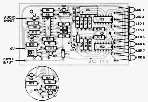
Fig.2. component overlay using 80140 for 01. Circled diagram shows use of alternative BC640
---------------
PARTS LIST
- ETI 438 R21
Resistor 68 ohm R19 " 390 ohm R18 " 560 ohm
R17 " 680 ohm R20 " 820 ohm R16 " R15 " R14 " R13 " R12,22 " R6,10,11
Resistor 100k 1 / 2 W 5% R1,2,7,8 " 1M 1/2W 5% R3,4,9
See Table 11 / 2W 5% R5 See Table 1 1 / 2 W 5% C1 2 3,4
Capacitor
1 uF 35V electro
*cbA, 47 uF 35V electro
*C5B 220 uF 35V electro
* use 47 11F for dc operation 220 uF for ac operation IC1
Integrated Circuit LM 3900 IC2,3 Integrated Circuit LM 339
01,2
Diode IN914, BA318 or similar D3 " EM401, IN4005 or similar ZD1 Zener diode 5.1 V 400 mW Q1 Transistor BD 140, BC640 Q2 BC177, BC 557 LED 1-8 L.E.D. 5023 or similar PC board ETI 438 NOTE: Electronics Today is adopting the European standard method of showing component values- i.e. 1k5 = 1.5k, 2k7 = 2.7k, etc.
1-k 1k5 2k2 2k7 3k3 1/2W 1 12W 1 / 2W
1/2W 1/2W 1 / 2 W V2W V2W V2W V2W
5% 5% 5% 5% 5% 5% 5% 5% 5% 5%
----------------
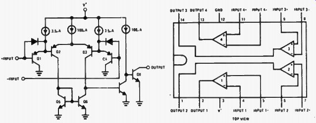
Fig.3. Internal circuitry and pin corrections of the LM339 IC.
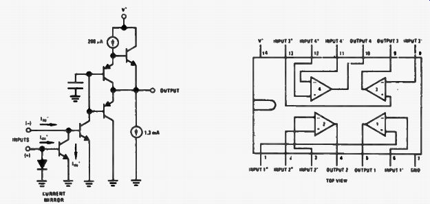
Fig.4. Internal circuitry and pin connections of the LM3900 IC.
The LM3900 is a quad differential amplifier which uses a current balancing technique at the input rather than the voltage balancing that is used with conventional operational amplifiers. Both the inputs " look" like the base-emitter junctions of normal transistors and both are at 0.6 volts with respect to ground. The currents into the two inputs must be equal if the output of the amplifier is to be in the linear region. In the case of IC1/3 the current into the positive input is set at about 12 microamps by R3 and R4. Current into the negative input is provided from the output by R9. If the current into the negative input is too low the output voltage will rise thus increasing the current into the negative input until balance is achieved. This self balancing ensures correct static biasing.
Gain is obtained by feeding a signal into R5 which adds or subtracts current into the negative input. For the amplifier to remain balanced there must be a corresponding shift in output voltage. The voltage gain is the ratio of R9 to R5.
SPECIFICATION
LM3900 Maximum supply voltage Supply current Voltage gain Input current range Current balance Bias current Output current capability 32 V 6 mA typical 2800 V/V typical 1 µA - 1 mA
0.9 - 1.1 at 200
µA 30 nA typical 18 mA source typical.
1.3 mA sink typical
The LM339 is a quad voltage comparator where the output of each is an NPN transistor which has ar unterminated collector and its emitter connected to ground.
SPECIFICATION
LM339
Maximum supply voltage 36 V Supply current 0.8 mA typical Voltage gain 200 000 V/V typical Offset voltage 2 mV typical Bias current 25 nA typical Response time 1.3 µS typical Output sink current &16 mA typical Input common mode voltage range 0 to ( V+ - 2 volts)
CONSTRUCTION
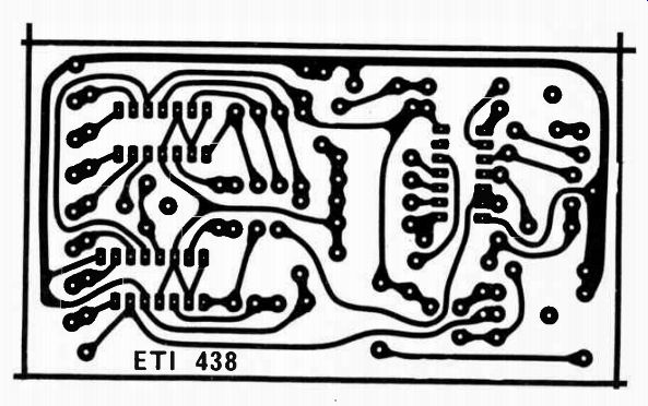
The meter will most likely be mounted in an existing amplifier or piece of equipment and for this reason the board construction only is given.
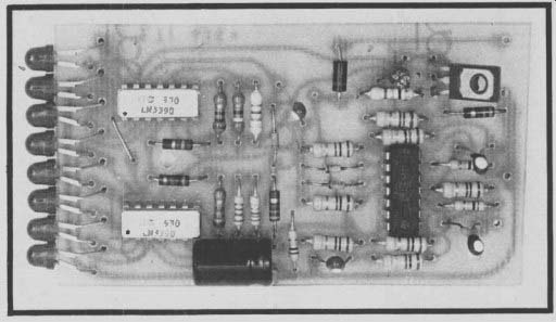
Layout of components is non-critical but, as with any multiple IC device, construction is greatly simplified by using the printed-circuit board specified. The usual precautions with polarities of components, such as capacitors, diodes, ICs and transistors should be observed. Some care must be taken when mounting the LEDs in order to obtain even spacing and good alignment. The long lead of the LED should be inserted in the hole furthest from the edge of the board. Put a slight curvature in the leads so that the LEDs can be aligned against the edge of the board (see photo). Take care not to bend the leads too often or too close to the body of the LED as the leads break very easily.
-------------------
TABLE 1A - VU METER
FSD = +3 dB R3, 4 and 9 are 1 megohm SENSITIVITY 50 mV 100 mV 250 mV 500 mV 1 V
*R5 = Sensitivity x 500 000 ohms.
VALUE OF R5* 22 k 47 k 120 k 220 k 470 k
TABLE 1B - POWER METER
FSD = 0 dB R3, 4 and 9 are 100 k
POWER OUTPUT IN WATTS
5 10 15 20 25 30 40 50 75 100 150 200 250 R5 k = 32,/PR 4 Ohms 150 k 200 k 240 k 270 k 330 k 360 k 390 k 430 k 560 k 620 k 750 k 910 k 1 M VALUE OF R5 8 Ohms
200 k 270 k 330 k 390 k 430 k 470 k 560 k 620 k 750 k 910 k 1.1 M 1.2 M 1.5 M 16 Ohms
270 k 390 k 470 k 560 k 620 k 680 k 820 k 910 k 1.1 M 1.2 M 1.5 M 1.8 M 2 M Where P = power in watts R = speaker impedance in Ohms.
----------------------
CALIBRATION
Resistor R5 is selected from Table 1 and this will ensure a result within 10 percent of that required. Greater accuracy may be obtained by using a variable potentiometer in series with R5. To adjust this potentiometer inject a signal ( around 1 kHz) equal to 0 VU (VU meter) or maximum power (E = VRP, e.g. 4 ohms and 100 watts, E = 20 volts) and adjust such that the second top LED (VU meter) or the top LED ( power meter) just lights.