Measure impedance directly with ETI's new impedance meter - checks capacitance and inductance too! THIS IS an unusual project - in that we started out designing one thing and finished up developing another! We had intended to design an R LC bridge which is a very useful instrument and perhaps the next most commonly used after the multimeter, signal generator and scope.
But whilst it is useful to be able to measure the value of an individual component, on many occasions we are more concerned with the magnitude of the impedance than we are with the actual value of C or L. For example assume that we require to know how the impedance of a speaker varies with frequency. Due to the effects of the crossover network it will not be known whether the speaker is inductive or capacitive in the crossover region. Additionally a speaker goes capacitive below its natural resonant frequency. Hence the use of an R LC bridge to plot impedance would be very tedious indeed. We would have to determine whether the speaker was capacitive or inductive, measure the actual value and then calculate the impedance for each point to be plotted.
With the ETI impedance meter impedance can be read directly as a function of frequency as shown in Fig. 7.
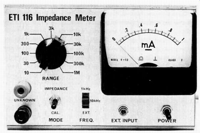
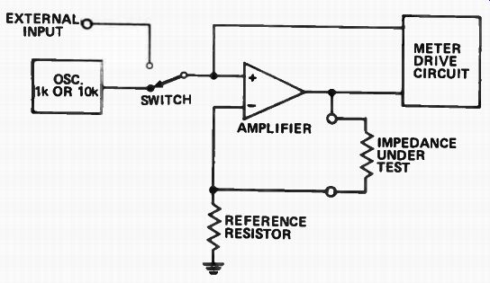
Fig. 1. Block diagram of the impedance meter snows that it consists of
an oscillator an amplifier and a meter circuit.
--------------
When measuring items which are connected to the mains earth either the item, or the meter, must have the earth removed.
------------------
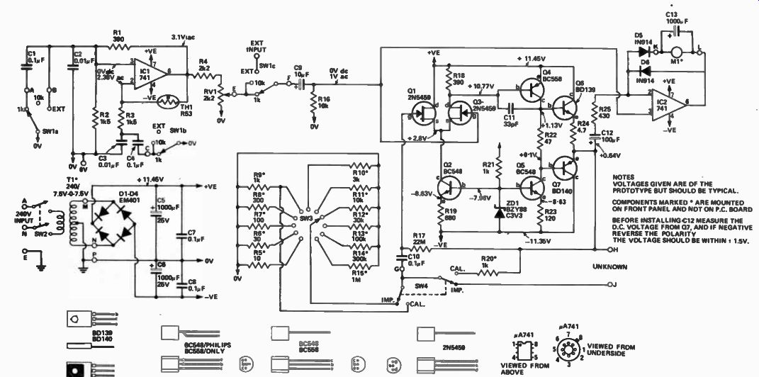
Fig. 2. Circuit diagram of the complete impedance meter.
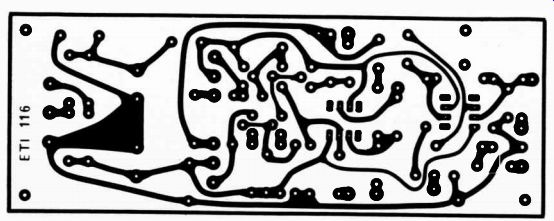
Fig. 3. Printed circuit board layout. Full size. 140 x 62 mm.
NOTES VOLTAGES GIVEN ARE OF THE PROTOTYPE BUT SHOULD BE TYPICAL COMPONENTS MARKED • ARE MOUNTED ON FRONT PANEL AND NOT ON PC. BOARD BEFORE INSTALLINGC12 MEASURE THE D.C. VOLTAGE FROM 07, AND IF NEGATIVE REVERSE THE POLARITY THE VOLTAGE SHOULD BE WITHIN. 1.5V.
--------------------
... measure the dc resistance as well as the impedance and calculate from the formula X = N/z2 - R 2 where X = reactance inductive or capacitive at the frequency used Z = magnitude of impedance (as measured on impedance meter)
R = dc resistance ( as measured by an ohmmeter).
MEASURING CAPACITANCE
The value of an unknown capacitor can easily be determined by measuring the impedance and then using the reactance chart. Or, it may be calculated from the formula:
1 C = 2 pi FX (with capacitors Xc= Zc) c If the 10 kHz frequency is used this may be simplified to C in microfarads = 16 (Z in ohms) and if 1 kHz CµF = ! 2. (Z in ohms) / ZC
Since the meter can resolve the range 1 ohm to 1 megohm this implies a capacitance range of 16 pF to 160µF. But as explained elsewhere stray capacitance limits the lowest capacitance that can be resolved to about 100pF.
MEASURING INDUCTANCE
To determine the value of an unknown inductance the impedance is gain measured and the value read off he reactance chart. Alternately the value may be calculated from:
L h x= igh L O zc Loils r L . N/ZL2 - R2 OM 03 coils)
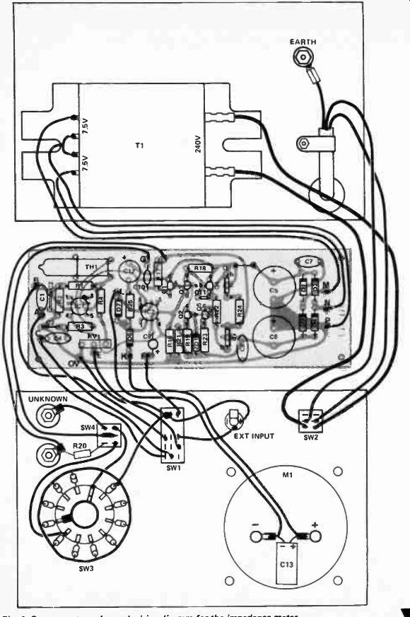
Fig. 4. Component overlay and wiring diagram for the impedance meter.
This is just one example of the many possible applications. In addition the meter may be used to measure component values by simply referring to a reactance chart or doing a simple calculation as detailed below.
Other applications include measuring the impedances of microphones, filters, transformers and amplifier inputs etc. All can be measured as easily as one would measure a resistor using an ohmmeter. Simply by connecting the device to the input terminals of the meter and making the measurement as detailed in the " How To Use" section.
In most practical applications we require to know the magnitude of the impedance - we do not care whether the device is predominantly inductive )r capacitive.
On the rare occasions that we do require to know reactance we can ...
----------------
HOW IT WORKS
Eh-116
The basic format of the impedance meter may be seen from the block diagram Fig.1. Firstly, we have an oscillator which may be switched to provide either 1 kHz or 10 kHz. Then we have a differential amplifier with a high input impedance, and lastly a meter drive circuit.
Either output of the oscillator, or an external frequency, as required, is passed to the non-inverting input of the amplifier. The amplifier gain is set by the ratio of the unknown impedance, Z, to the reference resistance, R. Due to feedback, the voltage across R is always equal to the input voltage and, as the amplifier requires no input current, the current through R must also flow through the unknown impedance, Z. The voltage across Z is therefore proportional to its impedance.
The meter circuit measures the output voltage by using the input voltage as a reference. Since the input voltage is equal to the voltage across R, we are effectively measuring the voltage across Z. Refer now to the main circuit diagram Fig.2. The oscillator is of the Wein bridge type and uses a 741 IC as the amplifier and an R53 thermistor as the stabilizing element. The circuit oscillates at the frequency where the impedance of C2 and C3 is equal to the resistance of R2 and R3 respectively. Therefore, to change frequency, we simply change the values of C2 and C3. The output of the oscillator is attenuated by R4 and RV1 to approximately one volt.
The amplifier has a very high input impedance, can supply about 200 mA into a load, has an open-loop gain of 50 dB and can work into any load including a short circuit (unity An integrated circuit operational amplifier having the above characteristics (at reasonable cost) is not available, hence, a discrete seven transistor design was used. To obtain the high impedance input a pair of FETs, QI and Q3, used as a differential pair, operate with a constant current (4 mA) supplied by Q2. Transistor Q4 is supplied with a constant current of 22 mA by Q5, and Q4, in conjunction with the input pair, supplies the necessary overall gain. Transistors Q6 and Q7 buffer the output of Q4 and Q5 to provide the necessary current drive.
The dc bias for the amplifier is provided by R17 such that an output voltage within ± - 1.5 volts of zero is always obtained.
The meter drive circuitry consists of a 741 IC with a meter, and half wave rectifier in series, connected in the feedback path. A second diode is used to prevent the IC being saturated on the opposite-polarity swing.
The current in the meter is half the current through R25 and, since this is proportional to the difference between input and output voltages of the amplifier, is proportional to the voltage across the unknown impedance. The meter scale is linear and the IC effectively compensates for the diode drop. Capacitor C3 provides the smoothing necessary when working at frequencies less than 40 Hz.
As previously stated the gain of the amplifier is set by the ratio of the unknown impedance 'Z' and the reference resistor and is equal to:
Z + R (where Z may be complex)
The value of R is switch selectable from 10 ohms to 1 megohm in eleven ranges. In the calibrate mode a 1 k resistor, R20, is substituted for the unknown impedance and the 1-k range selected. This provides a gain of two and thus with one volt in we have two volts out and hence 1 volt into the meter circuitry.
Thus, on calibrate, the output of the oscillator (or the external oscillator level) should be adjusted by RV1 to obtain full scale deflection on the meter. The calibrate position should also be selected before changing the unknown impedance, as an open circuit may damage the meter by driving it well beyond full scale.
-------------------
It should be borne in mind that we are determining impedances by using audio frequencies in this instrument hence components such as RF coils may well have a different impedance at RF frequencies (due to skin effect etc) than they do at audio.
Additionally iron-cored coils have an inductance dependant upon the measuring frequency and upon dc current flowing. Hence such coils should be measured under conditions as close as possible to those when in circuit. Further the inductance value, as measured, will only be accurate on coils having a Q greater than 10.
If the dc resistance is greater than one tenth of the measured impedance the second formula should be used.
TURNS RATIO
To measure the turns ratio of an unknown transformer simply load the secondary with a value of resistance, R, which causes the impedance Zp (looking into the primary) to drop by 50% from the unloaded value. The turns ratio may then be calculated from N1 = ZP(N = number of turns)
N2 R
----------------
IMPEDANCE (OHMS) FOR IMPEDANCES GREATER THAN 10S2.
DIVIDE CAPACITANCE SCALE BY THE SCALING FACTOR AND MULTIPLY THE INDUCTANCE SCALES BY THIS FACTOR. e.g. A CAPACITOR WHOSE IMPEDANCE IS 6000 OHMS (SCALING FACTOR x 1000) AT 1 kHz VALUE IS 27/1000 = 0.027µF
*FIGURES IN BRACKETS ARE FOR 10 kHz
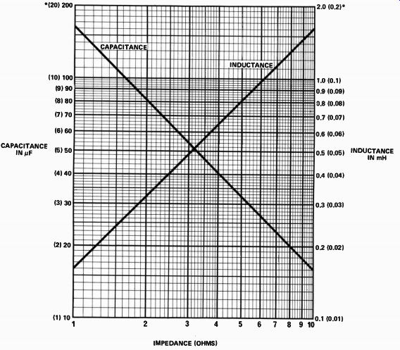
Fig. 5. Reactance chart for determining values of L or C from measured
impedance at 1 kHz (10 kHz in brackets).
---------------------
This calculation is based on the fact that an impedance in the secondary is transformed to an impedance in the primary that is proportional to the square of the turns ratio.
Many other applications can be devised for an impedance meter and the few mentioned here are indicative of the usefulness of such an instrument.
CONSTRUCTION
Any accepted construction method may be used but the use of a printed circuit board will greatly simplify the procedure.
Components should be assembled onto the printed circuit board, with the aid of the component overlay Fig 4, making sure that all polarized components are orientated correctly.
Capacitor C12 should not be fitted initially as the required polarity must be determined as follows.
Temporarily connect the transformer to the otherwise completed board and switch on the power. Measure the voltage from the amplifier at point H. This should be within ± 1.5 volts of zero. If this voltage is negative reverse the polarity of C12 to that shown on the overlay. If the voltage is positive use the polarity shown. This variation of voltage at point H is due to differences in the FET transistors 01 and 03.
Attach wires to all output connections of the printed circuit board allowing sufficient length to terminate them in their respective positions. Install the board in position using 12 mm long spacers and countersunk screws. Countersunk screws are necessary as they will be covered by the lid of the box. Install the power transformer and power lead, on the rear panel, together with the power-cord clamp and earth lug.
Mount the slide switch to the front panel using countersunk screws.
Resistors R5 to R14 should be mounted on the rotary switch SW3 before mounting it on the front panel.
If the 30, 300, 3k etc resistors are not available they may be replaced by a parallel combination; eg 30 ohms is obtained from 33 ohm and 330 ohms in parallel and 3 k from 3.3 k and 33 k in parallel.
The rest of the front panel components, except the meter, ( for ease of wiring) should now be mounted together with the escutcheon. The wiring can now be completed and the meter installed and connected.
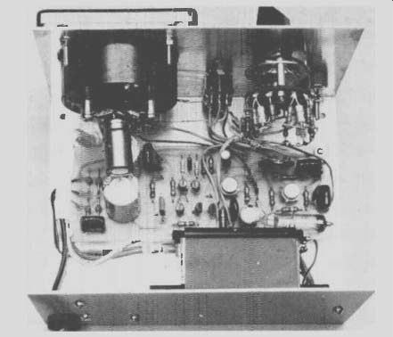
Fig. 4-2. Internal view of the meter shows how the board and other components
are positioned.
USING THE METER
The meter should be used in the following manner:-
1. Switch the cal/impedance switch to cal.
2. Switch on power.
3. Select the required test frequency. The meter should read full scale, if not, adjust RV1.
4. If an external oscillator is used set the frequency and adjust oscillator output level to obtain fall scale reading.
5. Connect the impedance to be measured.
6. Select the one megohm range.
7. Switch the cal/impedance switch to impedance.
8. Reduce the range, if necessary, to obtain a readable deflection. This reading s the required impedance; eg 0.6 on the 10 k range is an impedance of 6k.
9. If desired the external frequency may be varied to obtain a plot of impedance versus frequency.
10. Switch back to ' Cal' before removing the impedance being measured.
--------------
TABLE 1
Error Resistance Capacitor
Capacitor
(R2/R3) (C1,C4) (C2,C3)
1% 150k 0.001µF 100 pF 2% 68k 0.0022µF 220 pF 3% 47k 0.0033µF 330 pF 4% 39k 0.0039µF 390 pF 5% 27k 0.0056µF 560 pF 6% 22k 0.0068µF 680 pF 7% 18k 0.00824F 820 pF 8% 18k 0.0082µF 820 pF 9% 15k 0.01uF 1000 pF 10% 13k 0.01µF 1000 pF
--------------
PARTS LIST - ETI 116
R24 R5 R6 R22 R7 R23 R8 R1,18 R25 R19 Resistor
•9 R9,20,21 " R2,3 R4 R10 R11,16 R12 R13 R14 R15 R17
•e
4.7 ohm I/2W 5% 10 30 PP 47 IP •• 100 tt 1 P et 120 300 390 430 680 1k Ik5 2k2 3k 10k 30k 100k 300k IM 22M RVI Potentiometer 2k2 Trim type THI Thermistor type R53 C 1 I Capacitor C2,3 C1,4,7 " C8,10 " C9 C12 C13 C5,6 tt Q1,3
Transistor Q2,5 Q4 Q6 Q7 33pF ceramic
0.01 uF polyester
0.1
0.1uF 10 uF 16V electrolytic 100uF 6.3V electrolytic 1000uF 6.3V electrolytic 1000uF 25V electrolytic 2N5459 or similar BC548 BC558 BD137, BD139 BD138, BD 140 IC1, 2 Integrated Circuit 11.4741C mini dip or TO5 Dl-D4
Diodes
05, 6 " ZD1
Zener Diode EM401 or similar IN914 BZY88 C3V3 or similar T1 Transformer 240V/7.5-0-7.5V 1-A PL 1.5-18/20VA, PL 15/20VA M1 Meter 0-1 ma F5D. 75 x 65 mm SW1 Switch SW2 SW3 SW4 19 three pole three position slide switch DPDT 240V toggle switch one pole eleven position rotary switch CrPOT toggle switch PC board ETI-116, Metal box Dick Smith type LMB 564, Front panel, small phone socket, pointer knob, 3 core flex and plug, rubber grommet and cable clamp, four 12 mm long spacers two terminals, nuts & bolts etc.
----------------
FREQUENCY CALIBRATION
The frequency should be within 10% of nominal if specified components are used. However, if a frequency meter is available the network can be trimmed to give the correct readings.
Measure both the 1 kHz and the 10 kHz and calculate the percentage errors. If either or both are low in frequency the resistors R2 and R3 can be paralleled with additional resistors to increase the frequency. Since this will affect both ranges choose the one with the greatest error. Table 1 gives the correct resistance to use.
Re-measure the frequencies. One frequency should now be right and the other high. The capacitors C1 and C4 or C2 and C3 can be paralleled by the appropriate capacitors as selected from Table 1.
LIMITATIONS
Due to stray capacitance, (about 15 pF) associated with the front panel terminals and the switches, the 1 megohm range is useful only up to about 4 kHz. The 300 k range is useful to about 10 kHz.
When measuring series LCR networks (where the impedance rises greatly off resonance) it is usually necessary to parallel a resistor across the network to stabilize it. Once at resonance, the resistor may be removed for the actual impedance measurement. The frequency can now be altered provided that the meter is not allowed to go off scale. The resistor used should be not more than 10 times the value of the network impedance at resonance.
ETI 116
Impedance Meter
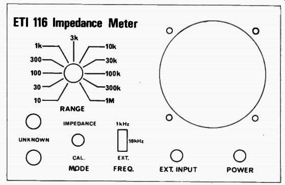
Fig. 6. Layout of front panel. Full size is 152 x 98 mm.
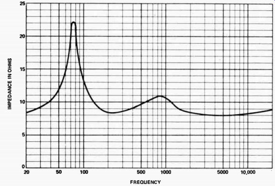
Fig. 7. Impedance-versus-frequency plot for a two-way speaker box. Note
the combined speaker/box resonance is 75 Hz. The crossover frequency was
2 kHz. A plot such as this would be extremely difficult to generate using
a conventional LCR bridge, but is very simply done using the ETI 116 impedance
meter.
------------
CIRCUIT DIAGRAM MARKINGS ELECTRONICS
Today International is adopting British Standard BS1852: 1967 for marking component values on circuit diagrams.
The values of components are given by figures but the decimal point is replaced by a multiplier symbol in accordance with a table of standard prefixes. This procedure greatly reduces the possibility of errors.
Examples
4k7 equals 4.7 k ohm 47 k 47 k ohm 1 M 5 " 1.5M ohm 4n7 " 4.7 nF 6p8 " 6.8 pF
Where a multiplier is not needed, the symbol ' R' is inserted to signify ohms.
Example 4R7 equals 4.7 ohms Note also that capacitors that were formerly specified as decimal fractions of microfarads ( 10^6F) are now expressed in nanofarads ( 10^-9 F). Example 0.01µF = 10 nF
Abbreviation
Read as: Multiplies unit by: G h da d a tera giga mega kilo hecto deka deci centi milli micro nano pico femto atto 10^12 tog 10^6 10 3 102 10 10 -1 10-2 10-8 10-6 10 -8 10' 12 10 -18 10 18 Standard prefixes . Multiplier symbols above 1000 are written with capital (upper case) letters, multipliers below 1000 do not use capitals ( i.e. they are in lower case). When spelled out in full, all multipliers start with a lower case letter ( except when it is the first letter in a sentence). Thus:
- 10 MW = 10 megawatts
- 10 mW = 10 milliwatts