Inexpensive unit for converging COLOR TV set.
THE COLOR television picture is created in the receiver picture tube by three separate electron guns -- one each for red, green and blue. As these guns cannot be in the same physical position they need to be converged into one spot on the screen.
The process of converging at the center of the screen is called static convergence and is performed by magnets on the yoke assembly.
However, the screen of the picture tube is not everywhere coincident with the deflection plane and this causes errors when the beam is deflected away from centre. These deflection errors are corrected electronically by 12 or more controls and the process is known as dynamic convergence.
An important part of the process is the use of a crosshatch generator to provide horizontal and vertical lines on the screen. Using the generator, the convergence errors are immediately apparent and the controls on the set are usually labeled with the effect each has on a crosshatch pattern.
In addition to setting up convergence the generator pattern may also be used to set up horizontal and vertical linearity and to orientate the deflection yoke coils on both black and white and COLOR sets.
Most of the inexpensive pattern generators, which are currently available, produce a video waveform, which must be injected into the correct place in the TV, and require a synchronizing signal from the TV set.
Such generators are thus fiddly things to use.
The ETI 704 generator produces a combined horizontal and vertical-sync waveform and this, together with the crosshatch video, is modulated onto a carrier frequency operating in VHF channel 6 ( 175.25 to 180.75 MHz). Thus to use the generator one simply attaches it to the antenna terminals and selects channel 6.
CONSTRUCTION
Coil L1 should be constructed from 24 gauge B&S enameled copper wire by winding 6 turns, close spaced, around a former, such as a knitting needle, so that the finished outside diameter of the coil is about 5 mm.
Coil L2 is constructed by winding 4 turns of 24 gauge B&S enameled copper onto a miniature Neosid former which is fitted with a VHF slug and an aluminum can. Fit links to the board in accordance with Fig. 2 and then the above coils and other components can be assembled to the printed circuit board with the aid of the component overlay. Take particular care with the orientation of ICs and other polarized components.
Assemble the CMOS devices to the board last of all and handle them as little as possible. Avoid touching the pins.
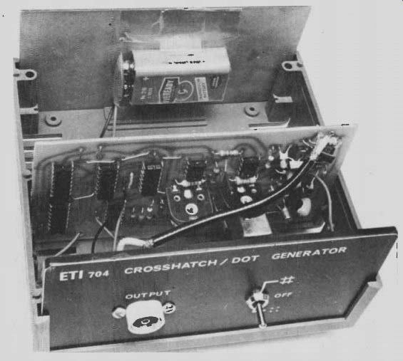
Assemble the output socket and switch to the front panel and connect the output of the module to the socket by means of a short length of 75 ohm coaxial cable. The connections to the switch and battery may then be made with ordinary hookup wire.
SETTING UP
Connect the unit to the antenna terminals of a television receiver and select Channel 6. Adjust the coil L2 to obtain the strongest signal on the screen. (This may be totally out of sync at this stage.) Now adjust RV2 as you would a normal horizontal sync control to obtain vertical lines and then adjust RV1 for vertical sync. Then readjust L2 for clearest picture and make small adjustments to RV2 and RV1 to obtain the most stable crosshatch.
Finally adjust brightness and contrast of the set to obtain white lines on a black background. These adjustments need only be made on initial set up and henceforth the generator is simply attached to the antenna terminals and switched on.
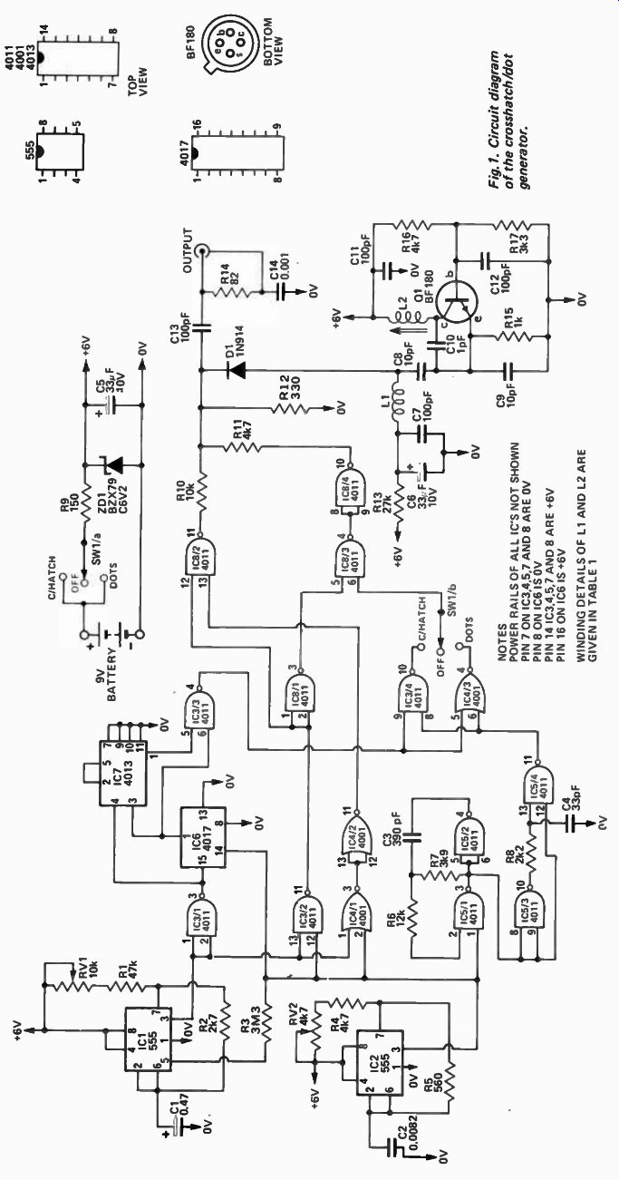
Fig. 1
HOW IT WORKS - ETI 704
Two 555 timers, IC1 and IC2, are used as the frame and line sync pulse generators respectively. Integrated circuit IC1 generates one millisecond wide pulses at 20 millisecond intervals (50 Hz) and IC2 generates five microsecond wide pulses at 64 microsecond intervals ( 15625 Hz). Light synchronization of ICI to IC2 is achieved by means of R3. Thus both oscillators have to be close to the correct frequency before locking will occur.
Gates IC3/2, IC4/1, IC4/2 and IC8/2 form an exclusive-OR function on these two sync-pulse trains to produce a combined sync-pulse train at the output of IC8/2.
At the end of each line-sync pulse an oscillator, formed by IC5/1 and 2 is gated on, and produces a train of pulses at approximately 240 kHz.
The leading edge of each of these pulses triggers monostable IC5/3 and IC5/4 such that a 40 nanosecond wide pulse is generated. Thus approximately 14 40 nanosecond wide pulses are generated between successive line sync pulses. These pulses produce the vertical lines of the crosshatch.
At the end of each frame sync pulse decade counter IC6 is enabled. This is a CMOS Johnson decade counter which provides an output at pin 1 every tenth line sync pulse commencing from the 5th pulse after the counter is enabled. This output is divided by two by IC7 and the output of IC3/3 is therefore low for the duration of every twentieth line period. This output is the horizontal lines of the crosshatch.
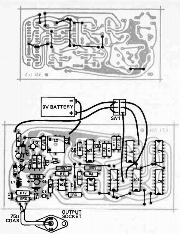
Fig. 3. Component overlay.
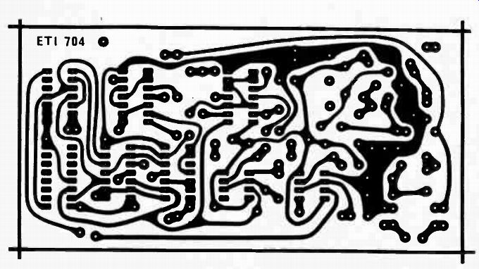
Fig. 4. Printed circuit board layout.
-----------
PARTS LIST - ETI-704
Resistor
RI 47k R2 " 2k7 R3 " 3M3 R4 " 4k7 R5 " 560 R6 12k R7 " 3k9 R8 " 2k2 R9 " 150 R10 " 10k R11 " 4k7 R12 " 330 R13 " 27k R14 " 82 R15 " lk R16 " 4k7 R17 " 3k3 1 / 2 W 5% YU OF 111 Oli VP RVI
Potentiometer 10k Trim type RV2 4k7 "
C1
Capacitor 0.47pF TAG Tantalum C2 " 0.0082 uF Styroseal C3 " 390pF ceramic C4 33pF C5 " 331,1F 10V electro C6 " 33 uF 10V C7 " 100pF ceramic C8 " 10pF ceramic CO " 10pf ceramic C10 " 1pF ceramic C11" 100pF ceramic C12 " 100pF ceramic C13 " 100 pF C14 " 0.001 uF ZD1 Zener Diode BZX79C6V2 D1 Diode IN914 Q1 Transistor BF180 IC1,2 Integrated Circuit NE555 IC3,5,8 " 4011 ( CMOS) IC4 " " 4001 (CMOS) IC6 " " 4017 ( CMOS) IC7 " " 4013 (CMOS) Li Inductor see text L2 Inductor see text PC Board ETI 704 DPDT with centre off toggle switch 75ohm socket 9V battery and connector Box PC1 or similar ( A&R sonar).
-------------
The vertical and horizontal crosshatch signals are NANDed and NORed by IC3/4 and IC4/3 respectively to provide either crosshatch or dots as selected by SW1/b. These outputs are inhibited during the line and frame sync periods via IC3/2, IC8/1 and IC8/3.
The output from IC8/4 is thus the composite crosshatch video signal.
The composite sync from IC8/2 and the composite video from IC8/4 are summed into R12 by R10 and R11 and form a combined sync and video waveform which modulates the RF from oscillator Q1 via diode D1.
Transistor Q1 and its associated components form an oscillator which runs at around 180 MHz. The output from the generator is therefore a modulated RF signal at channel 6 frequency which is adjustable by tuning coil L2.
The unit is powered from a 9 volt battery which is only on when dots or crosshatch are selected. The 9 volts is regulated down to 6 volts by means of R9 and zener diode ZD1.
--------------