A simple unit for servicing AM receivers.
AN RF SIGNAL generator is an invaluable instrument for AM radio servicing and alignment - it greatly simplifies alignment and allows each stage to be checked for gain and frequency response.
Three types of signal are required for these purposes. Firstly, we require an audio signal to check that part of the receiver from the volume control (after the detector) to the speaker.
Secondly, we need a modulated RF signal at 455 kHz (430 to 480 kHz available for non-standard receivers) for checking and aligning IF stages, and lastly, we need a modulated RF signal in the range 500 to 1600 kHz to check out the RF amplifier and converter.
In addition the level of the generator output should be adjustable so that AGC action may be checked out, and so that optimum levels may be chosen for servicing and gain checks. All the above requirements are met by the ETI 129 generator and, since only one of the available signals is used at any one time, e common level control is used for all these outputs.
In our generator the provision of IF frequencies from 430 to 480 kHz, as well as catering for non-standard receivers, allows receiver IF selectivity to be checked.
CONSTRUCTION
The prototype instrument was mounted in an aluminum box having external dimensions of 145 x 115 x 90 mm. Layout of the circuitry is important and for this reason the printed-circuit board layout provided should definitely be used. Take care when assembling components to the printed-circuit board to correctly orientate capacitors C9, C11 and C15, transistors Q1 to Q4 and diode D1.
The variable capacitor is mounted onto the component side of the printed-circuit board but spaced from it by about 2 mm (an oversized nut may be used). The mounting of the board and variable capacitor assembly to the front panel and reduction-drive assembly may best be understood by referring to Fig. 3. Note that the board is mounted by four standoffs and that rubber grommets are used to allow the board to move slightly -- for this reason the screws should not be tightened too much. This method is used to avoid the expense of using a flexible drive to the variable capacitor.
The six-to-one slow-motion drive is mounted to the front panel by two 15 mm long bolts. The drive is spaced back from the front panel by 4 mm long spacers.
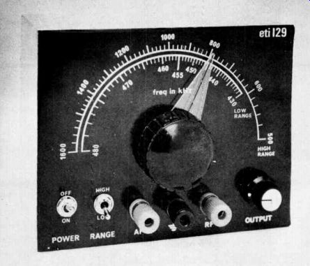
The remaining controls are mounted straight onto the front panel as shown in the photograph.
Scotchcal front panels, ready to stick on are available from Electronics Today at $4.00 each.
Send stamped addressed envelope - size at least 150 x 120 mm. Address to Scotchcal Offer, Electronics Today, 15 Boundary Street, Rushcutters Bay, NSW 2011.

--------------- Printed-circuit board layout.
Full size 129 x 80 mm.
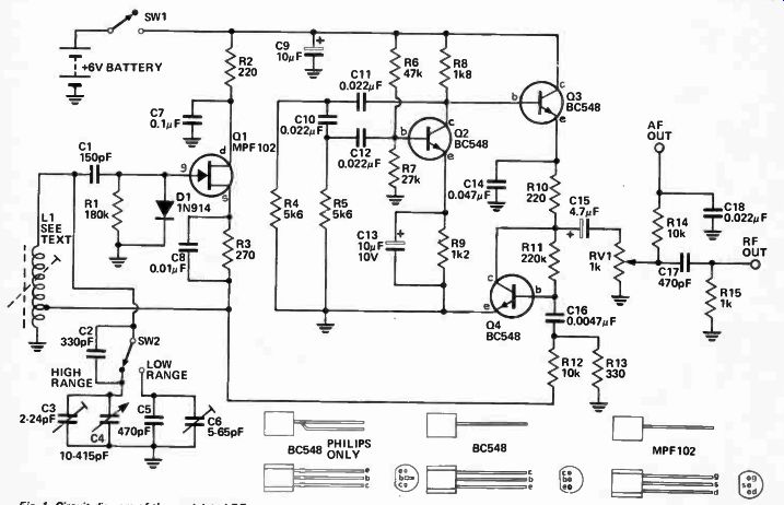
Fig. 1. Circuit diagram of the modulated RF generator.
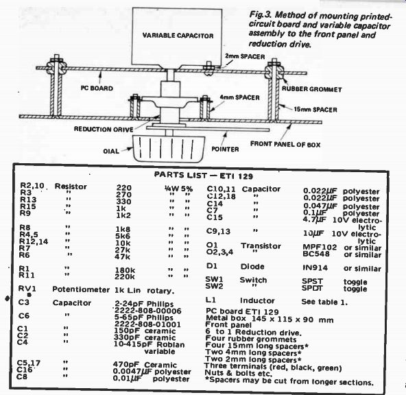
Fig.3. Method of mounting printed circuit board and variable capacitor
assembly to the front panel and re-duct on drive.
----------------
PARTS LIST -- ETI 129
Philips 2222-808-00006 5-65pF
Philips 2222-808-01001 150pF ceramic 330pF ceramic 10-415pF
Roblan variable 470pF
Ceramic
0.0047uF polyester
0.01 uF polyester
C10,11 C12.18 C14 C7 C15 C9,13
01
02,3,4 D1 SWI SW2
Capacitor
Transistor MPF102 BC548
Diode IN914 or similar
Switch SPST toggle SPOT toggle
0.022uF polyester
0.022 uF polyester
0.047uF polyester
0.1 uF polyester 4.7 uF 10V electrolytic 10 uF 10V electrolytic or similar or similar
L1 Inductor See table 1.
PC board ETI 129 Metal box 145 x 115 x 90 mm Front panel 6 to 1 Reduction drive.
Four rubber grommets Four 15mm long spacers* Two 4mm long spacers* Two 2mm long spacers* Three terminals ( red, black, green)
Nuts & bolts etc.
Spacers may be cut from longer sections.
-----------------
CALIBRATION
High Range. Using a conventional AM receiver tune to a station at the top end of the frequency band. Set the pointer of the RF generator to indicate the frequency of the station being received and couple the generator to the receiver.. Adjust capacitor C3 until the signal from the generator can be heard interfering with the station. This will take the form of a whistle which, as C3 is tuned, wiil go from a high frequency to a low frequency and then back to a high frequency again. The correct tuning point is where the frequency is at its lowest, i.e. in the middle. The level of the generator signal may have to be increased to obtain the correct point with accuracy. This procedure is called 'zero beating'. Now tune the receiver to a station at the low end of the band. Again set the pointer of the RF generator to the frequency at which the station operates and adjust the slug of L1 for zero beat in the same manner as for the high end.
Repeat the procedure for both the high and low ends of the band until there is no change at either end.
Low Range. The low range should be calibrated after the high range calibration has been completed.
First set C6 to mid position. Then tune in a station on a broadcast receiver that lies somewhere between either 860 and 960 kHz or 1290 and 1440 kHz. These two bands are twice and three times the generator IF band respectively. That is, we are working on the second or third harmonic of the generator respectively. Divide the actual frequency of the tuned-in station by two (for stations between 860 kHz and 960 kHz) or by three for stations between 1290 and 1440 kHz.
Now set the pointer on the RF generator to this frequency. Adjust the capacitor C6 for zero beat as detailed for the high range.
Refer to any standard textbook for alignment procedure for AM receivers.
RANGE
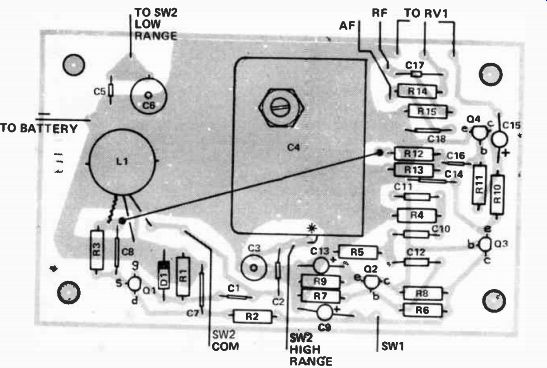
Fig. 2. Component overlay for the RF generator. Note the wire
link between R12 and C8 which should be installed before fitting C4.
Also note the connection from C4 to the board where shown by the asterisk.
HOW IT WORKS - ETI 129
The circuit may be sub-divided into three basic sections.
These are: RF or carrier oscillator.
b) AF or modulation oscillator.
c) Modulator and buffer amplifier.
a) Transistor Q1 is connected as an Hartley oscillator.
The positive feedback necessary for oscillation is provided from the source terminal of Q1 back to the gate via coil Li. The frequency of oscillation is determined by coil LI in conjunction with capacitors C2 through C6.
Two ranges are provided, 500 kHz to 1600 kHz with L1, C3 and C4; and 430 to 480 kHz with L1, C2, C5 and C6. Diode D1 is used to develop a negative bias across R1 which thus limits the level of oscillation, and hence prevents damage to the gate of Q1.
b) Transistor Q3 is connected as a phase-shift oscillator. The network C10,C11, C12, and R3, R4 provides about 180° phase shift of the signal at the collector of Q3, and the feedback to the base of Q3 is therefore positive - causing oscillation. The frequency of oscillation is about 600 Hz.
c) Transistor Q4 is a class 'A' amplifier which is biased by the half-supply method ( R10 and R11) the operating supply being obtained from emitter-follower ,Q3. The output of Q3 is the sine-wave from the phase-shift oscillator. Because of R11 any change at the junction of Q3 and R10 causes a corresponding change in the emitter current of Q4.
The emitter current of Q4 therefore varies at the rate of 600 Hz. The emitter resistance of a transistor depends on the emitter current of that transistor and the gain depends on the ratio of the collector load, R10 to the emitter resistance. Since the emitter resistance is varying at 600 Hz, the gain of the transistor will also be varying at 600 Hz and so the RF signal fed to the base of Q4 from Q1 by C16 is modulated by the audio signal.
The signal across R10 is fed to RV1 by C15 and this signal consists of two components - the modulated RF and the audio tone.
After attenuation by RV1 the signals are separated by high and low pass filters to the AF and RF outlets.
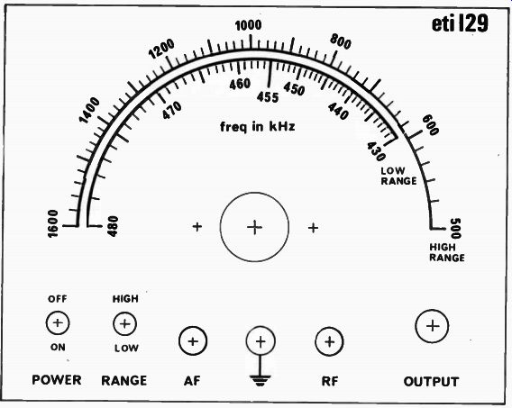
Fig. 4. Front panel artwork. Full size 148 x 116 mm.
COUPLING TO RECEIVER
Method 1. To ferrite rod coil. Connect one end of a length of ordinary hook-up wire to the RF OUT jack and then wrap about two turns of the other end of the wire around and over the aerial coil on the ferrite rod.
Method 2. To an IF amplifier. Connect a wire to the RF OUT jack and to its other end connect a 0.001 capacitor and a 1 k resistor in series. To inject the signal into the IF stage just connect the free end of the resistor to the base of the IF stage transistor.
In both the above methods if insufficient signal level is available an earth connection may also have to be made between the generator and the receiver.
Method 3. Audio testing. Use a length of wire as before but with a series capacitor of about 0.47µF. Note that an earth connection will definitely be required in this case. Once again the best place to inject a signal is straight into the base of the transistor. • Internal view of the generator.
----------------- TABLE 1
L1 CORE 20 turns 0.5 mm enameled copper wire tapped at four turns from grounded end.
Philip pot core P18 series, material 3B7 or 3H1, e = 220. Part No 4322- 022
- 24280 or 4322 - 022 - 24080
FORMER 4322 - 021 - 30270 ADJUSTOR 4322 - 021 - 31080 CLIP 4307 - 021 - 20000 One each of core, former, adjustor and clip required to assemble one complete coil.
--------------
--------------