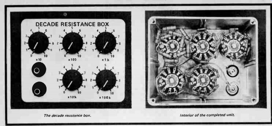
A versatile and accurate variable resistance unit for experimenters.
A DECADE resistance box is an extra ordinarily useful device -- enabling the user to select precisely the resistor value needed when that breadboard mock-up doesn't quite match the theoretical calculations: there being nothing more time consuming than the 'unsolder and try another' technique.
Another use for a decade box is as a precision variable resistor in experimental measurements -- and to meet this requirement we have provided ten-ohm resolution and have specified 2% accuracy resistors. These resistors are available at reasonable cost -- you could of course go to 1% resistors but such accuracy is rarely needed for most applications.
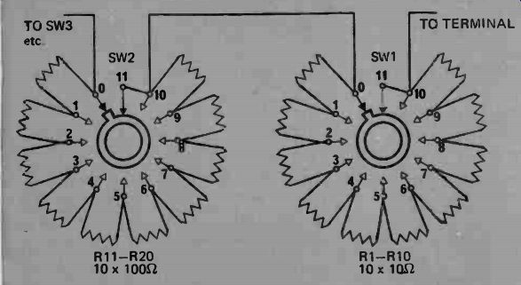
Fig. 1. The method of interconnecting the switches.
------------
PARTS LIST
R1 - R10
Resistor 10-ohm 2% 1/2 watt Philips type MR30 or equivalent.
R11 -- R20
Resistor 100 ohm 2% 1 / 2 watt Philips type MR30 or equivalent R21 - R30
Resistor 10002 2% 1 / 2 watt Philips type MR30 in equivalent R31 - R40
Resistor 10 k-ohm 2% V; watt Philips type MR30 or equivalent
R41 - R50 Resistor 100kohn 2% 1/2 watt Philips type MR30 or equivalent
SW1 - SW5
Wafer switch, single pole, 11 position OAK type F or similar.
diecast box 4 3 / 4" x 3 3 / 4' x 2", ITT type
043B00 or similar.
2 binding post terminals and 5 knobs.
-----------------
CONSTRUCTION
Assemble the resistors to the switches as shown in the photograph, R1- R10 to SW1, R11-20 to SW2 and so on to SW5.
Fit the switches to the metal box and ensure that the resistors are clear of the metal box sides. If there is insufficient clearance a piece of manila-folder cardboard will provide the necessary insulation.
Connect all the switches in series, as shown in Fig.1, and then connect the wiper of SW1 to one of the input terminals with one single strand from a piece of flexible hook-up wire. This switch contacts from damage due to will act as a fuse and protect the shorts. Finally connect pin "0" of SW5 to the other terminal.
In our prototype we disassembled the switches and filed away the stops thus allowing continuous rotation in either direction. Be very careful, if you decide to do this, not to damage the switch. Remove the wafer assembly taking care not to apply pressure to the rotating wiper section. Remove the circlip retaining the shaft and withdraw the shaft/clicker plate assembly. The stop may then be removed with a file and the switch reassembled.
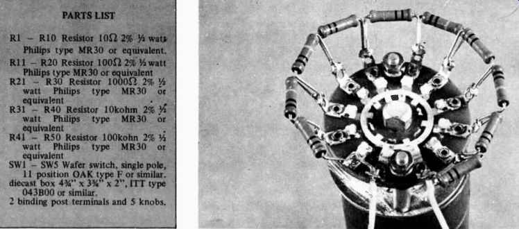
Fig. 2 The resistors are mounted to the switches as shown.
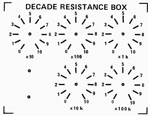
Fig. 3. Front panel overlay (full size).

Fig. 4. Drilling details for the diecast box.
--------------------