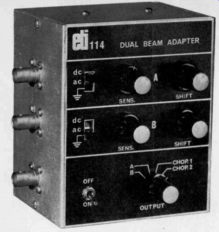
Simple unit converts single beam CRO to dual beam operation.
THE oscilloscope, next to the multimeter, is perhaps the most useful test instrument. Indeed, for any serious experimental work an oscilloscope is indispensable.
Unfortunately they are expensive beasts, and whilst an experimenter may well afford a simple, low-frequency single-beam type, a dual- beam version ( at $300 or more) is usually beyond his means.
Nevertheless a dual- beam facility is most convenient, for it allows comparison of two different signals, for wave-shape or timing, and makes obvious, differences which otherwise would not be discernable.
The simple dual-beam adaptor described here, whilst not providing all the capabilities of an expensive dual- beam CRO, will however, cover most experimenter's requirements.
It is a low cost unit which allows two inputs of similar amplitude to be displayed simultaneously on separate traces. Frequency response of the unit is sufficient to allow observation of signals up to about 1 MHz.
CONSTRUCTION
Most of the components are mounted on a printed circuit board.
However, if desired matrix or veroboard may be used.
Be careful to orientate the polarised components correctly, as shown on the component overlay. Wiring to the sockets and switches should be as short as possible. Note that C3 and C4 are mounted on the input switches and C5 is mounted on the output socket.
Our prototype was mounted in a small aluminum minibox as illustrated. As individual requirements will vary, details of front panel layout and metalwork only are supplied.
USING THE ADAPTOR
Connect the output of the adaptor to the input of the CRO. The two adaptor inputs now become A and B trace inputs to the CRO. A triggering signal should be applied direct to the trigger input of the CRO as otherwise the CRO will tend to synchronize to the chop frequency and not to either input signal.
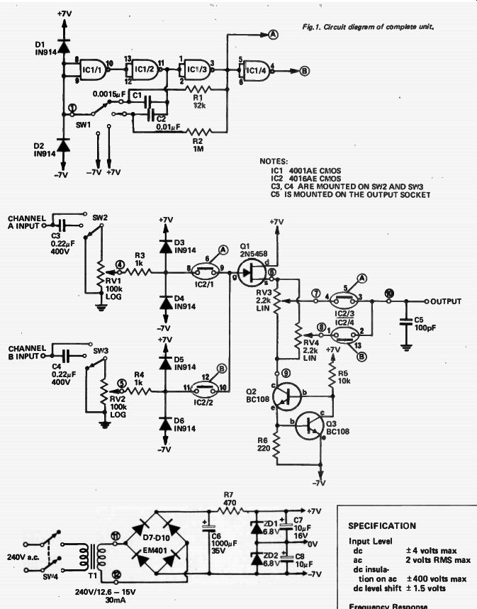
Fig. 1. Circuit diagram of complete unit.
------ NOTES:
IC1 4001AE CMOS
IC2 4016AE CMOS
C3, C4 ARE MOUNTED ON SIN2 AND W13
C5 IS MOUNTED ON THE OUTPUT SOCKET
----------
It is preferable that the two input signals have approximately the same amplitude as there is no input amplifier or range selection provided on the adaptor. However there is an attenuator provided on each input so that some adjustment may be made.
If only one input is to be applied it is best to switch to that input only thus eliminating the second trace and any cross talk which may occur due to the high input impedances.
Two chopping frequencies are used, having widely different frequencies, so that if the input signal is a harmonic of the chopping frequency, ( see Fig. 4) choosing the other chop mode will prevent the chop frequency being visible.
---------------
SPECIFICATION
Input Level dc ac dc insulation on ac dc level shift 1 - 1.5 volts
± 4 volts max 2 volts RMS max
± 400 volts max
Frequency Response
- 3dB point > 1 MHz
Chopping Frequencies A 60 Hz 35 kHz
Input Impedance 100 k ohm
------------------------
Normally CHOP 1 would be used for high frequency inputs, and CHOP 2 for low frequency inputs. An ALTERNATE mode has not been included ( entails obtaining an output from the CRO of unknown level and availability) as the CHOP 1 mode is similar and almost as effective.
By means of the two shift controls traces A and B may be separated by up to ± 1.5 volts.
-------------- HOW IT WORKS - ETI 114
Switches SW2 and SW3 select de or ac coupling, or input shorted, for channel A and channel B inputs respectively. The signals are applied to the sensitivity potentiometers RV1 and RV2 and then passed to IC2/1 and IC2/2 which select one of the signals as an input to source follower Q1.
Transistor Q1 is supplied with a constant current ( approximately 2.7 mA) by transistors Q2 and Q3.
Hence, there is about 3 volts across RV3 and RV4, and this is unaffected by changes in input signal level.
These potentiometers therefore provide a level-shift facility. When channel A is selected by IC2/1, IC2/3 selects RV3, and when channel B is selected by IC2/2, IC2/4 selects RV4.
Thus as each signal has an independent level shift the two traces may be separated when chopped.
The CMOS gates of IC2 are driven by the outputs, A and B, the circuitry associated with IC1. The drive circuit mode of operation is selected by SW1, a four position switch, such that channel A only, channel B only, A and B chopped at 60 Hz or, A and B chopped at 35 kHz may be selected. The operation is as follows.
Integrated circuit IC1 forms a multivibrator which can run at 60 Hz or 35 kHz, or be locked in A-high B-low, or A-low B-high output states.
For example, if SW1 selects - 7 volts, IC1 pin 10 will be at +7, IC1 pin 11 will be at - 7, IC1 pin 3 will be at +7 and IC1 pin 4 will be at - 7 volts. The CMOS switches of IC2 will be "on" if the control voltage is at +7 volts and "off" if the control voltage is at - 7 volts. Thus when - 7 volts is selected by SW1 , "A" will be at +7 volts, and IC2/1 and IC2/3 will select channel A. Similarly if +7 volts is selected by SW1, IC2/2 and IC2/4 will select channel B. If C2 and R2 are selected by SW1 the multivibrator will be free to run at 60 Hz and channels A and B will be alternately selected at this frequency. Similarly if C1 and R1 are selected, channels A and B will be alternately selected at 35 kHz.
The power supply is a simple full-wave bridge type which uses two Zeners to provide the +7 and - 7 volt supplies required.
------------------------
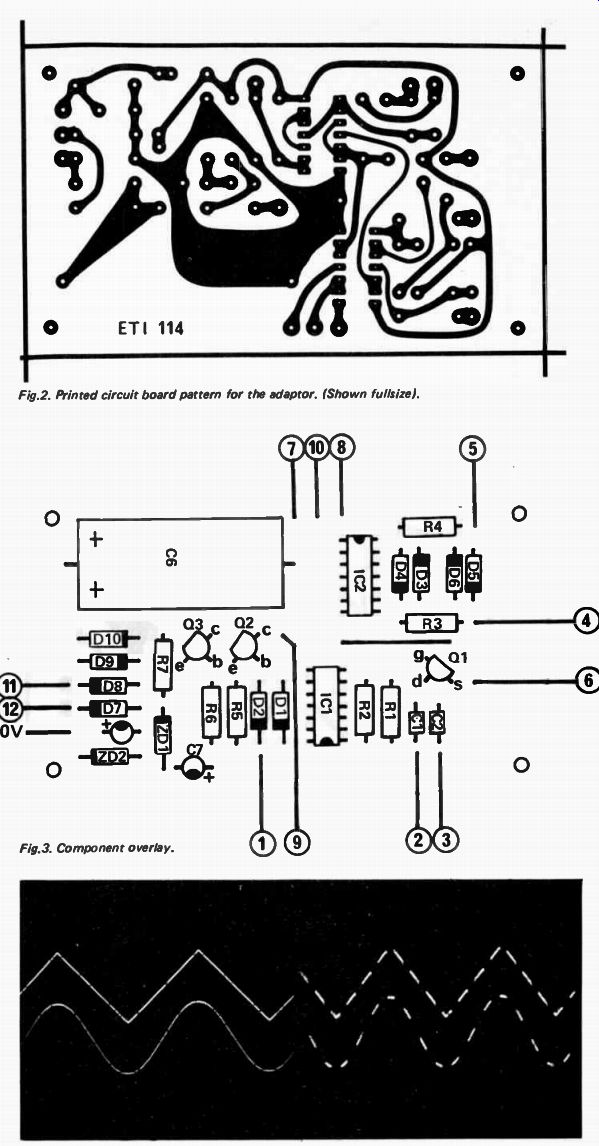
Fig. 2. Printed circuit board pattern for the adaptor. (Shown full-size).
Fig. 3. Component overlay.
Fig. 4a. Two signals, correctly displayed using the dual beam adaptor.
Fig.4b. Use of incorrect chopping frequency for a particular input signal (chop frequency a harmonic of signal) results in above effect.
To cure use other chop frequency.
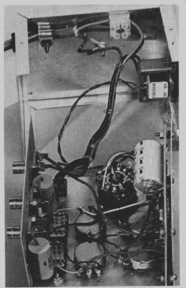
-------------- Layouts of components within the unit can be see from this and accompanying photographs.
DUAL BEAM ADAPTER
R6 R7 R3,4 R5 RI R2
PARTS LIST - ETI 114
Resistor or
09 220 1 / 2W 5% 470 1 / 2W 5% 1k 1 / 2W 5% 10k I/2W 5% 12k 1 / 2 W 5% IM 1 / 2W 5% RV1,2
Potentiometer 100k log rotary RV3,4
Potentiometer 2.2k lin rotary C5
Capacitor agn ceramic ester
C1
C2 0.01F polyester
C3,4 .. 0.22 uF 400V poly.
C7,8 " 10 16V electrolytic C6 nowe 35V D1-D6 Diode I N914 or similar D7-D10 " EM401 or similar ZD1,ZD2
Zener Diode BZY88C6V8 or similar
Q1
Transistor 2N 5458 Q2,Q3 " SC108, BC548 or similar
IC1 Integrated circuit 4001AE CMOS
IC2 Integrated circuit
4016AE CMOS
T1 transformer 12.6V - 15V @ 300 ma PF285I, PF3786, A& R7577 etc.
PC Board ETI 114
SW1 switch one pole 4 position rotary
SW2,3 switch 3- position slide switch
SW4 switch 2-pole on-off toggle 240V rated.
Metal Box 130mm x 105 mm x 80 mm 3 sockets to suit
CRO leads Knobs for front panel.
--------------------