Speakers may be A- B tested using this simple modification to our tone-burst generator.
WHEN evaluating speaker systems in A-B listening tests, the first few seconds of listening convey the truest impression of sound quality. Listening for longer than a few seconds not only fails to give further information, but may well give a false indication. For this reason it is usual to switch rapidly between the reference speaker and the speaker under test. This is generally done by using the amplifier's A/B speaker selector switch, or by wiring a change-over relay in the speaker wiring.
---------------------- HOW IT WORKS - ETI 124 AB
As this unit is based on the operation of the tone-burst generator ETI 124 described here, that article should be thoroughly read first. Only the changes necessary to that unit are detailed in this article. A-B switch would be a little simpler if designed specifically for that purpose, the modifications required to the tone-burst generator are so simple that we thought it not worth while to design a special circuit.
To make the generator act as an A-B switch it is necessary to disable the existing mode switch. We do this by plugging in an external control switch, SW6, via a stereo phone socket. The phone socket has two change-over contacts fitted which are used to disconnect the plus and minus six volts supplies from SW3 when the jack is inserted. One of the phono contacts also disconnects the plus six volts from the common of the socket when the jack is removed.
As the common of the socket is required to be at plus six volts the phono socket must be insulated from the front panel which is at 0 volts.
The control switch, SW6, effectively shorts either R4 or R5 thus stopping the pulses from C2 or C3 triggering the flip-flop. When the switch is actuated there is a delay until the number of cycles as set by the front panel switch have occurred and then, at the next zero crossing, the change-over occurs. The delay is necessary to ensure that any contact bounce of the SW6 contacts does not cause unwanted switching of the circuit.
-------------
Whilst such switching methods are simple and reliable they have one major drawback. That is that switching may take place at any point in the waveform and as a consequence switching transients may be introduced which tend to mask the subtle differences for which one is listening. Hence a method of switching at zero-crossing points would be of great value.
When the ETI Tone-Burst Generator was constructed it was realized that it contained all the circuitry needed to performance this switching task and that it could be modified to do so very simply.
The switching must be done at low level and hence the unit is used at the input of a stereo power amplifier. The reference speaker and the speaker under test are each connected to one channel of the amplifier and the silent switch switches the input to the amplifiers as required. Thus the arrangement is mono only but this is all that is required to assess the transient response and performance of a speaker in comparison to a reference speaker.
CONSTRUCTION--The ETI 124
Tone-burst Generator should first be constructed as detailed here, except that the wiring to SW3 is changed as detailed in Fig. 1 and 2 of this article. The dual-RCA socket and the phono socket are then mounted on one side of the box. If a metal box is used make sure that the phono socket is insulated from the case of the box as it is at a potential of six volts. The switch, SW6, should be mounted in a small pill container or similar housing and fitted with a three-core cable that is terminated at the other end by a stereo phone jack.
Note that the common of the switch should be connected to the common of the jack but that the other wires may be wired to either of the remaining contacts.
USING THE SWITCH. The audio switch requires a reasonably high level of signal to ensure correct zero-crossing switching.
There are two suitable points in a conventional amplifier. The first position is between the tape-in and tape-out sockets but the second and preferable position is between the pre and main amplifiers provided that the main amplifier has a volume control that is independent of the preamplifier.
------------------------------
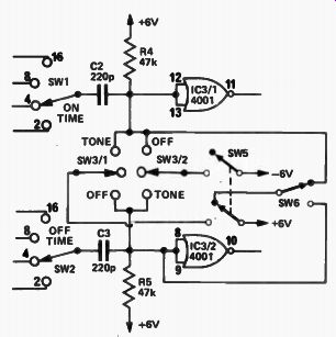
Fig. 1. Partial circuit diagram of the tone-burst generator modified
to perform AB switching.
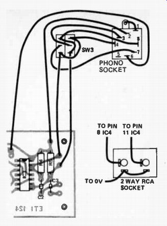
Fig. 2. Interconnection diagram to phono socket and RCA output sockets of AB switch.
To connect the unit for AB testing apply a single input, from the preamplifier (switched to mono), to the normal input socket of the generator. The normal output socket of the generator is not used but the two RCA output sockets are connected back to the left and right channel inputs of the main amplifier.
When SVV6 is operated the mono input will be silently switched between right and left channel speakers.
If using the tape sockets the monitor switch should be in the 'monitor' position and the balance control should be adjusted so that the levels from the two speakers are apparently the same. Make sure that the tone controls are in the flat position, as they can cause phase shifts which prevent the switching occurring at the zero-crossing point.
If the pre and main amplifier terminals are used the preamplifier volume should be adjusted to about half way and separate volume controls used to balance for the difference in efficiencies of the two speakers. If the main amplifier does not have separate volume controls then external ones must be added if balance is to be achieved. In this case the tone controls may be used if required without upsetting the crossover point.
Change over may be effected by using either a toggle switch or a push button. The tone- burst generator controls should be set for eight cycles on and off as this position will effectively remove any contact bounce.
--------------------