(source: Electronics World, Jul. 1963)
With more set makers drawn into the tinted picture, circuit innovation is inevitably under way. Covered here: function, characteristics and adjustment of the latest demodulators.
By WALTER H. BUCHSBAUM Industrial Consultant, ELECTRONICS WORLD
IT has been said often, and it is true, that most of the circuits in today's color TV receivers are not very different from those found in their black-and-white counterparts.
The tuner, i.f., audio, sync, and deflection circuits perform essentially the same functions in both types of sets. Anyone who has come to know what happens inside of a monochrome receiver will have little trouble following the same action in a color design, despite the occasional addition of some refinements. Anyone who has worked on black-and-white defects is well on his way to matching that performance when the same circuits are involved in color.
The great difference involves three special circuit sections. The color tube and its associated driving circuits generate the color display. The color synchronizing and color demodulating sections respond to the special color video information in the composite signal and process it so that it may be used intelligibly.
Of the last two sections, we deal with the demodulating systems here. They are of particular interest now because, with color-set sales under way, there is today more than one design in use. The manufacturer's data is still the best guide to detailed alignment instructions for each of them. A comparison of the various circuits, however, and how they work, provides a better insight into each of them. This understanding is particularly helpful when troubles occur, as fault development grows out of the particular design.

Fig. 1. Despite minor variation from one circuit to another, this general
system for color detection is used in most sets.
Color Demodulator Functions
Color information is recovered from the 3.58-mc subcarrier in the form of two signals, the X and Z signals, which are 62.1° apart in phase. To remove these signals from the 3.58-mc subcarrier, the correct color-synchronizing signal must be available. This sync signal, generated in the color-synchronizing section of the receiver, is locked to the 3.58-mc. sync signal transmitted by the TV station in short bursts with each horizontal-sync pulse.
The X and Z color signals are recovered from their sub-carrier by a process known as synchronous demodulation.
It differs from ordinary AM or FM detection in that the sync signal must be present. The process may be compared to observing fast rotation with a stroboscopic light. If the rate of rotation and the rate at which the strobe light goes on and off are in synchronism, the motion will appear to stand still. If a small speed difference exists, this will appear as slow motion. A practical example of this is the observation of flutter in a phonograph drive mechanism with a strobe light. Without the strobe light, the speed of the phono motor is too great to show the flutter. When the strobe light "stops" the rotation, the flutter becomes visible. In the sane manner does synchronous demodulation permit the color video information to be separated from the higher frequency 3.58-mc. carrier.
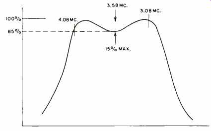
Fig. 2. Normal bandpass amplifier response for Fig. 3 circuit.
The X and Z signals each have a bandwidth of about 1 mc. and contain the elements of the three basic color (or color-difference) signals, Red-Y, Green-Y, and Blue-Y. (The Y or brightness signal is the same as the black-and-white video signal, with a bandwidth of about 4 mc.) When the three color-difference signals are properly combined with the Y signal, the color-picture information is complete.
The addition of the three color-difference signals to the brightness or Y signal is accomplished in the color picture tube by driving each of its three grids with their respective difference signals and simultaneously driving all three cathodes with the Y signal. To obtain the three color-difference signals from the 3.58-mc. color subcarrier, three distinct steps are necessary. Fig. 1 illustrates, in block diagram form, how this is done.
The first step is to amplify the color subcarrier within the bandpass limits required for the X and Z signals. In the bandpass amplifier, the color (or chroma) gain control regulates the amplitude of the color signals before they are separated. Here the color-killer bias is applied to suppress any signals during monochrome transmissions and horizontal-blanking pulses are also applied to suppress all color signals during the retrace period.
The output of the bandpass amplifier is applied to both the X and Z demodulators, in the second step. These stages consist generally of one tube each and operate as synchronous detectors. In each the chroma signal is applied to one tube element and the correct color-sync signal to another tube element. At the input of the demodulators, the signals are still encoded on the 3.58-mc. color subcarrier. At the output, the X and Z signals contain all the color information.
LC filters remove the 3.58-mc. components.

Fig. 3. This widely used circuit for recovering color information is found
in sets made by RCA, G-E, Admiral, and others.
The third step consists of addition, subtraction, and inversion (in the three amplifiers of Fig. 1) to change the X, and Z signals into the three color-difference signals. Note that the green color-difference signal is made up from elements of the red and blue. Addition is performed by simply combining signals across a resistor and subtraction is accomplished in the same manner, except that one signal is inverted or negative. This is also called matrixing.
The three color-difference signals are applied to their respective picture-tube grids, while the Y signal is added at the cathodes. In the block diagram, the three color-drive controls are shown located in the cathode circuit, but in some sets they set the bias at the grid. In either system, these controls determine the gain of the respective color signal or the dynamic color balance, by varying the cathode-grid bias of each electron gun until they are matched.
While the basic functions outlined in Fig. 1 are accomplished in every type of color TV receiver, the actual circuits differ. Those manufacturers who pattern their circuits after the RCA model invariably use separate stages for X and Z demodulators and the color-difference amplifiers. Zenith has its own demodulator system, which combines the functions of demodulating and matrixing in two special stages.
Adjustments and Problems
Although there are a number of adjustments involved in these circuits, the simplified presentation in Fig. 1 shows four basic ones. The color-gain control is on the receiver's front panel, for customer operation. It determines the intensity or saturation of the color in the picture, much as the contrast control establishes the black-and-white level. The three separate gain or drive controls for each of the colors to the CRT are secondary adjustments to be set by the technician. They are adjusted with respect to each other, preferably with a color generator, so that the reproduced levels of red, green, and blue signals are correct and matched to each other. The proper reproduction of white on the screen indicates that these controls are balanced properly.
As for finding defects other than misadjustment, a few simple rules can help localize a problem to a particular stage. If no color appears at all when it is being transmitted, the bandpass amplifier is the first object of suspicion.
It is also possible that both X and Z color-sync information is missing. Sometimes the bandpass amplifier itself may be sound, but it is prevented from operating because color-killer bias is being incorrectly applied to it even during color transmission. This can be determined by a quick check of killer bias with a v.t.v.m. (A defect in the blanking circuit could also cause the continuous application of the bias, although this is relatively rare.)
If only the X demodulator is defective, the red component will appear to be missing, while the blue will come through and the green will appear off in color. Conversely, if the Z demodulator is defective, neither blue nor green will appear, but red will seem normal. A defect in any of the color-difference amplifiers will appear as loss or distortion of the corresponding color, but note that both the blue and the red, or B-Y and R-Y stages, have some effect on green. If the second video-amplifier section is defective, the picture will lack detail and the coloring will be wrong with respect to picture content. Of course, if the first video-amplifier section is dead, no picture at all will appear.
Typical Demodulator Circuits
The most widely used demodulator, in all probability, is the one shown in simplified form in Fig. 3. It appears in all new RCA, G-E, and Admiral sets, as well as others. The bandpass amplifier consists of a single stage, with tuned grid and tuned plate to get maximum gain at the 3.58-mc. color subcarrier. Alignment of both tuned circuits is performed with a sweep generator to produce a response curve like that in Fig. 2.
If a generator that can sweep roughly between 3 and 5 mc. with a center frequency of 3.58 mc. is not available, a higher frequency sweep can be used. Signal swept from about 40 mc. to 50 mc. is injected at the i.f. section, to cover the bandwidth of this part of the receiver. A signal at about 45.75 mc., provided by a single-frequency r.f. generator, is also added. When mixed, these signals produce a heterodyne output at the bandpass amplifier that sweeps the desired range. For specific connections, tuning sequence, and bias arrangements, manufacturer's data should be followed.
Note that, in the circuit of Fig. 3, the color-killer bias is applied at the grid of the bandpass amplifier while the blanking signal goes to the cathode. The output of the bandpass amplifier goes to the control grids of the X and Z demodulators which are 6GY6 tubes, each having a separate suppressor grid. The color-sync signals, in X and Z phase at 3.58-mc., come from the color-sync section and control the gain of each 6GY6 by driving the suppressor grids. At the plate of the X demodulator, inverted R-Y signal appears; at the Z demodulator plate, inverted B-Y is detected.
The LC filter at each demodulator plate keeps the 3.58-mc. component from reaching the color-difference amplifiers, which are essentially simple triode amplifiers with a few additional features. All three cathodes are connected together, which automatically supplies a portion of the red and blue signal to the green amplifier. It also permits cutting off all three stages by the horizontal-blanking amplifier. In addition, the R-Y and B-1' stages contain some plate-to-grid feedback and, in the case of the R-Y tube, some of the plate signal is applied to the grid of the G-Y tube. This produces the subtraction mentioned earlier. The common cathode connection adds red and blue to the cathode of the green stage, but the signal from the plate of the red stage applied to the grid of the green tube is inverted and therefore subtracted in the green stage. The RC network in each difference-amplifier plate circuit is part of a voltage divider to reduce the d.c. applied to the picture-tube grids.
The proper ratio among the three colors is determined by the adjustment of the green and blue drive controls. This is performed on a black-and-white picture to give the proper shade of white because, if the color balance is correct in the absence of color signals, the three electron guns should add to give a good clear white.
A somewhat different version of the demodulator circuit of Fig. 3 is the one shown in Fig. 4. This circuit is used in some RCA models and in the Packard-Bell color sets. A quick comparison shows that here two stages of bandpass amplification are used. The number of tuning adjustments is the same, however, since tuning of the output transformer for the second stage is fixed. Alignment of the bandpass response is the same as previously described. The color-killer bias and the blanking signal are applied respectively to the grid and cathode of the second stage.
The major difference between this and the previously described circuit is in the X and Z demodulator stages. The Packard-Bell circuit uses two moue stages, with the color subcarrier applied to the grids and the color-sync signals applied to the cathodes. This arrangement provides less amplification in the demodulator stage than the pentode circuit of Fig. 3, but the preceding two stages of bandpass amplifiers compensate for it. The matrixing is done again in the three color-difference amplifiers, whose cathodes are connected together in the already described manner. Instead of mixing R-Y plate signal at the green grid, the circuit of Fig. 4 mixes B-Y plate signal with green-plate signal.
All three picture-tube cathodes are tied together and each of the three control grids is biased by a separate potentiometer. In adjusting these controls, the procedure is first to set the green and blue controls to cut-off and then set the red control for a suitable brightness of that color on a monochrome picture. Next, the other two controls are adjusted for correct white balance on monochrome.
The Emerson and DuMont color sets use a demodulator very similar to that shown in Fig. 4. The only differences are in the bandpass amplifier, which is a single pentode stage, and in the color difference amplifier output. The three plate circuits are connected together through a resistance network and returned to a potentiometer that sets the d.c. bias for all three CRT control grids. The cathodes of the color tube are connected as shown in the circuit of Fig. 3.
An entirely different color-demodulator system is used by Zenith. Here the functions of demodulating and matrixing are combined in two special, sheet-beam tubes, as shown in Fig. 5. Two stages of bandpass amplification are used to bring the color subcarrier up to the required amplitude.
Only two tuning adjustments are required, since the tapped coil in the second-stage output is fixed-tuned. The bandpass response required here is shown in Fig. 6. The sharp ledge at the left results from the use of a 4.5-mc. trap before the first bandpass amplifier stage.

Fig. 4. Packard Bell's demodulator circuitry is similar to that in Fig. 3
in principle, somewhat different in execution.
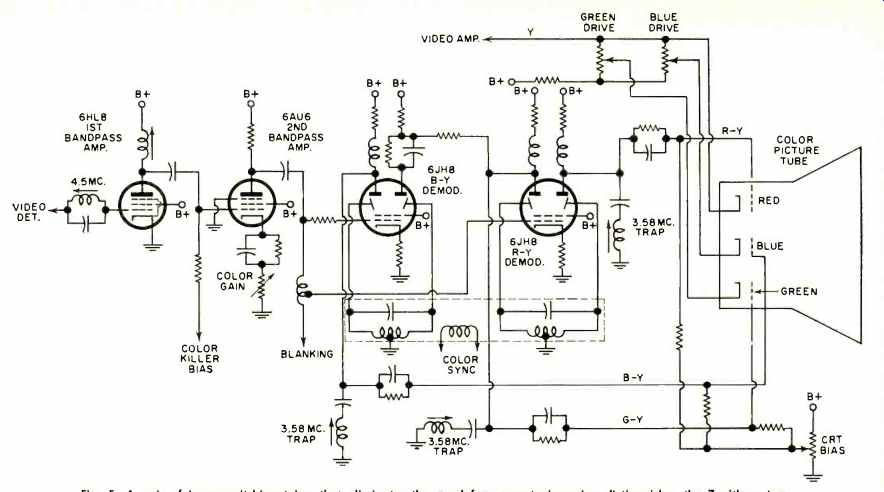
Fig. 5. A pair of beam-switching tubes that eliminates the need for separate
inversion distinguishes the Zenith system.
The demodulator itself produces the R-Y and B-Y difference signals directly without going through the X and Z signal steps. Color-sync signals are applied in push-pull fashion to the two deflection plates of each 6JH8 sheet-beam tube in such a manner that the electron stream from the cathode is switched back and forth between the two plates at the same 3.58-mc. sync frequency. If the color-sync signal is of the correct phase, it will direct the electron beam to the B-Y plate only during the appropriate phase interval. The color subcarrier itself is applied to the grid of the R-Y stage with a small phase difference as compared to B-Y due to the tap on the output coil of the second bandpass amplifier.
This phase difference, together with the phasing of the color-sync signals due to the center-tapped, dual transformer arrangement in the color-sync section, provides the proper demodulating phase relationships. The synchronous switching effect of the sheet-beam tubes takes care of the proper polarity of the detected information, with the signal at one plate of each stage being opposite in polarity with respect to the other. With the need for other inversion circuitry eliminated, only the task of matrixing remains.
One plate of the B-Y demodulator is resistance coupled to one plate of the R-Y stage. These two are combined to form the green color-difference signal, which is applied to the grid of the green gun in the CRT. The complementary or opposite plate of each demodulator, B-Y and R-Y, correspondingly feeds the blue and red CRT grids. Since the 3.58-mc. color subcarrier is still present at each of the demodulator plates, it must be removed. This is accomplished with the three LC networks shown, each one connected between the output to one of the CRT grids and ground. The addition of the black-and-white or Y signal to the three color difference signals is accomplished in the picture tube, with Y information being applied to all three cathodes. The method used is actually similar to that in the circuit of Fig. 3.
Although the circuit used by Zenith is quite different from the roughly similar ones found in other designs, it is too early to assess all advantages or disadvantages between the two systems. As far as tube-use savings go, there are two special, sheet-beam tubes, on the one hand, as compared, on the other, to five fairly conventional triode sections--which are accounted for by two and a half tube envelopes.
There are certainly fewer circuit components in the Zenith design, but alignment of the color-sync output stage seems rather more complex. As to reliability, there has not yet been sufficient service experience, particularly with respect to the newer Zenith system, for dependable evaluation.
Conclusion
Whatever system is used, there are three basic steps required to remove the color information from its subcarrier and present the appropriately detected signals to the color CRT for display. The first step always involves amplification of the 3.58-mc. subcarrier with the appropriate bandwidth, and this is done in the same manner, by and large, in all designs now available.
The second step basically involves the removal of color information from the subcarrier by synchronous detection.
In all systems, with the single exception of the circuit employed by Zenith, this is accomplished by first reconstructing the X and Z signals. Then, in the third and final step, inversion of the signal and matrixing yield the color difference signals for application to the CRT. Although Zenith's distinctive system is like the others in the first step, it combines synchronous demodulation with inversion in the second step, taking advantage of the properties of the dual-plate, sheet-beam tubes. Matrixing finally occurs in the third step as the signal is being applied to the picture tube.
Adjustment and troubleshooting details, as always, are best achieved with reliance on the manufacturer's instructions. However, a basic understanding of the circuits and their functions is important before alignment or fault detection is attempted, even with such aids. Also, based on this understanding, the logical steps that pertain to all circuits, as well as the different ones that apply to circuit variations, become clearer.

Fig. 6. Normal bandpass-amplifier response for Fig. 5 circuit.